It is impossible to determine the cross section of the input cable according to the power of electrical appliances available in the apartment. Tomorrow you will buy, for example, an oil heater with a power of 2.2 kilowatts, or a washing machine, also with a power of 2 kilowatts, or an air conditioner with a power of 1 kilowatt. And what? Change the wiring in the apartment? (may even have an extra outlet). Well, the apartment wiring itself is simple. According to SNiP, there must be one outlet for every two square meters of living space, and a double or triple outlet is also considered one outlet. So you must first select the number of outlets and their location, and if there are powerful electrical receivers in the room, then you need at least two groups of lines for outlets, for general use and for a powerful consumer. There may also be an electric stove in the kitchen, it needs a wire of at least 6 millimeters square for copper and an automatic machine for a rated current of 25 amperes, 32 amperes is already a lot. And for other sockets - a wire of 2.5 mm square for copper and an automatic machine for each line for a rated current of 16 amperes. For lighting, according to the nature of work in the apartment panel, we select an automatic machine for a rated current of 10 amperes and a wire with a cross section of 1.5 millimeters square for copper. At the same time, you need to think about the fact that if too much load is plugged into any outlet, then, according to the current characteristics of the machine, a 16-ampere machine can "hold" a current of 24-25 amperes for 40-50 minutes, although the simultaneous overload of several lines to sockets is unlikely. Well, we decided on the number of lines and machines, their denominations. Now we determine the maximum possible current load on the apartment, given that any machine can be loaded with 100% current and it will not turn off. We summarize the rated currents of all machines and multiply by a utilization factor of 0.7. For example, we got 120 amperes. 120 *0.7=84 amps. Yes, of course, such a load is possible in rare cases, for a short time, and if we used LED lamps for lighting, then a machine with a rated current of 10 amperes will never be loaded with a current of 10 amperes, but the input cable should work reliably in any case. For such a load, only a 60-ampere meter is suitable; for a higher rated current, regional energy meters are allowed to be installed only in exceptional cases. Well, since we use LED lamps for lighting, then such a counter will do. It will withstand a very short overload. Now the introductory machine must be at such a rated current that would allow a short-term overload without shutting down. Considering that a maximum cable or wire with a cross section of 10 square millimeters of copper can be connected to a meter for a rated current of 60 amperes, we select an introductory machine for 40 amperes. It will reliably protect the meter. According to the time-current characteristics of the automaton of group C, it can be seen that it can withstand a current of 60 amperes for 40-50 minutes. Now you need to measure the resistance of the phase-zero loop at the installation site of the apartment shield in order to make sure that the current cutoff of the machine is working. It should be no more than 0.5 Ohm, otherwise you will have to reduce the rated current of the machine and redo the entire apartment shield. We made sure everything is in order. Now we check the cross section of the input cable or wire. The rated current of a two-core copper cable or wire is -55 amperes according to the PUE. It goes through load and overload. We check it by the heating temperature at an ambient temperature of 40 degrees Celsius. In summer, the input line, even without current, can heat up to such a temperature, especially in a closed apartment panel, where both machines and relays emit heat, and the nominal ambient temperature according to the PUE is -25 degrees Celsius. Therefore, we apply a reduction factor for the current load of 0.81. This means that in the summer, in the heat, the input cable will withstand no more than 40 * 0.81 = 44.55 amperes, approximately 45 amperes. This is not enough in terms of current reserve in the event of an overload of 60-70 amperes. The cable can go out of order. In addition, one input cable to the apartment does not meet SNiP for power supply reliability. Therefore, we finally accept - to lay the input with two independent lines according to the "two for one "cable or wire with a cross section of 10 millimeters square over copper. We check. In the worst case, each cable or wire can withstand up to 45 amperes of current, two -85-90 amperes. Even with an overload of 50%, the cables will withstand the load in any heat. We put a terminal block in the floor shield, we lay the section from the meter with a single-core copper wire with a cross section of 10 square millimeters of copper, which can withstand a rated current of 80 amperes according to the PUE, from the terminal block we lay two cables or wires in parallel along the route to the apartment shield, connecting them in parallel on the terminal block and in on the input machine. In case of failure of one cable, we simply bite it out and change it, and the apartment receives power through the remaining cable, which meets the requirements of SNiP for the reliability of power supply. Well, there was a riser in the entrance. If it is made with an aluminum wire of 6 square millimeters, you can temporarily reduce the rating of the introductory machine in the apartment panel to 25 amperes or 32 amperes, or use apartment wiring, taking this into account, otherwise the overload protection in the switchboard house will work. But the bottom line is that your area of responsibility and demarcation of authority begins at the ends of the wire or cable connected to the meter. And everything else is not your competence. So let them change the wiring in their areas in accordance with modern loads and requirements for it.
The comfort and safety in the house depends on the correct choice of the electrical wiring section. When overloaded, the conductor overheats and the insulation may melt, resulting in a fire or short circuit. But it is unprofitable to take a cross section larger than necessary, since the price of the cable increases.
In general, it is calculated depending on the number of consumers, for which the total power used by the apartment is first determined, and then the result is multiplied by 0.75. The PUE uses a table of loads for the cable section. From it, you can easily determine the diameter of the cores, which depends on the material and the passing current. As a rule, copper conductors are used.
The cross section of the cable core must exactly match the calculated one - in the direction of increasing the standard size range. It's most dangerous when it's low. Then the conductor constantly overheats, and the insulation quickly fails. And if you set the appropriate one, it will be triggered frequently.

If you overestimate the cross section of the wire, it will cost more. Although a certain margin is necessary, since in the future, as a rule, you have to connect new equipment. It is advisable to apply a safety factor of about 1.5.
Calculation of total power
The total power consumed by the apartment falls on the main input, which is included in the switchboard, and after it branches into lines:
- lighting;
- socket groups;
- separate powerful electrical appliances.
Therefore, the largest section of the power cable is at the input. On the outlet lines, it decreases, depending on the load. First of all, the total power of all loads is determined. This is not difficult, since it is indicated on the cases of all household appliances and in their passports.

All powers add up. Similarly, calculations are made for each contour. Experts suggest multiplying the amount by 0.75. This is due to the fact that at the same time all devices are not included in the network. Others suggest choosing a larger section. This creates a reserve for the subsequent commissioning of additional electrical appliances that may be purchased in the future. It should be noted that this cable calculation option is more reliable.

How to determine the wire size?
In all calculations, the cable section appears. It is easier to determine its diameter by using the formulas:
- S=π D²/4;
- D= √(4×S/π).
Where π = 3.14.

S = N × D² / 1.27.
Stranded wires are used where flexibility is required. Cheaper solid conductors are used in fixed installations.
How to choose a cable by power?
In order to select the wiring, the table of loads for the cable section is used:
- If the open type line is energized at 220 V, and the total power is 4 kW, a copper conductor with a cross section of 1.5 mm² is taken. This dimension is usually used for lighting wiring.
- With a power of 6 kW, conductors of a larger cross section are required - 2.5 mm². The wire is used for sockets to which household appliances are connected.
- A power of 10 kW requires the use of 6 mm² wiring. Usually it is intended for the kitchen, where an electric stove is connected. The supply to such a load is made on a separate line.
Which cables are best?
Electricians are well aware of the cable of the German brand NUM for office and residential premises. In Russia, brands of cables are produced that are lower in characteristics, although they may have the same name. They can be distinguished by the leakage of the compound in the space between the cores or by its absence.

The wire is produced monolithic and stranded. Each core, as well as the entire twist, is insulated from the outside with PVC, and the filler between them is made non-combustible:
- So, the NUM cable is used indoors, since the insulation on the street is destroyed by sunlight.
- And as an internal cable, the VVG brand is widely used. It is cheap and fairly reliable. It is not recommended for laying in the ground.
- Wire brand VVG is made flat and round. Filler is not used between the cores.
- made with an outer shell that does not support combustion. The cores are made round up to a section of 16 mm², and above - sectoral.
- Cable brands PVS and ShVVP are made multi-wire and are used mainly for connecting household appliances. It is often used as home electrical wiring. It is not recommended to use stranded conductors on the street due to corrosion. In addition, the insulation cracks when bent at low temperatures.
- On the street, armored and moisture-resistant cables AVBShv and VBShv are laid underground. The armor is made of two steel tapes, which increases the reliability of the cable and makes it resistant to mechanical stress.
Determining the current load
A more accurate result is given by the calculation of the cable cross-section in terms of power and current, where the geometric parameters are related to electrical ones.

For home wiring, not only active load, but also reactive load should be taken into account. The current strength is determined by the formula:
I = P/(U∙cosφ).
A reactive load is created by fluorescent lamps and motors of electrical appliances (refrigerator, vacuum cleaner, power tools, etc.).
Current example
Let's find out what to do if it is necessary to determine the cross-section of a copper cable for connecting household appliances with a total power of 25 kW and three-phase machines for 10 kW. Such a connection is made by a five-core cable laid in the ground. The meals at home are from
Taking into account the reactive component, the power of household appliances and equipment will be:
- P life. = 25 / 0.7 = 35.7 kW;
- P rev. \u003d 10 / 0.7 \u003d 14.3 kW.
Input currents are determined:
- I life. \u003d 35.7 × 1000 / 220 \u003d 162 A;
- I rev. \u003d 14.3 × 1000 / 380 \u003d 38 A.
If you distribute single-phase loads evenly over three phases, one will have a current:
I f \u003d 162/3 \u003d 54 A.
I f \u003d 54 + 38 \u003d 92 A.
All appliances will not work at the same time. Taking into account the margin, each phase has a current:
I f \u003d 92 × 0.75 × 1.5 \u003d 103.5 A.
In a five-core cable, only phase cores are taken into account. For a cable laid in the ground, a conductor cross section of 16 mm² can be determined for a current of 103.5 A (table of loads for the cable cross section).
A more accurate calculation of the current strength saves money, since a smaller cross section is required. With a rougher calculation of the cable in terms of power, the cross section of the core will be 25 mm², which will cost more.
Cable voltage drop
Conductors have resistance that must be taken into account. This is especially important for long cable lengths or small cross-sections. PES standards have been established, according to which the voltage drop on the cable should not exceed 5%. The calculation is done as follows.
- The resistance of the conductor is determined: R = 2×(ρ×L)/S.
- The voltage drop is found: U pad. = I×R. In relation to the linear percentage, it will be: U% \u003d (U fall / U line) × 100.
The following notations are accepted in the formulas:
- ρ - resistivity, Ohm×mm²/m;
- S - cross-sectional area, mm².
The coefficient 2 shows that the current flows through two wires.
Example of cable calculation for voltage drop
- The wire resistance is: R \u003d 2 (0.0175 × 20) / 2.5 \u003d 0.28 Ohm.
- The strength of the current in the conductor: I \u003d 7000/220 \u003d 31.8 A.
- Carry voltage drop: U pad. = 31.8×0.28 = 8.9 V.
- Voltage drop percentage: U% \u003d (8.9 / 220) × 100 \u003d 4.1 %.
The carrying is suitable for the welding machine according to the requirements of the rules for the operation of electrical installations, since the percentage of voltage drop on it is within the normal range. However, its value on the supply wire remains large, which can adversely affect the welding process. Here it is necessary to check the lower permissible limit of the supply voltage for the welding machine.
Conclusion
To reliably protect the wiring from overheating when the rated current is exceeded for a long time, the cable cross-sections are calculated according to the long-term permissible currents. The calculation is simplified if the load table for the cable section is used. A more accurate result is obtained if the calculation is based on the maximum current load. And for stable and long-term operation, a circuit breaker is installed in the wiring circuit.
Any replacement or repair of electrical wiring begins with the purchase of an electrical cable! In my practice, I have come across the fact that when buying an electrical cable, people make the wrong choice due to ignorance and being guided by the advice of sellers or electricians, and not an experienced electrician who owns all the modern knowledge and rules for installing and laying electrical wiring.
Many people think that it is not necessary to follow the generally accepted rules and State Standards. This is fundamentally wrong, as my rich practice has shown - compliance with all the rules and regulations in the implementation of electrical repairs and electrical installations - this not only emphasizes the professionalism of the performer, but also the guarantee of reliability, safety and durability of electrical wiring in your house, garage or apartment.
I do not use wires in my work because, firstly, today it is allowed to lay electrical wires only hidden in a wall or floor in HDPE or corrugated pipes - you will need more electrical materials and more time-consuming and labor-intensive work, which means it will cost you more .
Secondly, three separate wires are more expensive than one three-wire cable, which also has a higher resistance to fire and smoke.
Today, only cables with copper conductors are used. because copper has a number of advantages over aluminum!
Aluminum wires should be bought only for old electrical wiring, if you need to replace some of its piece or add, for example, a socket. For these purposes, the AVVGng cable is suitable (Figure 4).
First what you need to pay attention to is. Today, depending on the conditions of laying or use, only electric cables of three brands are used in domestic and domestic conditions:
1. VVGng(picture 1) - for hidden electrical wiring under plaster. This type of cable is resistant to ignition and burning.
2. VVGng-LS- for laying openly on the surface of the ceiling or wall, for example, which will be subsequently sewn up with drywall. Keep in mind that the cable must always be protected from any, including accidental mechanical impact. To protect against mechanical influences, they change, most often PVC boxes. The cable is resistant not only to ignition, but also does not emit smoke.
The analogue of VVGng-LS is a new, more expensive brand NYMng-LS, which is gray in color and is easier to install and cut, because there is a layer of rubber in its design (picture below).

3. And the last option is a white stranded cable of the brand PVA(picture 3), which is used only for extension cords and connecting electrical appliances to a socket. For example, it goes from an electric kettle, etc. to an outlet, to which it is connected through a plug.
Second the main parameter when choosing is the cross section of the cable with copper conductors. At home, depending on the load, a cable with a cross section of 1.5 square millimeters is most often used, which can withstand a load of up to 3.5 and is connected to 16 A or. In rare cases, at higher electrical loads, a 2.5 square mm cable is used, which is connected to a 25 A machine or plug.
Third parameter , this is the number of cores in the cable. For the old 2-wire wiring, a cable with two cores is needed, and for a new three-wire one, with three cores. In addition, to connect a chandelier with two keys, you will need an electric cable with 4 cores.
How is the cable brand VVGng-LS 3x1.5 deciphered?
The first letter A - means that the cable has an aluminum core, and if it is absent - a copper core. In our case, copper.
B - (first in copper cables) means that the core insulation is made of PVC.
B - (second in copper cables) means that the overall insulation of all cores is made of PVC.
G - ("naked") indicates the absence of an additional protective cover.
ng - insulation does not support combustion.
LS - low level of smoke and gas emission when exposed to high temperatures.
3x1.5 - three cores with a cross section of one and a half square millimeters each.
Similar materials.
Before installing additional power wiring or when replacing or repairing wiring in cars and other vehicles, questions arise about the correct selection and use of the wire required for installation.
Vehicle wiring and fire safety, what conditions must be met?
When choosing cables and wires, fire safety requirements are in the first place. In the body of a car, electrical wiring has to be laid along thresholds and corners through random suitable openings and bulkheads. Wires during operation are exposed to low and high temperatures, fuel, oil, acids, water, ice, as well as shaking, vibration, friction, shock and other destructive factors.
It is important to know that in summer the temperature in a car that stands with closed windows in the sun can reach +60 degrees Celsius in the middle latitudes, and +90 degrees in the south. In winter, in severe frost, the temperature of a vehicle in the middle latitudes can reach -40 degrees Celsius, in Siberia and the Urals up to -60 degrees, and in Yakutia up to -70 degrees Celsius.
It is dangerous to use rigid wiring with unreliable insulation that cracks easily. Such a wire can cause a short circuit and a fire. Cables and wires should be used that correspond to the place of their installation in terms of current, as well as in terms of operating and climatic conditions.
It is important that the wire is flexible and has a strong insulation that does not soften when heated and does not tan at sub-zero temperatures. As for the conductive core of the cable, it must be multi-wire and copper, and it must also conduct the rated current well. In conditions of current overload of the circuit and short circuit, before the fuse of the circuit fuse burns out, the current-carrying core (conductor) should not heat up to the melting temperatures of the cable insulation. If a fire has arisen for some reason, the insulation of the wiring should not spread the fire.
Tables of operational characteristics of cables and wires of domestic manufacturers
The domestic cable industry produces a wide range of wires that are suitable for power wiring in vehicles.

Imported cable
Foreign industry produces special cables and wires for the power wiring of cars. These cables are ideally suited to their requirements. They differ in a translucent sheath of brown or red color and a specific weaving of a conductive core, consisting of bundles of wires twisted together.
For inexpensive cables, the wires are made of plain copper, for more expensive ones, they are made of oxygen-free, which gives the wires reduced resistance and, as a result, lower losses.
What is the difference between cable marking of imported and domestic manufacturers?
Imported cables have standard markings, for example:
- power cable is a power cable.
- Proleader, Belsis trade mark of the manufacturer or supplier.
- OFC- wire made of oxygen-free copper.
- #20 - Nr20 - No20 - #20- the size (that is, the caliber) of the conductive core.
- BWG- Birmingham wire gauge.
- AWG- American range.
- SWG- Standard assortment.

Wires of the same caliber in different assortments do not differ significantly in the diameter of the core (wire). The AWG is the basic gauge for vehicle power wiring.
| Gauge, AWG | Analog, mm 2 | Resistance, Ohm/m | Section, mm 2 | Diameter mm |
| 0000 | 95.0 | 0.00018 | 107.2 | 11.68 |
| 000 | 95.0 | 0.00023 | 85.0 | 10.41 |
| 00 | 70.0 | 0.00029 | 67.5 | 9.27 |
| 1/0 | 50.0 | 0.00037 | 53.5 | 8.25 |
| 1 | 35.0 | 0.00047 | 42.4 | 7.35 |
| 2 | 35.0 | 0.00057 | 33.6 | 6.54 |
| 3 | 25.0 | 0.00073 | 26.68 | 5.83 |
| 4 | 25.0 | 0.00091 | 21.15 | 5.19 |
| 5 | 16.0 | 0.0012 | 16.8 | 4.62 |
| 6 | 16.0 | 0.0014 | 13.3 | 4.12 |
| 7 | 10.0 | 0.0018 | 10.55 | 3.67 |
| 8 | 8.0 | 0.0024 | 8.37 | 3.26 |
| 9 | 6.0 | 0.0031 | 6.63 | 2.91 |
| 10 | 5.0 | 0.0036 | 5.26 | 2.59 |
| 11 | 4.0 | 0.0046 | 4.17 | 2.31 |
| 12 | 3.0 | 0.0054 | 3.31 | 2.05 |
| 13 | 2.5 | 0.0074 | 2.62 | 1.83 |
| 14 | 2.0 | 0.0088 | 2.08 | 1.63 |
| 15 | 1.5 | 0.012 | 1.65 | 1.45 |
| 16 | 1.5 | 0.015 | 1.31 | 1.29 |
| 17 | 1.00 | 0.018 | 1.04 | 1.15 |
| 18 | 0.75 | 0.023 | 0.82 | 1.02 |
| 19 | 0.75 | 0.025 | 0.65 | 0.91 |
| 20 | 0.5 | 0.035 | 0.52 | 0.81 |
How to choose a cable section, what you need to know?
To select a cable gauge, you need to know:
- Cable length from load to battery.
- The highest current drawn by the load.
- The rated voltage of the battery or other source that is designed to power the load.
The wire must have such a thickness (cross-section) of the conductor, at which the voltage drop across the cable resistance at long-term (maximum) current consumption is no more than 10 percent of the rated battery voltage. With short-term (impulse) current consumption, a voltage drop of up to 15 percent is allowed.

If the battery has a voltage of +12V, then the maximum allowable voltage drop should be no more than +1.2V (in a pulse +1.8V). On-board network voltage +12V is available for gasoline trucks and cars, light diesel cars and buses. The +24V voltage is used by heavy buses and trucks, as well as diesel off-road vehicles.
The decrease in voltage across the cable resistance is caused by the release of power and heating of the conductor. Since the conductor of the wire is in an insulating sheath, it prevents it from cooling. To reduce heating, it is necessary to choose the conductor cross-section, taking into account the current density coefficient, which for different wire laying conditions can have a value of 1-10 A / mm2.
An example of calculating the cable section for a car
You can find out the maximum current consumed by the load by the fuse rating of the load fuse or by the sum of the ratings of the fuse links when there are several loads. You can also determine the maximum current using the formula Imax \u003d P: 6, if you know the output power of the ULF.

For example, let's calculate the gauge of the wire, if the battery load is +12V - this is a sound power amplifier with an output power of 2x200W. As for the distance between the battery and the amplifier, it is 6 meters.
Calculation:
Load power 2x200W = 400W
The highest current 400W: 6 = 67A
Wire size 67 A: 6 A/mm2 = 11.2 mm2
The wire that is close to 11.2mm2 is #7 AWG 10mm wire.
This wire gauge has a conductor resistance of six meters (see table): 6 m x 0.0018 Ohm = 0.001 Ohm
Voltage drop across the wire conductor: 67 A x 0.0011 ohms = 0.74 V. This is 7.4 percent of + 12V voltage.
From this calculation it follows that the seventh gauge wire is selected correctly.
The cross section of the conductive core is determined by the formula: S = πD 2 /4, where D is the diameter of the core, and π = 3.14.
Requirement for connections and insulation of electrical wiring, connectors and lugs
To prevent a short circuit of the power cable to ground, you need to install a fuse holder on the "positive" wire. It is recommended to install a "flask" type holder. It features a distinctive transparent sealed housing and offers the ability to clamp cable up to gauge #000. It is installed in a wire break near the "positive" terminal of the battery. It is important that the fuse holder housing is securely fastened.

The fuse link rating should be 20-30 percent larger than the maximum current drawn by the load. The cable from the load to the fuse should be one piece (single length) as connections degrade reliability and can cause voltage drops in high power applications. If for some reason you still have to connect the wires, then for their splicing it is necessary to use special "automobile" couplings or distributors with an insulated housing made of heat-resistant plastic and reliable clamping contacts.
If special connecting products are not available, junction boxes, terminal blocks and blocks for domestic and industrial wiring can be used. Do not use PVC insulating tape as an insulator for spliced wire ends. If you need to install a ferrule on a wire for a bolted contact, strip the wire from insulation and put on it a ferrule with an internal diameter of the shank that matches the gauge of the wire. Next, you need to crimp the shank with a special tool, and solder the crimping place with solder.
When laying the cable, it is recommended to place the wire in a corrugated tube of the appropriate diameter in order to avoid damage. If the cable passes through areas with sharp edges, you need to pass the wiring through nylon or rubber seals, that is, wipers.
It is necessary to connect the load and the battery with two different-polarity cables with the same size of the conductive core and insulation of different colors. It is forbidden to use metal chassis or a vehicle body in the form of a "negative" power wire, since due to poor contact connections and welds, a decrease in the load supply voltage is possible.

During the assembly of the car body, the elements of the body and the chassis are interconnected by welding, threaded connections and riveting. These connections provide galvanic contact between the individual parts of the mechanical structure and its rigidity, and for power currents they form body transient total resistances.
Automotive wires, pros and cons
Automotive wires are used in the electrical wiring of various vehicles:
- Combines.
- Tractors.
- Motor scooters and mopeds.
- Buses.
- Cars of various tonnage.
Marks of wires PVGA and PVA are used to connect electrical equipment and devices with different rated voltages. Such devices are mounted on vehicles that are designed for use in cold, temperate and tropical climates. Withstand a high temperature range, which reaches 100 degrees.

Autotractor wires PVA, PVAM and PGVA are single-core wires with high flexibility. The thermal core is made of copper. From above, the cable is covered with PVC insulation - solid or combined colors. The cables are heat-resistant, their service life is at least ten years.
Also wires of this category:
- Do not spread fire.
- Not subject to cracking.
- Resistant to mold fungi.
- Neutral to the influence of motor oils, gasoline and diesel fuel.
- On mounting bends, their properties are preserved.
The article discusses the main criteria for choosing a cable section, gives examples of calculations.
In the markets, you can often see handwritten signs indicating which one the buyer needs to purchase depending on the expected load current. Do not believe these signs, as they mislead you. The cable cross section is selected not only by the operating current, but also by several other parameters.
First of all, it must be taken into account that when using a cable at the limit of its capabilities, the cable cores heat up by several tens of degrees. The current values shown in Figure 1 assume heating of the cable cores up to 65 degrees at an ambient temperature of 25 degrees. If several cables are laid in one pipe or tray, then due to their mutual heating (each cable heats all other cables), the maximum allowable current is reduced by 10 - 30 percent.
Also, the maximum possible current decreases at elevated ambient temperatures. Therefore, in a group network (a network from shields to lamps, sockets and other electrical receivers), as a rule, cables are used at currents not exceeding 0.6 - 0.7 of the values \u200b\u200bgiven in Figure 1.

Rice. 1. Permissible continuous current of cables with copper conductors
Based on this, the widespread use of circuit breakers with a rated current of 25A to protect socket networks laid with cables with copper conductors with a cross section of 2.5 mm2 is dangerous. Tables of reduction factors depending on the temperature and the number of cables in one tray can be found in the Electrical Installation Rules (PUE).
Additional limitations arise when the cable is longer. In this case, the voltage losses in the cable can reach unacceptable values. As a rule, when calculating cables, they proceed from the maximum losses in the line no more than 5%. Losses are not difficult to calculate if you know the resistance value of the cable cores and the estimated load current. But usually, tables of the dependence of losses on the load moment are used to calculate losses. The load moment is calculated as the product of the cable length in meters and the power in kilowatts.
Data for calculating losses at a single-phase voltage of 220 V are shown in table 1. For example, for a cable with copper conductors with a cross section of 2.5 mm2 with a cable length of 30 meters and a load power of 3 kW, the load moment is 30x3 = 90, and the losses will be 3%. If the calculated loss value exceeds 5%, then a larger cable should be selected.
Table 1. Load moment, kW x m, for copper conductors in a two-wire line for a voltage of 220 V for a given conductor cross section

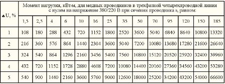
According to table 2, you can determine the losses in a three-phase line. Comparing tables 1 and 2, you can see that in a three-phase line with copper conductors with a cross section of 2.5 mm2, 3% losses correspond to six times the load torque.
A triple increase in the magnitude of the load moment occurs due to the distribution of the load power over three phases, and a double increase due to the fact that in a three-phase network with a symmetrical load (the same currents in the phase conductors), the current in the neutral conductor is zero. With an unbalanced load, the losses in the cable increase, which must be taken into account when choosing the cable section.
Table 2. Load moment, kW x m, for copper conductors in a three-phase four-wire line with zero for a voltage of 380/220 V for a given conductor cross section (click on the figure to enlarge the table)
Cable losses have a significant effect when using low-voltage lamps such as halogen lamps. This is understandable: if 3 Volts drop on the phase and neutral conductors, then at a voltage of 220 V we most likely will not notice this, and at a voltage of 12 V, the voltage on the lamp will drop by half to 6 V. That is why transformers for powering halogen lamps must be maximally approach the lamps. For example, with a cable length of 4.5 meters with a cross section of 2.5 mm2 and a load of 0.1 kW (two 50 W lamps), the load torque is 0.45, which corresponds to a loss of 5% (Table 3).
Table 3. Load torque, kW x m, for copper conductors in a two-wire line for a voltage of 12 V for a given conductor cross section

The tables given do not take into account the increase in the resistance of conductors from heating due to the flow of current through them. Therefore, if the cable is used at currents of 0.5 or more of the maximum allowable current of the cable of a given section, then a correction must be introduced. In the simplest case, if you expect to get losses of no more than 5%, then calculate the cross section based on losses of 4%. Also, losses can increase if there are a large number of cable core connections.
Cables with aluminum conductors have a resistance 1.7 times greater than cables with copper conductors, respectively, and the losses in them are 1.7 times greater.
The second limiting factor for long cable lengths is the excess of the permissible value of the resistance of the phase-zero circuit. To protect cables from overloads and short circuits, as a rule, circuit breakers with a combined release are used. Such switches have thermal and electromagnetic releases.
The electromagnetic release provides instantaneous (tenths and even hundredths of a second) shutdown of the emergency section of the network in case of a short circuit. For example, a circuit breaker, designated C25, has a thermal release of 25 A and an electromagnetic release of 250 A. Circuit breakers of group "C" have a ratio of the breaking current of the electromagnetic release to the thermal release from 5 to 10. But when the maximum value is taken.
The total resistance of the phase-zero circuit includes: the resistance of the step-down transformer of the transformer substation, the resistance of the cable from the substation to the input switchgear (ASU) of the building, the resistance of the cable laid from the ASU to the switchgear (RU) and the resistance of the cable of the group line itself, the cross section of which is required define.
If the line has a large number of cable core connections, for example, a group line from a large number of lamps connected by a loop, then the resistance of the contact connections must also be taken into account. With very accurate calculations, the resistance of the arc at the point of closure is taken into account.
The total resistance of the phase-zero circuit for four-core cables is given in Table 4. The table takes into account the resistance of both the phase and neutral conductors. The resistance values are given at a cable core temperature of 65 degrees. The table is also valid for two-wire lines.
Table 4

In urban transformer substations, as a rule, transformers with a capacity of 630 kV or more are installed. A and more, having an output resistance Rtp less than 0.1 Ohm. In rural areas, 160 - 250 kV transformers can be used. And, having an output impedance of the order of 0.15 Ohm, and even transformers for 40 - 100 kV. A, having an output impedance of 0.65 - 0.25 ohms.
Power supply cables from urban transformer substations to ASUs of houses are usually used with aluminum conductors with a phase conductor cross section of at least 70 - 120 mm2. With a length of these lines of less than 200 meters, the resistance of the phase-zero circuit of the supply cable (Rpc) can be taken equal to 0.3 Ohm. For a more accurate calculation, you need to know the length and cross section of the cable, or measure this resistance. One of the instruments for such measurements (the Vector instrument) is shown in fig. 2.
Rice. 2. Device for measuring the resistance of the phase-zero circuit "Vector"
The resistance of the line must be such that, in the event of a short circuit, the current in the circuit is guaranteed to exceed the operating current of the electromagnetic release. Accordingly, for the C25 circuit breaker, the short-circuit current in the line must exceed 1.15x10x25 = 287 A, here 1.15 is the safety factor. Therefore, the resistance of the phase-zero circuit for the C25 circuit breaker should be no more than 220V / 287A \u003d 0.76 Ohm. Accordingly, for the C16 circuit breaker, the circuit resistance should not exceed 220V / 1.15x160A \u003d 1.19 Ohm and for the C10 machine - no more than 220V / 1.15x100 \u003d 1.91 Ohm.
Thus, for an urban apartment building, assuming Rtp = 0.1 Ohm; Rpk = 0.3 Ohm when using a cable with copper conductors with a cross section of 2.5 mm2, protected by a C16 circuit breaker, in the socket network, the resistance of the cable Rgr (phase and neutral conductors) should not exceed Rgr = 1.19 Ohm - Rtp - Rpc = 1.19 - 0.1 - 0.3 \u003d 0.79 ohms. According to table 4, we find its length - 0.79 / 17.46 \u003d 0.045 km, or 45 meters. For most apartments, this length is enough.
When using the C25 circuit breaker to protect a cable with a cross section of 2.5 mm2, the circuit resistance must be less than 0.76 - 0.4 \u003d 0.36 Ohm, which corresponds to a maximum cable length of 0.36 / 17.46 \u003d 0.02 km, or 20 meters.
When using the C10 circuit breaker to protect a group lighting line made with a cable with copper conductors with a cross section of 1.5 mm2, we obtain the maximum allowable cable resistance 1.91 - 0.4 = 1.51 Ohm, which corresponds to the maximum cable length 1.51 / 29, 1 = 0.052 km, or 52 meters. If such a line is protected by a circuit breaker C16, then the maximum length of the line will be 0.79 / 29.1 \u003d 0.027 km, or 27 meters.


