Today we will assemble a simple design of a breaker based on an electromagnetic relay. This design has a wide range of applications. This relay is mainly used in automotive technology (turn signal interrupter). In fact, this scheme is characterized by maximum ease of assembly; any beginner can repeat it.
The basis of operation is similar to the operation of a low-frequency multivibrator. The circuit consists of an electromagnetic relay and an electrolytic capacitor.
The frequency of operation of the circuit depends on the capacitance of the capacitor. When voltage is applied to the relay, the capacitor is charged, then its capacitance is discharged onto the relay winding, the charging time of the capacitor depends on the capacitor’s capacitance, the larger the capacitance, the more time it takes to charge, therefore, the device will work as a low-frequency chopper.
Using such a simple scheme, you can implement a number of interesting and educational designs. If you connect a light bulb to the corresponding terminals of the relay, the latter will blink periodically, the frequency of these blinks depends on the capacity of the selected capacitor, as mentioned above. In theory, we get a simple turn signal switch - a blinker, which can be used in vehicles, in particular in passenger cars.

The choice of electrolytic capacitor is not critical; you can use capacitors with voltages from 16 to 100 Volts, capacitance from 100 to 4700 μF (depending on what operating frequency is needed).
In my case, I used an electromagnetic relay from a network voltage stabilizer with a current of 10-15 A, but the power of the relay depends on the power of the connected load.

This circuit is distinguished by its particularly precise operation; the time spent in the open state is equal to the time spent in the closed state.
The device can be used to control large loads and not only low-voltage ones. The optimal supply voltage is 12 Volts, although the relay winding is designed for a much higher voltage.
In this article I will explain in detail how to make a multivibrator, which is the first circuit of almost every second radio amateur. As we know, a multivibrator is an electronic device that generates electrical oscillations close to rectangular in shape, which is reflected in its name: “multi-many”, “vibro-oscillation”. In other words, a multivibrator is a relaxation-type rectangular pulse generator with resistive-capacitive positive feedback, using a two-cascade amplifier closed in a positive feedback ring. When the multivibrator operates in self-oscillation mode, periodically repeating rectangular pulses are generated. The frequency of the generated pulses is determined by the parameters of the timing circuit, the properties of the circuit and its power supply mode. The frequency of self-oscillations is also influenced by the connected load. Typically, a multivibrator is used as a pulse generator of relatively long duration, which is then used to generate pulses of the required duration and amplitude.Multivibrator circuit operation
Symmetrical transistor multivibrator
Schematically, the multivibrator consists of two amplifier stages with a common emitter, the output voltage of each of which is applied to the input of the other. When the circuit is connected to the power source Ek, both transistors pass through the collector points - their operating points are in the active region, since a negative bias is applied to the bases through resistors RB1 and RB2. However, this state of the circuit is unstable. Due to the presence of positive feedback in the circuit, the condition?Ku>1 is satisfied and the two-stage amplifier is self-excited. The regeneration process begins - a rapid increase in the current of one transistor and a decrease in the current of the other transistor. Let, as a result of any random change in the voltages at the bases or collectors, the current IK1 of transistor VT1 increase slightly. In this case, the voltage drop across resistor RK1 will increase and the collector of transistor VT1 will receive an increase in positive potential. Since the voltage on capacitor SB1 cannot change instantly, this increment is applied to the base of transistor VT2, turning it off. At the same time, the collector current IK2 decreases, the voltage at the collector of transistor VT2 becomes more negative and, transmitted through capacitor SB2 to the base of transistor VT1, opens it even more, increasing the current IK1. This process proceeds like an avalanche and ends with transistor VT1 entering saturation mode, and transistor VT2 entering cutoff mode. The circuit enters one of its temporarily stable equilibrium states. In this case, the open state of transistor VT1 is ensured by a bias from the power source Ek through resistor RB1, and the closed state of transistor VT2 is ensured by the positive voltage on capacitor SB1 (Ucm = UB2 > 0), which is connected through the open transistor VT1 to the base-emitter gap of transistor VT2.
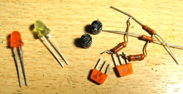
To build a multivibrator The radio components we need are:1. Two KT315 type transistors.
2. Two electrolytic capacitors 16V, 10-200 microfarads (The smaller the capacitance, the more often the blinking).
3. 4 resistors with a nominal value of: 100-500 ohms, 2 pieces (if you set 100 ohms, the circuit will work even from 2.5V), 10 ohms, 2 pieces. All resistors are 0.125 watt.
4. Two dim LEDs (Any color except white).

Lay6 format printed circuit board. Let's start manufacturing. The printed circuit board itself looks like this:
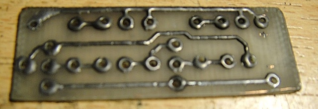
We solder two transistors, do not confuse the collector and base on the transistor - this is a common mistake.
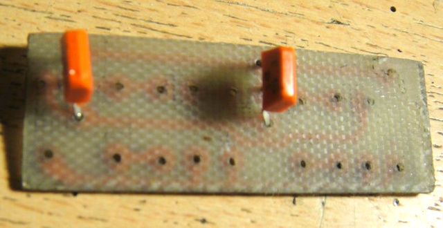
We solder capacitors 10-200 Microfarads. Please note that 10 volt capacitors are highly undesirable for use in this circuit if you will be supplying 12 volt power. Remember that electrolytic capacitors have polarity!

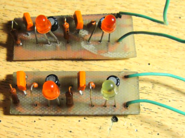
The multivibrator is almost ready. All that remains is to solder the LEDs and input wires. A photo of the finished device looks something like this:
And to make everything clearer to you, here’s a video of a simple multivibrator in action:
In practice, multivibrators are used as pulse generators, frequency dividers, pulse shapers, contactless switches, and so on, in electronic toys, automation devices, computing and measuring equipment, in time relays and master devices. I was with you Boil-:D . (material was prepared upon request Demyan" a)
Discuss the article MULTIVIBRATOR
Multivibrator.
The first circuit is the simplest multivibrator. Despite its simplicity, its scope is very wide. No electronic device is complete without it.
The first figure shows its circuit diagram.
LEDs are used as a load. When the multivibrator is working, the LEDs switch.
For assembly you will need a minimum of parts:
1. Resistors 500 Ohm - 2 pieces
2. Resistors 10 kOhm - 2 pieces
3. Electrolytic capacitor 47 uF for 16 volts - 2 pieces
4. Transistor KT972A - 2 pieces
5. LED - 2 pieces
KT972A transistors are composite transistors, that is, their housing contains two transistors, and it is highly sensitive and can withstand significant current without heat sink.
Once you have purchased all the parts, arm yourself with a soldering iron and start assembling. To conduct experiments, you don’t need to make a printed circuit board; you can assemble everything using a surface-mounted installation. Solder as shown in the pictures.


Let your imagination tell you how to use the assembled device! For example, instead of LEDs, you can install a relay, and use this relay to switch a more powerful load. If you change the values of resistors or capacitors, the switching frequency will change. By changing the frequency you can achieve very interesting effects, from a squeak in the dynamics to a pause for many seconds..
Photo relay.
And this is a diagram of a simple photo relay. This device can be successfully used wherever you want, to automatically illuminate the DVD tray, to turn on the light, or to alarm against intrusion into a dark closet. Two schematic options are provided. In one embodiment, the circuit is activated by light, and in the other by its absence.


It works like this: when light from the LED hits the photodiode, the transistor will open and LED-2 will start to glow. The sensitivity of the device is adjusted using a trimming resistor. As a photodiode, you can use a photodiode from an old ball mouse. LED - any infrared LED. The use of infrared photodiode and LED will avoid interference from visible light. Any LED or a chain of several LEDs is suitable as LED-2. An incandescent lamp can also be used. And if you install an electromagnetic relay instead of an LED, you can control powerful incandescent lamps or some mechanisms.
The figures show both circuits, the pinout (location of the legs) of the transistor and LED, as well as the wiring diagram.

If there is no photodiode, you can take an old MP39 or MP42 transistor and cut off its housing opposite the collector, like this:

Instead of a photodiode, a p-n junction of a transistor will need to be included in the circuit. You will have to determine experimentally which one will work better.
Power amplifier based on TDA1558Q chip.
This amplifier has an output power of 2 X 22 watts and is simple enough for beginner hams to replicate. This circuit will be useful for you for homemade speakers, or for a homemade music center, which can be made from an old MP3 player.

To assemble it you will need only five parts:
1. Microcircuit - TDA1558Q
2. Capacitor 0.22 uF
3. Capacitor 0.33 uF – 2 pieces
4. Electrolytic capacitor 6800 uF at 16 volts
The microcircuit has a fairly high output power and will need a radiator to cool it. You can use a heatsink from the processor.
The entire assembly can be done by surface mounting without the use of a printed circuit board. First, you need to remove pins 4, 9 and 15 from the microcircuit. They are not used. The pins are counted from left to right if you hold it with the pins facing you and the markings facing up. Then carefully straighten the leads. Next, bend pins 5, 13 and 14 up, all these pins are connected to the power positive. The next step is to bend pins 3, 7 and 11 down - this is the power supply minus, or “ground”. After these manipulations, screw the chip to the heat sink using thermal conductive paste. The pictures show the installation from different angles, but I will still explain. Pins 1 and 2 are soldered together - this is the input of the right channel, a 0.33 µF capacitor must be soldered to them. The same must be done with pins 16 and 17. The common wire for the input is the minus power supply or ground.
Simple circuits of homemade LED flashers based on transistor multivibrators. Figure 1 shows a multivibrator circuit that switches two LEDs. The LEDs blink alternately, that is, when HL1 is on, the HL2 LED is not on, but vice versa.
You can mount the diagram into a Christmas tree toy. When the power is turned on, the toy will flash. If the LEDs are of different colors, then the toy will simultaneously blink and change the color of the glow.
The blinking frequency can be changed by selecting the resistances of resistors R2 and R3; by the way, if these resistors are not of the same resistance, you can ensure that one LED glows longer than the other.
But two LEDs are somehow not enough for even the smallest tabletop Christmas tree. Figure 2 shows a circuit that switches two strings of three LEDs. There are more LEDs, and so is the voltage required to power them. Therefore, now the source is not 5-volt, but 9-volt (or 12-volt).
Fig.1. Circuit of the simplest flasher using LEDs and transistors.

Fig.2. Circuit of a simple flasher with six LEDs and two transistors.

Rice. 3. LED flasher circuit with powerful outputs for load.
As a power source, you can use a power supply from an old television game console like “Dandy” or buy an inexpensive “mains adapter” with an output voltage of 9V or 12V in the store.
And yet, even six LEDs are not enough for a home Christmas tree. It would be nice to triple the number of LEDs. Yes, and use not simple LEDs, but extremely bright ones. But, if each garland already has nine LEDs connected in series, and even super bright ones, then the total voltage required for their glow will already be 2.3Vx9=20.7V.
Plus, a few more volts are needed for the multivibrator to function. Moreover, the “network adapters” on sale are usually inexpensive ones, no more than 12V.
You can get out of this situation if you divide the LEDs into three groups of three. And turn on the groups in parallel. But this will lead to an increase in current through the transistors and disrupt the operation of the multivibrator. However, it is possible to make additional amplification stages using two more transistors (Fig. 3).
Two garlands are good, but they just blink alternately. If only there were at least three! For such a case, there is a so-called “three-phase multivibrator” circuit. It is shown in Figure 4.

Fig.4. Multivibrator circuit with three transistors.
If you turn on LED garlands in the collector circuits of transistors (Fig. 5), you will get a kind of running fire effect. The speed of reproduction of the light effect can be adjusted by replacing capacitors C1, C2 and C3 with capacitors of other capacities. And also replacing resistors R2, R4, R6 with resistors of a different resistance. As capacitance or resistance increases, the LED switching speed decreases.

Rice. 5. Multivibrator circuit to obtain the effect of running fire.
And in Figure 6 there is a more powerful version with 27 LEDs. In the “flashing lights” according to the diagrams in Figures 3 and 6, you can use almost any LEDs, but it is still desirable to be super bright or super bright.

Rice. 6. Diagram of a more powerful flasher with 27 LEDs.
Installation can be done on prototype printed circuit boards, which are sold in radio parts stores. Or without boards at all, soldering the parts together.
MULTIVIBRATOR
Multivibrator. I’m sure many people started their amateur radio activities with this scheme.This was also my first diagram - a piece of plywood, holes punched with nails, the leads of the parts were twisted with wire in the absence of a soldering iron.And everything worked great!
LEDs are used as a load. When the multivibrator is working, the LEDs switch.
Assembly requires a minimum of parts. Here is the list:
- - Resistors 500 Ohm - 2 pieces
- - Resistors 10 kOhm - 2 pieces
- - Electrolytic capacitor 1 uF for 16 volts - 2 pieces
- - Transistor KT972A - 2 pieces (KT815 or KT817 will also work), KT315 is also possible, if the current is no more than 25mA.
- - LED - any 2 pieces
- - Power supply from 4.5 to 15 volts.
The figure shows one LED in each channel, but several can be connected in parallel. Or in series (a chain of 5 pieces), but then the power supply is not less than 15 volts.
KT972A transistors are composite transistors, that is, their housing contains two transistors, and it is highly sensitive and can withstand significant current without heat sink.
To conduct experiments, you don’t need to make a printed circuit board; you can assemble everything using a surface-mounted installation. Solder as shown in the pictures.
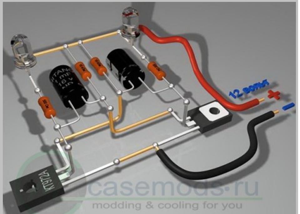
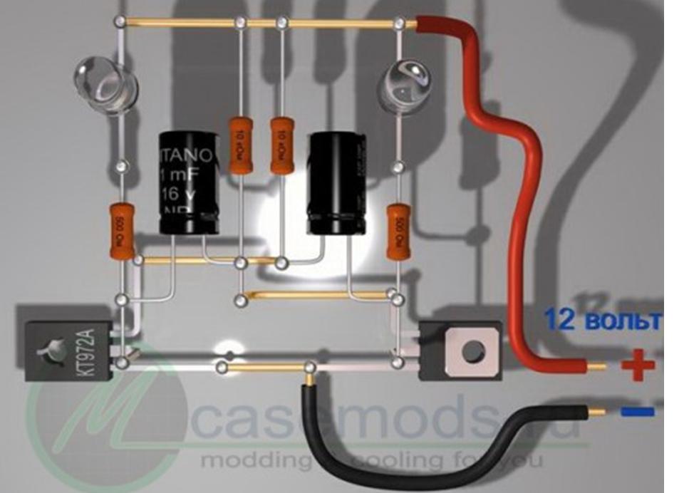
The drawings are specially made from different angles and you can examine in detail all the details of the installation.


