The glow of fluorescent lamps, related to gas-discharge lamps, is UV radiation resulting from the action of an electric discharge on mercury vapor in the bulb.
This radiation is invisible to the human eye; What makes it visible is a layer of phosphor deposited on the inner surface of the bulb.
To create an electrical discharge in a fluorescent lamp, which has a fairly high resistance, a high voltage pulse is correspondingly required, after which a resistance must be included in the power circuit to prevent it from burning out to limit the current.
To accomplish this task, special ballast equipment (ballast) or so-called ballast is used.
Currently, there are two types of ballasts: electronic ballast - electronic ballast and electronic ballast - electromagnetic ballast. Each of them, of course, has its own advantages and disadvantages in use. This article provides a detailed description and diagrams for connecting fluorescent lamps using EMCG.
Connection diagrams for fluorescent lamps
In addition to the fluorescent lamp itself (L), the circuit contains a switch, a choke (Dr) and a starter (St). A choke is a device that provides a high voltage pulse for ignition and limiting its current (power loss - in fact, it is ballast), in order to avoid burnout of the spirals.


The starter is structurally a gas-discharge light bulb with one or two movable contacts, the bulb of which contains an inert gas, most often neon. The operating voltage of the starter is always lower than the mains voltage, but exceeds the voltage of the fluorescent lamp.
Description of the circuit operation. When voltage is applied to the lamp coils through a choke connected in series with it, it is supplied to the contacts of a parallel-connected starter. As a result of the occurrence of a glow discharge between the electrodes, the latter short-circuit due to their bending.
By closing the starter contacts, as can be seen from the diagram, the voltage at the lamp contacts increases, ensuring the heating of its mercury vapor and coils. By analogy, their opening occurs: cooling of the contacts leads to extension.
This opening causes a high voltage surge in the inductor - a pulse sufficient to ignite the lamp. Thus, switching occurs, and the voltage applied to the starter will be insufficient to cause a discharge in it and short circuit the electrodes.
The dotted line highlights the connection of capacitor C. It is an optional element of the circuits and is designed to reduce the level of radio interference caused by the closure of the starter contacts at the moment of switching on.
Fluorescent lamps (FLLs) are widely used to illuminate both large areas of public premises and as household light sources. The popularity of fluorescent lamps is largely due to their economic characteristics. Compared to incandescent lamps, this type of lamp has high efficiency, increased light output and a longer service life. However, a functional disadvantage of fluorescent lamps is the need for a starting starter or a special ballast (ballast). Accordingly, the task of starting the lamp when the starter fails or is absent is urgent and relevant.
The fundamental difference between an LDS and an incandescent lamp is that the conversion of electricity into light occurs due to the flow of current through mercury vapor mixed with an inert gas in a bulb. Current begins to flow after breakdown of the gas by high voltage applied to the electrodes of the lamp.
- Throttle.
- Lamp bulb.
- Luminescent layer.
- Starter contacts.
- Starter electrodes.
- Starter housing.
- Bimetallic plate.
- Lamp filaments.
- Ultraviolet radiation.
- Discharge current.
The resulting ultraviolet radiation lies in the part of the spectrum invisible to the human eye. To convert it into a visible light flux, the walls of the bulb are coated with a special layer, a phosphor. By changing the composition of this layer, you can obtain different light shades.
Before the direct launch of the LDS, the electrodes at its ends are heated by passing a current through them or due to the energy of a glow discharge.
High breakdown voltage is provided by ballasts, which can be assembled according to a well-known traditional circuit or have a more complex design.
Starter operating principle
In Fig. Figure 1 shows a typical connection of an LDS with a starter S and a choke L. K1, K2 – lamp electrodes; C1 is a cosine capacitor, C2 is a filter capacitor. A mandatory element of such circuits is a choke (inductor) and a starter (chopper). The latter is often used as a neon lamp with bimetallic plates. To improve the low power factor due to the presence of inductor inductance, an input capacitor is used (C1 in Fig. 1).

Rice. 1 Functional diagram of LDS connection
The LDS startup phases are as follows:
1) Warming up the lamp electrodes. In this phase, the current flows through the circuit “Network – L – K1 – S – K2 – Network”. In this mode, the starter begins to close/open randomly.
2) At the moment the circuit is broken by the starter S, the magnetic field energy accumulated in the inductor L is applied in the form of high voltage to the electrodes of the lamp. An electrical breakdown of the gas inside the lamp occurs.
3) In breakdown mode, the lamp resistance is lower than the resistance of the starter branch. Therefore, the current flows along the circuit “Network – L – K1 – K2 – Network”. In this phase, inductor L acts as a current-limiting reactor.
Disadvantages of the traditional LDS starting circuit: acoustic noise, flickering with a frequency of 100 Hz, increased start-up time, low efficiency.
Operating principle of electronic ballasts
Electronic ballasts (EPG) use the potential of modern power electronics and are more complex, but also more functional circuits. Such devices allow you to control the three startup phases and adjust the light output. The result is longer lamp life. Also, due to the lamp being powered with a current of a higher frequency (20÷100 kHz), there is no visible flicker. A simplified diagram of one of the popular electronic ballast topologies is shown in Fig. 2.

Rice. 2 Simplified circuit diagram of electronic ballasts
In Fig. 2 D1-D4 – mains voltage rectifier, C – filter capacitor, T1-T4 – transistor bridge inverter with transformer Tr. Optionally, the electronic ballast may contain an input filter, a power factor correction circuit, additional resonant chokes and capacitors.
A complete schematic diagram of one of the typical modern electronic ballasts is shown in Fig. 3.

Rice. 3 Diagram of BIGLUZ electronic ballasts
The circuit (Fig. 3) contains the main elements mentioned above: a bridge diode rectifier, a filter capacitor in the DC link (C4), an inverter in the form of two transistors with wiring (Q1, R5, R1) and (Q2, R2, R3), inductor L1, transformer with three terminals TR1, trigger circuit and lamp resonant circuit. Two windings of the transformer are used to turn on transistors, the third winding is part of the resonant circuit of the LDS.
Methods for starting LDS without specialized ballasts
When a fluorescent lamp fails, there are two possible reasons:
1) . In this case, it is enough to replace the starter. The same operation should be carried out if the lamp flickers. In this case, upon visual inspection, there are no characteristic darkening on the LDS flask.
2) . Perhaps one of the electrode threads has burned out. Upon visual inspection, darkening may be noticeable at the ends of the bulb. Here you can use known starting circuits to continue operating the lamp even with burnt-out electrode threads.
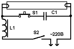
For emergency starting, a fluorescent lamp can be connected without a starter according to the diagram below (Fig. 4). Here the user plays the role of starter. Contact S1 is closed for the entire period of lamp operation. Button S2 is closed for 1-2 seconds to light the lamp. When S2 opens, the voltage on it at the moment of ignition will be significantly higher than the mains voltage! Therefore, extreme caution should be exercised when working with such a scheme.

Rice. 4 Schematic diagram of starting an LDS without a starter
If you need to quickly ignite an LVDS with burnt filaments, then you need to assemble a circuit (Fig. 5).
Rice. 5 Schematic diagram of connecting an LDS with a burnt filament
For a 7-11 W inductor and a 20 W lamp, the C1 rating is 1 µF with a voltage of 630 V. Capacitors with a lower rating should not be used.
Automatic circuits for starting an LDS without a choke involve using an ordinary incandescent lamp as a current limiter. Such circuits, as a rule, are multipliers and supply the LDS with direct current, which causes accelerated wear of one of the electrodes. However, we emphasize that such circuits allow you to run even an LDS with burnt-out electrode threads for some time. A typical connection diagram for a fluorescent lamp without a choke is shown in Fig. 6.

Rice. 6. Block diagram of connecting an LDS without a choke

Rice. 7 Voltage on the LDS connected according to the diagram (Fig. 6) before start-up
As we see in Fig. 7, the voltage on the lamp at the moment of starting reaches the level of 700 V in approximately 25 ms. Instead of an HL1 incandescent lamp, you can use a choke. Capacitors in the diagram of Fig. 6 should be selected within 1÷20 µF with a voltage of at least 1000V. Diodes must be designed for a reverse voltage of 1000V and a current of 0.5 to 10 A, depending on the lamp power. For a 40 W lamp, diodes rated for current 1 will be sufficient.
Another version of the launch scheme is shown in Fig. 8.

Rice. 8 Schematic diagram of a multiplier with two diodes
Parameters of capacitors and diodes in the circuit in Fig. 8 are similar to the diagram in Fig. 6.
One of the options for using a low-voltage power supply is shown in Fig. 9. Based on this circuit (Fig. 9), you can assemble a wireless fluorescent lamp on a battery.

Rice. 9 Schematic diagram of connecting LDS from a low-voltage power source
For the above circuit, it is necessary to wind a transformer with three windings on one core (ring). As a rule, the primary winding is wound first, then the main secondary (indicated as III in the diagram). Cooling must be provided for the transistor.
Conclusion
If the fluorescent lamp starter fails, you can use an emergency “manual” start or simple DC power circuits. When using circuits based on voltage multipliers, it is possible to start a lamp without a choke using an incandescent lamp. When operating on direct current, there is no flicker or noise from the LDS, but the service life is reduced.
If one or two filaments of the cathodes of a fluorescent lamp burn out, it can continue to be used for some time, using the above-mentioned circuits with increased voltage.
Lamps based on tubular fluorescent lamps are still in demand in office and industrial premises, garages and workshops, and remain as a legacy in Soviet-era buildings. Despite the obvious disadvantages, such as large dimensions, humming during startup and operation, unstable glow and flickering depending on voltage fluctuations, some connection complexity, it will not be economically feasible to replace oblong fluorescent lamps with compact ones if the electronic filling of the lamps is in order, and only replacement of fluorescent lamps is required.
The fact is that the operating principle of gas-discharge light sources, as well as their energy consumption, does not depend on size and shape, and the cost of a tubular lamp without purchasing electronic components will be much less than installing a standard socket and purchasing a compact lamp that includes the necessary electronics.
 lamp contacts
 Therefore, it is worth thinking about how to check a fluorescent lamp and related devices before switching to other types of lamps.
Operating principle and connection diagrams
First you need to understand the operating principle of a fluorescent electric lighting device. A glow discharge in an atmosphere of inert gases with admixtures of mercury vapor causes a glow in the ultraviolet spectrum, which is converted into visible light using a phosphor applied to the inner wall of the flask.
 types of fluorescent lamps
 To start a discharge (electrical breakdown, after which the gas is ionized and becomes a conductor of electric current), a high voltage pulse is needed between the cathodes of low-pressure gas-discharge lamps, the connection and replacement of which are discussed in this article.
 general diagram of a fluorescent lamp
 To start and operate these luminaires, two switching schemes are widely used, using:
- Electromagnetic ballast (electromagnetic ballast) and starter;
- Electronic ballast (electronic ballast - electronic ballast).
Scheme with electronic ballasts
The algorithm for starting a fluorescent lamp is the same for both options, but the circuit with an electronic ballast (choke)
Diagram with throttle and starter
and the starter is more clear. When voltage is applied, the cathodes heat up, after which a high voltage surge occurs (about 1 kV) and an electrical breakdown occurs in the gas and current begins to flow in it.
The starter has a sealed glass bulb with bimetallic contacts,
 starter
 between which, when voltage is applied, a glow discharge begins to occur, heating the normally open contact plates.
The heated contacts close, and current flows through the filaments of the lamp cathodes, heating them.
After a few seconds, the bimetallic contacts of the starter cool and open, causing a sharp induction surge due to the inductance of the inductor - at this moment the lamp begins to glow.
 LDS 20 W
 Capacitors are used to compensate reactive power and smooth out electromagnetic interference.
Circuit with electronic ballasts
A high frequency current is generated in the electronic ballast, and the algorithm for starting and operating the lamp is programmed in the electronic circuit.
 disassembled ballast
 Thanks to electronic ballasts, it is also possible to carry out cold instantaneous start-up of fluorescent lamps, which reduces the service life of gas-discharge lamps, but can extend their service in the event of burnout or degeneration of the cathodes, as evidenced by blackening at the ends of the tube.
 electronic ballast
 The possibility of a cold start and the method of its implementation must be indicated in the device passport. A diagram with electronic ballasts is always available on the device body, following it exactly, you can on one's own connect a fluorescent lamp.
 Connection diagram
 Since electronic ballasts are more economical and create less noise and electromagnetic interference, they are gradually replacing outdated chokes.
Replacing a burnt out lamp
If the problem is only how to replace a fluorescent lamp, without connecting electronic components, then you must first disassemble the lamp and, being careful, rotate the tube along its axis. The direction of rotation can be viewed on the holders, or determined experimentally.
 lamp replacement
 Having turned the glass tube 90º, it is lowered down so that the contacts pass through the slots in the holders.
 Lamp contact holder
 The new lamp is oriented so that the contacts are in a vertical plane and fit into the slot, after which the tube is turned in the opposite direction. After turning on the power, make sure that the lamp starts up normally, and then insert the diffuser lamp into place.

The burnt-out lamp is disposed of, or they try to “reanimate” it using a cold start method.
How to check a fluorescent lamp and components
When connecting a fluorescent lamp, you need to be sure that the lamp and ballasts are working properly. To do this, you need to check the cathode filaments with a tester - their resistance should be within 10 Ohms.

If the tester shows infinite resistance,

then you should not throw away the lamp - it can be used for some time in cold start mode. The starter contacts are normally open, and its capacitor does not conduct direct current, that is, when testing, the resistance should be as high as possible - tens and hundreds of megohms.
When the ohmmeter probes touch the inductor terminals, the resistance should smoothly decrease to a constant value characteristic of the winding, within a few tens of ohms.
Unfortunately, using a conventional ohmmeter it is impossible to detect an interturn short circuit in the inductor winding, but if the multimeter has an inductance measurement and the parameters of the ballast are known, then if the values do not match, this defect can be identified.
A faulty throttle is also indicated by the burnout of the newly installed new lamp. Since the electronic ballast contains a complex circuit with many elements,
 electronic block diagram
 then there is no way to test it with a multimeter.
Fluorescent lamps from the very first releases and are partially still lit using electromagnetic ballasts - EMP. The classic version of the lamp is made in the form of a sealed glass tube with pins at the ends.
What do fluorescent lamps look like?
Inside it is filled with an inert gas with mercury vapor. It is installed in cartridges through which voltage is supplied to the electrodes. An electric discharge is created between them, causing an ultraviolet glow, which acts on the phosphor layer applied to the inner surface of the glass tube. The result is a bright glow. The switching circuit for fluorescent lamps (LL) is provided by two main elements: electromagnetic ballast L1 and glow discharge lamp SF1.

LL connection diagram with electromagnetic choke and starter
Ignition circuits with electronic ballasts
A device with a throttle and starter works according to the following principle:
- Supplying voltage to the electrodes. The current does not pass through the gaseous medium of the lamp at first due to its high resistance. It enters through the starter (St) (Fig. below), in which a glow discharge is formed. In this case, a current passes through the spirals of the electrodes (2) and begins to heat them up.
- The starter contacts heat up, and one of them closes, since it is made of bimetal. The current passes through them and the discharge stops.
- The starter contacts stop heating up, and after cooling, the bimetallic contact opens again. A voltage pulse occurs in the inductor (D) due to self-induction, which is sufficient to ignite the LL.
- A current passes through the gaseous medium of the lamp; after starting the lamp, it decreases along with the voltage drop across the inductor. The starter remains disconnected, since this current is not enough to start it.

Fluorescent lamp connection diagram
Capacitors (C 1) and (C 2) in the circuit are designed to reduce the level of interference. A capacitance (C 1) connected in parallel to the lamp helps reduce the amplitude of the voltage pulse and increase its duration. As a result, the service life of the starter and LL increases. The capacitor (C 2) at the input provides a significant reduction in the reactive component of the load (cos φ increases from 0.6 to 0.9).
If you know how to connect a fluorescent lamp with burnt-out filaments, it can be used in an electronic ballast circuit after a slight modification of the circuit itself. To do this, the spirals are short-circuited and a capacitor is connected in series to the starter. According to this scheme, the light source will be able to work for some more time.
A widely used switching method is with one choke and two fluorescent lamps.

Switching on two fluorescent lamps with a common choke
2 lamps are connected in series between each other and the choke. Each of them requires the installation of a parallel connected starter. To do this, use one output pin at the ends of the lamp.
For LLs, it is necessary to use special switches so that their contacts do not stick due to high inrush current.
Ignition without electromagnetic ballast
To extend the life of burnt-out fluorescent lamps, you can install one of the switching circuits without a choke and starter. For this purpose, voltage multipliers are used.

Diagram for switching on fluorescent lamps without a choke
The filaments are short-circuited and voltage is applied to the circuit. After straightening, it increases 2 times, and this is enough for the lamp to light up. Capacitors (C 1), (C 2) are selected for a voltage of 600 V, and (C 3), (C 4) - for a voltage of 1000 V.
The method is also suitable for working LLs, but they should not operate with DC power. After some time, mercury accumulates around one of the electrodes, and the brightness of the glow decreases. To restore it, you need to turn the lamp over, thereby changing the polarity.
Connection without starter
Using a starter increases the heating time of the lamp. However, its service life is short. Electrodes can be heated without it if secondary transformer windings are installed for this purpose.

Connection diagram for a fluorescent lamp without a starter
Where the starter is not used, the lamp has a quick start designation - RS. If you install such a lamp with a starter, its coils can quickly burn out, since they have a longer warm-up time.
Electronic ballast
Electronic ballast control circuitry has replaced older daylight sources to eliminate their inherent shortcomings. Electromagnetic ballast consumes excess energy, often makes noise, breaks down and damages the lamp. In addition, the lamps flicker due to the low frequency of the supply voltage.
Electronic ballasts are an electronic unit that takes up little space. Fluorescent lamps are easy and quick to start, without creating noise and providing uniform illumination. The circuit provides several ways to protect the lamp, which increases its service life and makes its operation safer.
The electronic ballast works as follows:
- Warming up the LL electrodes. Start-up is quick and smooth, which increases lamp life.
- Ignition is the generation of a high voltage pulse that pierces the gas in the flask.
- Combustion is the maintenance of a small voltage on the lamp electrodes, which is sufficient for a stable process.

Electronic throttle circuit
First, the alternating voltage is rectified using a diode bridge and smoothed by a capacitor (C 2). Next, a half-bridge high-frequency voltage generator using two transistors is installed. The load is a toroidal transformer with windings (W1), (W2), (W3), two of them are connected in antiphase. They alternately open the transistor switches. The third winding (W3) supplies resonant voltage to the LL.
A capacitor (C 4) is connected in parallel to the lamp. Resonant voltage is supplied to the electrodes and penetrates the gaseous environment. By this time the filaments have already warmed up. Once ignited, the lamp's resistance drops sharply, causing the voltage to drop sufficiently to maintain combustion. The startup process lasts less than 1 second.
Electronic circuits have the following advantages:
- start with any specified time delay;
- installation of a starter and a massive throttle is not required;
- the lamp does not blink or hum;
- high-quality light output;
- compactness of the device.
The use of electronic ballasts makes it possible to install it in the base of a lamp, which is also reduced to the size of an incandescent lamp. This gave rise to new energy-saving lamps that can be screwed into a regular standard socket.
During operation, fluorescent lamps age and require an increase in operating voltage. In the electronic ballast circuit, the ignition voltage of the glow discharge at the starter decreases. In this case, its electrodes may open, which will trigger the starter and turn off the LL. Then it starts again. Such blinking of the lamp leads to its failure along with the inductor. In an electronic ballast circuit, a similar phenomenon does not occur, since the electronic ballast automatically adjusts to changes in the parameters of the lamp, selecting a favorable mode for it.
Lamp repair. Video
Tips for repairing a fluorescent lamp can be obtained from this video.
LL devices and their connection circuits are constantly being developed in the direction of improving technical characteristics. It is important to be able to choose suitable models and use them correctly.
Reading time ≈ 3 minutes
The most common lighting source used in office, industrial and public buildings are fluorescent lamps. Recently, due to saving energy resources, they have also begun to be frequently used in home life.
Standard lamps, in addition to their advantages, such as low energy consumption, ease of installation, low cost, also have a number of design disadvantages. Some of them come from advantages: by using cheap, outdated circuits and materials, the manufacturer reduces the cost of the lamp, while at the same time worsening consumer qualities in advance.
Connection diagram for fluorescent lamps

Connecting one or two factory-made fluorescent lamps can be studied by disassembling a regular lamp. The usual standard, widely used wiring diagram for fluorescent lamps includes a starter, inductor, connecting wires, capacitor, and the lamps themselves. In this case, the so-called electromagnetic control system is used.
It is quite possible to improve the level of illumination on your own and remove annoying buzzing and blinking. To do this, it is necessary to replace the outdated control system with a modern electronic one (electronic ballasts).

First, you need to dismantle the lamp and remove all the filling from it. By purchasing a new electronic unit, based on the parameters of your lamp, it will be possible to connect fluorescent lamps without a choke and starter. For this work, you will need screwdrivers with different blades, wire cutters for stripping wires, a screwdriver for attaching control units, electrical tape, and a tester screwdriver.
Connecting electronic ballasts for fluorescent lamps is easy to do with minimal knowledge of electrical circuits and skills in working with electrical wiring. In fact, the lamp itself will contain the block itself, a set of wires and fluorescent lamps.

Before starting work, you need to select a sufficient space in the luminaire body to install the electronic control unit, guided by the convenience of connection to the terminals located on its body. We fasten the block to the body using self-tapping screws with a regular screwdriver. We connect the control equipment with the lamp and the connection terminal.
The connection diagram for 2 fluorescent lamps is similar, they are simply connected in series, and, based on this, the power of the electronic unit should be twice the power of the lamps. The same principle applies when connecting three or more lamps in one housing.

After assembling the entire structure, you need to make sure that all conductors are connected correctly, after which you can install the lamp in place. Having checked with a tester that there is no voltage in the network, we connect the lamp to the electrical wiring, connecting the wires through a special terminal block.
The last step is to turn on the voltage to verify the correct operation of the lamp. If the circuit, for example, connecting two fluorescent lamps, was done correctly, then the process itself will be strikingly different from the original one. Firstly, the lamps will light up instantly, without so-called warming up; secondly, the low-frequency hum will disappear, the light will stop pulsating, noticeable to the human eye, and the overall luminosity will increase.


