In short, my native charger for a Nokia phone with an otem, bitch, a millipad connector gave me a fuck:
It always goes away, falls out. Shit is shorter.
Fortunately, the phone has a microUSB connector, which has already become a standard. Well, mine, at least, has. Yes, and do not kick for Nokia, I have a phone for communication. For entertainment a tablet. (like fucked). So through this connector, the phone charges perfectly if there is a charge.

And then the other day they brought another, outdated, "original" Chinese charger for Nokia. They are demolished to me from time to time by employees. I don’t know the fuck, I don’t fix them to anyone, well, except for this case, and then for myself. Looks like because of the soldering iron on the table and a special reputation in our office. Well, not the point. She was with exactly that correct microUSB connector:

I'll say right away the simplest thing would be to re-solder the lace to the native charger, but I was not looking for simple ways. For the experience gained, though small, is very useful. By the way, you can still buy a new charger, but it costs, travel time. I forget, then laziness.
I share my impressions, experiences, well, a little humor will not hurt.
I gave myself some coffee, so that I was flipping through Google for typical situations with charging, experienced advice, repair cases, so I could not fall asleep. It gave little sense, for there are thousands of them, if not billions, like the Chinese. Although he gave a general idea of \u200b\u200bthe charging circuitry and an understanding of the dicky, or completely fucked up.

I covered the table with a rough draft, took out a few suitable corpses, plugged the soldering iron into the socket, and turned it around for troubleshooting:

Charging with the right lanyard went around the world solidly. Almost all semiconductor content has burned out:

The second of the bins, xs from which, without a lace, looked perky, but did not work:

For everyone, I also had a working power supply, xs from which, but with a fairly competent circuitry, just change the swollen condender:

But I felt sorry for him and put aside. If it is impossible to fix that thread from the first two, I would take it.
On the way of low resistance, the troubleshooting of the second charge showed a burnt out diode and a resistor, which the cunning Chinese, due to the reduction in cost, use as fuses. I drink:

View from the other side. By the way, the circuitry is of a normal level, an order of magnitude better than the first charge:

It was decided to use the first one as a donor, the diode is normal, and the resistor is already burned out:

I found an analogue in the bins, which I paid a little later:

ATTENTION! AHTUNG! WORNING!


I soldered the diode and resistor, poked it into the socket, and the LED lit up cheerfully turned green:

There is a contact.
"The resistor is weak," said the charge, and the sad blue smoke confirmed her words.
Okay, I said, and climbed into the bins in search of an analogue. Along the way, finding a varistor and a choke, which narrow-eyed saved on. I re-solder:

New test, everything is ok (the photo did not work out very well).
Of course, reality, and what is most interesting, the principles of this method were tested by Nikola Tesla long before the appearance of a mobile phone.
The physics of such a wireless charging circuit is as follows. The role of the charger is performed by the transmitting circuit, the charging for the phone itself consists of two circuits - a transmitter and a receiver. A flat coil located in the phone itself is used as a receiving circuit, and the transmitter is made in the form of a stand, inside which the transmitting coil is located.

Electrical vibrations are transferred from one circuit to another by means of electromagnetic induction, and then rectified and fed to the battery.
The transmitter, as you can see, is a common blocking generator based on one field-effect transistor. We make the coil by winding 40 turns of copper wire, with a branch in the middle on a rim with a diameter of 100 mm.
You can use field-effect transistors IRFZ44 / 48, IRL3705, and many others, even bipolar ones.
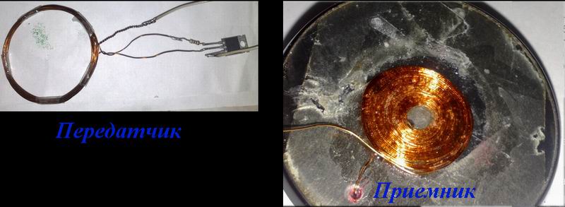
The receivers will have to tinker a little longer, the coil consists of 25 turns of 0.3-0.4mm wire wound one after another, reinforcing the turns with superglue, the work is quite painstaking, but you can handle it.

Such a wireless charger for a mobile phone can charge it in 7-8 hours, it can be faster, but then the size of the coil increases and there is no way to place it in the phone case.
Circuitry, the charger is a DC-DC converter that allows you to charge your mobile phone or tablet from a 12 volt network. The basis of the circuit is the 34063api chip, designed specifically for this.

The 34063api has a built-in output stage that can deliver up to three amperes to the load, which allows you to charge tablets and smartphones. The output voltage is exactly 5 volts. The inductor consists of 20 turns of 0.6mm wire. Input and output capacitors can be excluded from the circuit; they only filter noise.
Somehow it happened that my charger from Nokia burned out, on the street - 45 and running to buy a new one is not an option, so I decided to use my work laptop as a charge.
We only need two connectors - we already have one, and the other I took from the USB cable for the printer.
We strip the wires, and from the USB side we use only the red and black wires and connect them red to red, black to black. And then we insulate the junction, it is best to use a suitable diameter thermocambric, but I did not have it.
I think that many fans of active tourism have faced the problem that there is simply nowhere to charge a mobile phone or smartphone, sometimes an additional battery does not even solve the problem. The traveler's radio amateur always has a way out, you can assemble a homemade structure for charging from standard AA batteries.

The scheme of the device is sufficient, simple and will come out much cheaper than a ready-made device.
As a rule, repairing such an inexpensive device is economically unprofitable.
Especially in non-poor countries. Average price $ 5.
But it happens that there is no extra money, but there is time and spare parts.
No shop nearby. Circumstances do not allow. Then it's not about the price.
In my case, everything was simple - one of my two chargers broke Nokia AC-3E, friends brought a bag of broken chargers. Among them were a dozen branded Nokia chargers. It was a sin not to take it.
The search for a circuit did not lead to anything, so I took a similar one and remade it for AC-3E. A lot of chargers for mobile phones are made according to a similar scheme. As a rule, the difference is not significant. Sometimes the denominations are changed, a little more or a little less elements, sometimes a charge indication is added. And basically the same thing.
Therefore, this description and diagram are useful for repairing not only AC-3E.
The repair instructions are simple and written for non-specialists.
The scheme is clickable and of good quality. 
THEORY.
The device is a blocking generator operating in a self-oscillating mode. It is powered by a half-wave rectifier (D1, C1) with a voltage of approximately +300 V. Resistor R1, R2 limits the starting current of the device and acts as a fuse. The blocking generator is based on a transistor MJE13005 and a pulse transformer. A necessary element of the blocking generator is a positive feedback circuit formed by winding 2 of the transformer, elements R5, R4 C2.
The 5v6 zener diode limits the voltage at the base of the MJE13005 transistor to within five volts.
Damping chain D3, C4, R6 limit voltage surges on the winding 1 of the transformer. At the moment when the transistor is turned off, these surges can exceed the supply voltage by several times, therefore, the minimum allowable voltage of the capacitor C4 and diode D3 must be at least 1 kV.
PRACTICE.
1. Disassembly. The self-tapping screws holding the charger cover in this device look like a triangular asterisk. As a rule, there is no special screwdriver at hand, so you have to get out as best you can. I unscrewed it with a screwdriver, which during operation itself sharpened under all sorts of crosses.


Sometimes the chargers are assembled without bolts. In this case, the body halves are glued together. This indicates the low cost and quality of the device. Disassembling such a memory is a little more difficult. It is necessary to crack the body with a mild screwdriver, gently pressing on the joint of the halves.
2. External examination of the board. More than 50% of defects can be detected precisely by external examination. Burnt resistors, a darkened board will show you the location of the defect. A bursting case, cracks on the board will indicate that the device has been dropped. Chargers are operated in extreme conditions, so falling from everywhere is a frequent cause of failure.
Five out of a dozen memory devices that I happened to do were trite pins bent through which 220 volts are fed to the board.

To fix it, just bend the contacts slightly towards the board.
To check whether the contacts are to blame or not, you can solder the power cord to the board, and measure the voltage at the output - the red and black wires.


3.
Broken cord at the charger outlet. It breaks as a rule at the plug itself or at the base of the charger. Especially for those who like to talk while charging the phone.
It is called by the device. Insert the pin of a thin part into the center of the connector and measure the resistance of the wires.
4.
Transistor + resistors. If there is no visible damage, first of all, you need to evaporate the transistor and ring it. It should be borne in mind that the transistor
MJE13005 the base is on the right, but it also happens vice versa. The transistor can be of a different type, in a different case. Let's say MJE13001 looks like a Soviet kt209 with a base on the left.

Instead, I put MJE13003. You can put a transistor from any burned out lamp - housekeeper. In them, as a rule, the filament of the bulb itself burns out, and the two high-voltage transistors remain intact.
5. Consequences of overvoltage. In the simplest case, they are expressed in a short-circuited diode D1 and a broken resistor R1. In more difficult cases, the MJE13005 transistor burns out and inflates the capacitor C1. All of this is simply changed to the same or similar details.
In the last two cases, it will be necessary, in addition to replacing burned-out conductors, to check the resistors around the transistor. With the diagram, this will not be difficult to do.
I wonder what the Siemens charger (power supply) consists of and whether it is possible to repair it yourself in case of a breakdown.
First, the block needs to be disassembled. Judging by the seams on the case, this unit is not intended for disassembly, therefore, the thing is disposable and there is no need to pin great hopes in case of breakdown.

I had to literally raskurochit case of the charger, it consists of two tightly glued parts.

Inside is a primitive board and a few details. Interestingly, the board is not soldered to the 220V plug, but is attached to it with a pair of pins. In rare cases, these contacts can oxidize and lose contact, and you think that the block has broken. But the thickness of the wires going to the mobile phone connector pleased me pleasantly, you don't often find a normal wire in disposable devices, usually it's so thin that it's scary to even touch it).
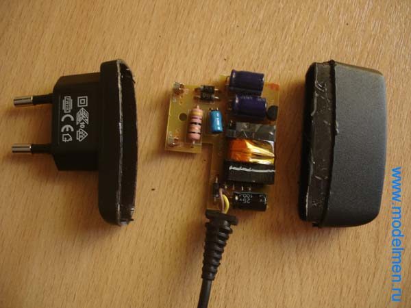
There were several details on the back of the board, the circuit turned out to be not so simple, but still it is not so complicated that you would not be able to fix it yourself.

Below in the photo are the contacts of the inside of the case.
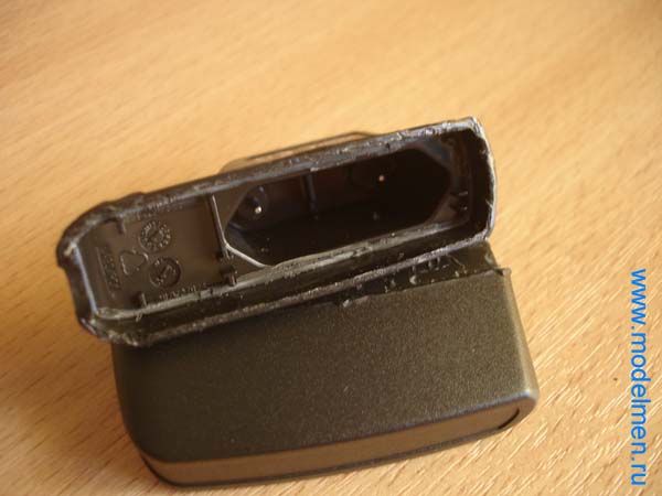
There is no step-down transformer in the charger circuit; an ordinary resistor plays its role. Then, as usual, a couple of rectifying diodes, a pair of capacitors for rectifying the current, then a choke and finally a zener diode with a capacitor complete the chain and output the reduced voltage to a wire with a connector to a mobile phone.

The connector has only two pins.

I present another device from the series "Don't Take!"
The kit comes with a simple microUSB cable, which I will test separately with a bunch of other laces.
I ordered this charger for the sake of curiosity, knowing that in such a compact case it is extremely difficult to make a reliable and safe 5V 1A mains supply device. The reality turned out to be harsh ...
Comes in a standard bubble wrap bag.
The case is glossy, wrapped in a protective film.
Dimensions with fork 65x34x14mm 


Charging immediately turned out to be inoperative - a good start ...
I had to disassemble and repair the device at the beginning in order to be able to test it.
It is very simple to understand - on the latches of the plug itself.
The defect was discovered immediately - one of the wires to the plug fell off, the soldering turned out to be of poor quality. 
The second soldering is not better 
The board itself is installed normally (for the Chinese), the soldering is good, the board is washed. 


Real device diagram 
What problems were found:
- Quite weak attachment of the plug to the body. The possibility of her remaining torn off in the outlet is not excluded.
- Lack of input fuse. Apparently the same wires to the plug are protection.
- Half-wave input rectifier - unjustified savings on diodes.
- Small capacity of the input capacitor (2.2μF / 400V). For the operation of a half-wave rectifier, the capacity is clearly insufficient, which will lead to increased voltage ripple on it at a frequency of 50 Hz and to a decrease in its service life.
- Lack of filters for input and output. Small loss for such a small and low-powered device.
- The simplest converter circuit based on one weak MJE13001 transistor.
- A simple 1nF / 1kV ceramic capacitor in an interference suppression circuit (shown separately in the photo). This is a gross violation of the security of the device. The capacitor must be of at least Y2 class.
- There is no damper circuit for damping backstop emissions of the primary winding of the transformer. This impulse often breaks through the power key element when it heats up.
- Lack of protection against overheating, overload, short circuit, overvoltage.
- The overall power of the transformer clearly does not pull at 5W, and its very miniature size casts doubt on the presence of normal insulation between the windings.
Now testing.
Because the device is not initially safe, the connection was made through an additional mains fuse. If something happens, at least it will not burn and leave without light.
I checked it without a case so that the temperature of the elements could be controlled.
No-load output voltage 5.25V
Power consumption without load less than 0.1W
Under a load of 0.3A or less, the charging works quite adequately, the voltage keeps normally at 5.25V, the ripple at the output is insignificant, the key transistor heats up within normal limits.
Under a load of 0.4A, the voltage begins to walk a little in the range of 5.18V - 5.29V, the ripple at the output is 50Hz 75mV, the key transistor heats up within normal limits.
Under a load of 0.45A, the voltage begins to noticeably walk in the range of 5.08V - 5.29V, the ripple at the output 50Hz is 85mV, the key transistor starts to overheat slowly (burns the finger), the transformer is warm.
Under a load of 0.50A, the voltage begins to walk strongly in the range of 4.65V - 5.25V, the ripple at the output is 50Hz 200mV, the key transistor is overheated, the transformer is also quite hot.
Under a load of 0.55A, the voltage wildly jumps in the range of 4.20V - 5.20V, the ripple at the output is 50Hz 420mV, the key transistor is overheated, the transformer is also quite hot.
With an even greater increase in the load, the voltage drops sharply to indecent values.
It turns out that this charging can actually produce a maximum of 0.45A instead of the declared 1A.
Further, the charger was assembled into a case (along with a fuse) and left in operation for a couple of hours.
Oddly enough, the charging did not fail. But this does not mean at all that it is reliable - having such a circuitry, it cannot last long ...
In the short-circuit mode, the charge quietly died 20 seconds after switching on - the key transistor Q1, the resistor R2 and the optocoupler U1 broke. Even the additionally installed fuse did not have time to burn out.
For comparison, I will show you how the simplest Chinese 5V 2A charging from a tablet looks like inside, made in compliance with the minimum permissible safety standards. 

Taking this opportunity, I would like to inform you that the lamp driver from the previous review has been successfully finalized, the article has been supplemented.


