The mechanism for raising and lowering the KamAZ platform provides:
Raising and lowering the platform;
Stopping it in any intermediate position during lifting or lowering;
Automatic limitation of the maximum angle of rise;
Automatic limitation of pressure in the hydraulic system.
The control of the mechanism for raising and lowering the KamAZ platform is electropneumatic remote control, with switches installed on the instrument panel in the driver's cab.
Technical characteristics of the KAMAZ lifting mechanism
Dump truck model: Kamaz-55111 / Kamaz-55102
Power take-off - From gearbox through power take-off
Transmitted power (average), W (hp) - 8826 (12) / 8826 (12)
Efficiency - 0.7 / 0.7
Hydraulic oil pressure. kPa (kgf):
Nominal 13,730 (140) / 13730 (140)
Maximum limited by safety valve 19613 (200) / 19613 (200)
Working stroke time (lifting of a loaded platform) at engine crankshaft rotation speed of 2200 rpm, - 18/16
Idling time (lowering the platform after unloading), s - 18/16
Fuel consumption for 100 working cycles, l - 5.5 / -
Gear ratio, power take-off. 0.59 / 0.59
The total gear ratio from the engine crankshaft to the driven shaft of the hydraulic pump. ... 1.26 / 1.26
Pump type - NSh 32-L-2
Pump flow at a pump shaft speed of 1900 ... 2000 rpm, l / min - 56/56
Number of stages (hydraulic cylinder extendable links) - 3/5
Diameter of hydraulic cylinder extension links, mm:
First - 95, second - 75, third - 56
Working stroke of the hydraulic cylinder extension, mm:
First - 1100, second - 1140, third - 1160, total - 3400
Maximum effort [oil pressure in the hydraulic system 13730 kPa (140 kgf / cm2)] when extending the links, kN (tf):
1st - 97.1 (9.9) / 217 (22.14)
Second - 60.8 (6.2) / 147.8 (15.6)
Third - 33.8 (3.45) / 97.1 (9.9)
4th - - / 60.8 (6.2)
5th - - / 33.8 (3.45)
The KamAZ hydraulic lifting mechanism consists of a power take-off, an oil pump, a hydraulic cylinder, a control valve, a platform lifting valve, electro-pneumatic valves, an oil tank with a filter and a system of pneumatic and hydraulic drives.
In addition to these unified units, the platform lifting mechanism of the Kamaz-55102 dump truck has a locking device designed to connect the tractor hydraulic system to the trailer hydraulic system, and a hydraulic valve directing the oil flow to the tractor hydraulic cylinder or to the trailer hydraulic cylinder. The valve is attached to the control valve.
Fig. 1. Power take-off KAMAZ
1 - cork; 2 and 21 - gaskets; 3 - the axis of the intermediate gear: 4 and 16 - washers; 5 and 23 - bearings; 6 - intermediate gear; 7 - a thrust ring; 8 - lock washer; 9- nut; 10 and 12 - rings; 11 - compensator; 13 - set screw, 14 - power take-off case; 15 - spring; 17 - pneumatic cylinder body; 18 - a sealing ring; 19 - piston; 20 - pump NSh32-L-2; 22 - half-coupling; 24 - gear
Power take-off KamAZ with an oil pump (Fig. 1) is designed to take power from the gearbox and is attached to the crankcase on the right side.
Between the flanges of the crankcase of the power take-off box and the KamAZ gearbox, sealing gaskets are installed, with the help of which the gearing of the gear wheels is regulated. If it is necessary to replace the gaskets, their total thickness “must be maintained.
The KamAZ power take-off can be turned on only when the air pressure in the car's pneumatic system is at least 490 kPa (5 kgf / cm8) and with the clutch disengaged.
The oil pump is a gear type. To ensure normal operation of the pump and increase its service life, it is necessary to carefully filter the oil poured into the tank.
Figure: 2. Hydraulic cylinder of the platform lifting mechanism KamAZ-55111
1 - support for the hydraulic cylinder; 2 - insert; 3 - nut; 4 - ball head; 5 - lock washer; 6 and 10 - thrust rings; 7 - wiper clips; 8 - cleaners: 9 - washers; 11- protective rings; 12 - cuffs: 13 - spacers; 14 - plungers; 15 and 19 - split rings; 16 - hydraulic cylinder body; 17 - branch pipe; 18 - half rings, 20 - half ring of the clip; 21 - clamp: 22 - the bottom of the hydraulic cylinder; 23 - bolt
The hydraulic cylinder (Fig. 2 and 3) of the KamAZ lifting mechanism is telescopic, single-acting. In the housing of the KamAZ hydraulic cylinder there are retractable links, the course of which is limited by retaining rings.
The direction of the sliding links is provided at the bottom by guides, and at the top by brass bushings held by retaining rings.
To increase the durability of the KamAZ hydraulic cylinder, the outer surfaces of the sliding links are knurled, chrome-plated and polished.
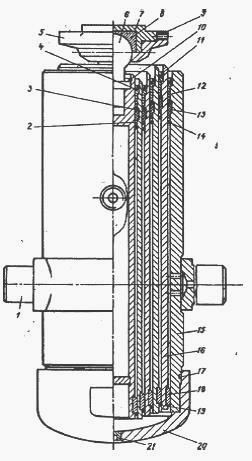
Fig. 3. Hydraulic cylinder of the platform lifting mechanism KamAZ-55102
1 - pin; 2 - spacer; 3 - protective ring; 4 - wiper; 5- support of the hydraulic cylinder; 6 - ball head; 7 - insert; 8 - insert; 9 - locking screw; 19-ring for fastening the ball head; 11 - retaining ring of the guide sleeve; 12-guide sleeve; 13 - cuff; 14 - locking upper ring, 15 - hydraulic cylinder housing, 16 - retractable links; 17 - sealing ring; 18 - semi-ring guide; 19 - locking lower ring: 20 - the bottom of the hydraulic cylinder; 21 drain plug
The retractable links are sealed with rubber cuffs located between the spacers with protective rings. The cavity of the hydraulic cylinder is protected from the ingress of dust and dirt from the outside with wipers.
In the upper part of the KamAZ hydraulic cylinder, a ball head is fixed in the last plunger, the spherical part of which forms a movable connection with the hydraulic cylinder support.
A powder insert allows this connection to function without periodic relubrication. On the Kamaz-55111 car there is one more ball head fixed in the bottom of the hydraulic cylinder.
A branch pipe with a threaded end is welded to the body of the hydraulic cylinder (see Fig. 2) of Kamaz-55111, and a fitting and a pin for fixing it to the frame are welded to the body of the hydraulic cylinder (see Figure 3) of the Kamaz-55102 car. The threaded holes of the branch pipe and the union are intended for connecting the high pressure oil line.
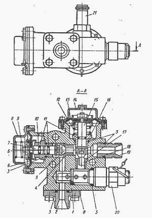
Fig. 4. Control crane KamAZ
1 - case; 2, 10, 16, 19 and 21 - fittings: 3 - o-rings fixed connections: 4. 17 - valve seats: 5 and 18 - valves; 6 and 13 - membranes: 7 and 15 - pusher 8 and 14 - pneumatic chamber covers; 9 and 12 springs; 11 - sealing rings of connections; 20 - safety valve; B - drain hole, B - collar
The KamAZ control valve (Fig. 4) serves to control the flow of the working fluid in the hydraulic system of the tipping mechanism. The platform lift limiting valve connects the pressure and drain lines when the platform reaches its maximum lift angle.
The KamAZ electro-pneumatic valves provide air supply from the vehicle pneumatic system to the pneumatic chambers installed on the power take-off box, control valve and trailer distributor.
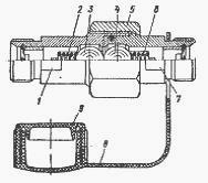
Fig. 5. Locking device KamAZ
1 - housing of the tractor locking device; 2 and 6 - springs; 3 and 4 - balls, 6 - nut; 7 - housing of the trailer locking device, 8 - trailer plug, 9 - tractor plug
The KamAZ locking device (Fig. 5), designed to connect the hydraulic system of a tractor-vehicle with the hydraulic system of the trailer, consists of two bodies 1 and 7, one of which is connected to the discharge line, and the other to the discharge line of the trailer.
During operation of a KamAZ tractor with a trailer, both parts are connected to each other by a nut 5. Balls 3 and 4 of the stop valves are squeezed out of the support belts. When working without a trailer, it must be disconnected from the mains.
To do this, unscrew the nut, the balls, under the action of the springs, will block the holes in the housings, which will prevent oil from leaking out of the hydraulic system.
The oil tank is stamped and consists of two halves. In the upper half there is a filler neck and a filter mounting flange, and in the lower half there is an oil drain hole, closed with a screw plug, and a suction pipe.
A filter mesh is installed in the filler neck. The throat is closed by a threaded cap with an oil level indicator and an opening that communicates the tank cavity with the atmosphere.
To prevent dust and dirt from entering through the hole in the filler cap, a hair seal is provided. An oil tank filter is attached to the flange on the drain line.
The principle of operation of the mechanism for raising and lowering the Kamaz platform

Fig. 6. Scheme of the platform lifting mechanism Kamaz-55111
1, 4 and 19 - electro-pneumatic valves; 2 - control valve; 3, 17 and 20 - pneumatic chambers; 5 - current source with voltage 24 V; 6 - fuse. 7 - power take-off switch; 8 - platform lifting and lowering switch, 9 - control lamp for power take-off switching, 10-hydraulic cylinder; 11 - valve for limiting platform lifting; 12 - filter safety valve; 13 - filter, 14 - oil tank; 15 - oil pump; 16 - power take-off; 18 - hydraulic system safety valve; 1 - lowering the platform; 11 - platform lifting
The sequence of operations when lifting and lowering the Kamaz-55111 platform is as follows (Fig. 6).
To engage the power take-off, disengage the Clutch and put the switch 7 in the “On” position (the indicator lamp 9 will light up).
The current through the thermo-bimetallic fuse 6 is supplied to the solenoid winding of the electro-pneumatic valve 19, the core of which, moving, opens the valve.
Air from the KamAZ receiver enters the cavity of the pneumatic chamber 17 of the power take-off. When the clutch is engaged, the oil pump 15 starts to work.
Oil from the tank 14 through the suction and discharge cavity of the pump flows through the pipeline to the control valve 2, and then is drained into the tank. This circulation of oil helps to warm it up in winter, which improves the working conditions of the hydraulic system of the lifting mechanism.
To raise the KamAZ platform, turn the switch 8 to position 11. In this case, the current passes through the windings of the electro-pneumatic valves 1 and 4, the cores of which, moving, open the valves.
Air from the receiver is supplied to pneumatic chambers 20 and 3 of control valve 2. Oil from the control valve is supplied through pipelines to hydraulic cylinder 10.
Under the action of oil pressure, the links of the hydraulic cylinder are sequentially extended, raising the KamAZ platform. As the platform rises, the hydraulic cylinder tilts; when the maximum lift angle is reached, the hydraulic cylinder body presses the adjusting screw of the platform lift limiting valve 11, and the oil is drained through the valve into the tank.
Raising the platform stops.To stop the KamAZ platform in an intermediate position in the process of lifting or lowering, move the switch 8 to the neutral position. In this case, the electro-pneumatic valves 1 to 4 are turned off, the air leaves the working cavities of the pneumatic chambers 20 and 3 into the atmosphere.
The line of the hydraulic cylinder is closed, and the discharge cavity of the control valve is connected to the drain line, and the oil from the pump is drained through the control valve into the tank.
To lower the KamAZ platform, move the switch 8 to position I. The current flows to the winding of the electro-pneumatic valve 1, the core of which, moving, opens the valve.
Air from the receiver enters the pneumatic chamber 20 of the control valve. Through the control valve, the oil is drained from the hydraulic cylinder into the tank.
At the end of the lowering of the KamAZ platform, it is necessary to set switch 7 to the OFF position (after disengaging the clutch).
In this case, the oil pump stops working. It should be noted that lowering the platform is possible both when the pump is running and when the oil pump is already off, ie, switch 7 is set to the “Off” position.
The principle of operation of the mechanism for raising and lowering the platform Kamaz-55102 is similar to the principle of operation of the mechanism for raising and lowering the platform Kamaz-55111.
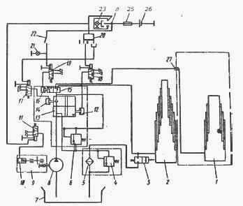
Fig. 7. Scheme of the platform lifting mechanism Kamaz-55102
1-trailer hydraulic cylinder, 2-tractor hydraulic cylinder, 3-limiting valve, 4-filter safety valve, 5-filter, 6-hydraulic safety valve, 7-oil tank, 8-pump, 9 - power take-off, 10, 12, 14 - pneumatic chambers, 11, 17, 18 and 19-electro-pneumatic valves, 13 - control valve, 15 - hydraulic valve, 20- platform lifting mechanism switch, 21- control lamp, 22-hydraulic distributor switch, 23-control lamp for turning on the power take-off, 24-power take-off switch, 25-fuse, 26-current source with voltage 24 V, 27-locking device, I - platform lowering, II - platform lifting
To raise the platform of the KamAZ trailer (Fig. 7), after turning on the power take-off, turn on switch 22 (when lifting the platform of the tractor, it must be turned off); the indicator lamp 21 will light up.
The current flows to the winding of the electromagnet, the core of which, while moving, opens the electric pneumatic valve 19, the air from the receiver enters the pneumatic chamber 16 of the hydraulic distributor, the hydraulic cylinder line of the tractor is closed, and the oil passage opens into the hydraulic cylinder 1 (see Fig. 7) of the trailer.
Further operations for raising and lowering the platform of the Kamaz trailer are similar to the operations for raising and lowering the platform of the tractor.
At the end of the work of the mechanism for lifting the platform of the trailer, it is necessary to turn off the switch 22, while the control lamp 21 will go out. Only alternate operation of the hydraulic cylinders of the tractor and the trailer is possible.
Checking the condition and correctness of regulation of the valve 4 for limiting the lifting of the KamAZ platform: the valve must be securely fixed to the subframe cross member bracket; the adjusting screw 2 must be locked with the lock nut 3.
Avoid kinking the valve stem, oil leaking from the stem seal and threaded pipe connections.
With a correctly adjusted lifting angle of the KamAZ platform, the platform locking pins should freely enter the holes in the subframe brackets. Do not operate the vehicle with impaired platform lift angle adjustment.
To adjust the platform lift angle of the KamAZ-55111 dump truck, do the following:
Unscrew the adjusting screw locknut;
Screw the adjusting screw into the stem until it stops;
Raise the platform to a position where the platform lock pins freely enter the holes in the subframe brackets and lock the platform in this position with the lock pins;
Unscrew the adjusting screw from the valve stem as far as it will go into the cylinder body and secure with the lock nut.
Unlock the platform, lower and raise it again. Make sure that lifting stops when the axis of the locking pins aligns with the axis of the holes in the subframe brackets.
The arrow of the safety cable deflection should be 35 ... 50 mm. If the deflection is different, adjust the cable length by loosening the cable clamps.

Fig. 8. The mechanism of limiting the lifting of the platform Kamaz-55102
1 and 4 - adjusting bolts; 2 and 5 - lock nuts; 3 - lever; 6 - spring; 7 - axis; 8 - restricting valve; 9 - hydraulic cylinder
To adjust the angle of elevation of the Kamaz-55102 platform, do the following:
Lift the platform to the left at an angle of 48 ... 50 ° and place a technological stop under it;
Unscrew the locknut 5 (Fig. 8) of the adjusting bolt 4 and turn out or screw in the bolt so that the nut;
In the same way, use the adjusting bolt to adjust the amount of tipping of the platform to the right, raise the platform again and make sure that its lifting is limited to an angle equal to 48 ... 500.
Pay attention to the position of the lever 3 when the platform is lowered. It should be pressed by the spring 6 against the adjusting screw of the valve 8. Otherwise, adjust the spring tension.
Tipper equipment
The dumping equipment consists of a platform, a subframe, a mechanism for raising and lowering the platform
The platform of the car - a dump truck - is all-metal, welded with a protective visor, an opening tailgate and automatic tailgate locks, it is heated by exhaust gases to prevent the cargo from freezing.
Platform volume 8.5 m3 for 65111, tipping angle -52 °.
Overframe –Welded construction of two spars, cross members and cross-shaped overframe reinforcement.
The platform lifting and lowering mechanism contains:
Power take-off with oil pump, designed to take power from the gearbox .;
Oil pump - gear type of high pressure. Pump flow 55.6 l / min at a speed of 1920 rpm;
Single-acting telescopic hydraulic cylinder;
The control unit used to control the flow of working fluid in the hydraulic system of the tipping mechanism consists of a control valve and an electro-pneumatic valve;
The platform lift limit valve limits platform lift when the platform reaches its maximum lift angle;
Oil tank - stamped in two halves, equipped with filters on the filler neck and drain line.
Pneumatic and hydraulic lines.
PRINCIPLE OF OPERATION
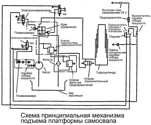
The sequence of operations when raising and lowering the platform of a dump truck (see fig. Schematic diagram of the mechanism for lifting the platform of a dump truck):
To engage the power take-off, disengage the clutch and place the switch in the ON position (the warning lamp will come on). The current through the thermo-bimetallic fuse goes to the solenoid winding of the pneumatic valve No. 3, the core of which, moving, opens the valve. Air from the receiver enters the cavity of the power take-off pneumatic chamber. When the clutch is engaged, the oil pump will start to work. Oil from the tank through the suction and discharge cavities of the pump flows through the pipeline to the control valve, and then is drained into the tank. Such circulation of oil contributes to its warming up in winter, which improves the operating conditions of the hydraulic system of the tipping mechanism;
Move the switch to position II to raise the platform. In this case, the current passes through the windings of electro-pneumatic valves No. 1 and No. 2, the cores of which, moving, open the valves. Air from the receiver is supplied to the pneumatic chambers of the control valve. Oil from the control valve flows through pipelines to the hydraulic cylinder. Under the action of oil pressure, the links of the hydraulic cylinder are sequentially extended, raising the platform.
As the platform rises, the hydraulic cylinder tilts; when the maximum lift angle is reached, the hydraulic cylinder body presses the adjusting screw of the platform lift limit valve, and the oil is drained through the valve into the tank. The lifting of the platform stops;
To stop the platform in an intermediate position while lifting or lowering, move the switch to neutral. In this case, electropneumatic valves No. 1 and No. 2 are turned off, air leaves the working cavities of the pneumatic chambers into the atmosphere. The line of the hydraulic cylinder is closed, and the cavity of the control valve is in communication with the drain line, and the oil from the pump is drained through the control valve into the tank;
To lower the platform, move the switch to position I. The current flows to the winding of the electro-pneumatic valve No. 1, the core of which, moving, opens the valve. Air from the receiver enters the pneumatic chamber and the control valve. Through the control valve, the oil is drained from the hydraulic cylinder into the tank.
After the platform has been lowered, the switch must be set to the OFF position (after disengaging the clutch). In this case, the oil pump stops working.
REGULATION
 Check the condition and correct adjustment of the platform lift limitation valve (see fig. Adjustment of the dump truck platform lift mechanism). The valve must be securely attached to the subframe cross member. The adjusting screw must be locked with a lock nut. Avoid kinking the valve stem, oil leaking from the stem seal and threaded pipe connections. When the platform lifting angle is correctly adjusted, the locking pins (Fig. Installing the safety cables) of the platform should freely enter the holes in the subframe brackets. Do not operate the vehicle with impaired platform lift angle adjustment.
To adjust the lifting angle of the dump truck platform:
Unscrew the lock nut (see Fig. Adjustment of the mechanism for lifting the platform of the dump truck) of the adjusting screw;
Screw the adjusting screw into the stem until it stops;
Raise the platform to a position where the platform lock pins freely enter the holes in the subframe brackets and lock the platform in this position with the lock pins;
Unscrew the adjusting screw from the valve stem as far as it will go into the cylinder body and secure with the lock nut.
Unlock the platform, lower and raise it again.
Make sure that lifting stops when the axis of the locking pins 3 (see Fig. Installation of safety cables) coincides with the axis of the holes in the subframe brackets. The deflection arrow of the safety cable should be 35 ... 50 mm. If the deflection is different, adjust the cable length by loosening the cable clamps.
CHECKING THE OIL LEVEL AND CHECKING THE HYDRAULIC SYSTEM
Check the oil level in the tank with the platform lowered with a pointer mounted in the tank cap. The level should be located between marks H and B on the indicator.
 To refuel the hydraulic system:
Unscrew the cap of the filler neck of the oil tank, remove, rinse and replace the strainer;
Fill with oil up to the B mark on the oil level indicator;
Raise and lower the platform 3 ... 4 times at an average speed of the engine crankshaft (1100 ... 1300 rpm) to pump the system and remove air from it;
Check the oil level, top up if necessary to mark B.
Page 1 of 2
Check the condition and operation of the platform lift limitation valve.
Secure the lift control valve to the subframe cross member bracket. The valve stem must not be bent. The adjusting screw must be securely locked with a lock nut.
To adjust the lifting angle of the platform of the KamAZ-55111 dump truck, do the following:
Unscrew the locknut of the lift limiting valve adjusting screw;
Screw the adjusting screw into the stem until it stops; raise the platform to a position where the locking pins freely enter the holes in the subframe brackets, and lock the platform in this position with locking pins;
Unscrew the adjusting screw from the valve stem as far as it will go into the cylinder body and secure with a lock nut.
Unlock platform, lower and raise it again. Make sure platform lifting stops when the axis of the locking pins aligns with the axis of the holes in the subframe brackets.
To adjust the lifting angle of the platform of a dump truck mod. 55102, you need to perform the following operations:
Raise the platform to the left at an angle of 48-50 ° and place a technological stop under it;
Unscrew the adjusting bolt locknut and unscrew or screw in the bolt so that the lift angle is equal to the specified one, then tighten the locknut; in the same way adjust the amount of platform lift to the right;
Lower and raise the platform: make sure that lifting is limited to an angle of 48-50 °.
Pay attention to the position of the lever when the platform is lowered. It should be spring-pressed against the restriction valve adjusting screw. Otherwise, adjust the spring tension.
|
Air leaks (check by ear) and oil are not allowed. |
The deflection should be 35-50 mm. Adjust the deflection by loosening the cable clamps. The cable should not have strands break. |
|
The tightening torque of the nuts is 79-98 Nm (8-10 kgf m). |
The tightening torques of the nuts 1 of the subframe mounting bolts M12 - 79-98 Nm (8-10 kgf m), the nuts 2 of the subframe tightening bolts M16 - 176-216 Nm (18-22 kgf m), the M14 bolts - 137-157 N m (14 -16 kgf m). |
|
The tightening torque of the bolts is 39-49 Nm (4-5 kgf-m). |
The tightening torque of the nuts of 1 clamps is 54-62 Nm (5.5-63 kgf-m). The tightening torque for the nuts of the 2 bolts is 137-147 Nm (14-15 kgf-m). |
|
The tightening torque of the bolt nuts is 44-53 Nm (45-54 kgf-m). Drain the sediment from the hydraulic cylinder of the platform lifting mechanism (for KamAZ-55102). |
The oil level in the tank is checked with the platform lowered by a pointer mounted in the tank cap. The level should be between marks H and B on the indicator. To refuel the hydraulic system: Unscrew the cap of the filler neck of the oil tank, remove, rinse and replace the strainer; Fill with oil up to the B mark on the oil level indicator; Raise and lower the platform 3-4 times at an average engine speed (1100-1300 rpm) to remove air from the system; Check oil level, top up if necessary to mark B. |
 Figure: 2. Check the condition and operation of the platform lift control valve.
 Figure: 3. Check the deflection of the platform lift safety cable.
 Figure: 4. Secure the front subframe brackets.
 Figure: 5. Tighten the subframe pinch bolts.
 Figure: 6. Secure power take-off and oil pump.
 Figure: 7. Fasten the shock absorber.
 Figure: 8. Install the platform shock absorbers.
 Changing the oil in the hydraulic system of the platform lifting mechanism.
The mechanism for raising and lowering the KamAZ platform provides:
Raising and lowering the platform;
Stopping it in any intermediate position during lifting or lowering;
Automatic limitation of the maximum angle of rise;
Automatic limitation of pressure in the hydraulic system.
The control of the mechanism for raising and lowering the KamAZ platform is electropneumatic remote control, with switches installed on the instrument panel in the driver's cab.
Technical characteristics and parameters of the KAMAZ lifting and lowering mechanism
Dump truck model: Kamaz-55111 / Kamaz-55102
Power take-off - From gearbox through power take-off
Transmitted power (average), W (hp) - 8826 (12) / 8826 (12)
Efficiency - 0.7 / 0.7
Hydraulic oil pressure. kPa (kgf):
Nominal 13,730 (140) / 13730 (140)
Maximum limited by safety valve 19613 (200) / 19613 (200)
Working stroke time (lifting of a loaded platform) at an engine speed of 2200 rpm, - 18/16
Idling time (lowering the platform after unloading), s - 18/16
Fuel consumption for 100 working cycles, l - 5.5 / -
Gear ratio, power take-off. 0.59 / 0.59
The total gear ratio from the engine crankshaft to the driven shaft of the hydraulic pump. ... 1.26 / 1.26
Pump type - NSh 32-L-2
Pump flow at a pump shaft speed of 1900 ... 2000 rpm, l / min - 56/56
Number of stages (hydraulic cylinder extendable links) - 3/5
Diameter of hydraulic cylinder extension links, mm:
First - 95, second - 75, third - 56
Working stroke of the hydraulic cylinder extension, mm:
First - 1100, second - 1140, third - 1160, total - 3400
Maximum effort [oil pressure in the hydraulic system 13730 kPa (140 kgf / cm2)] when extending the links, kN (tf):
1st - 97.1 (9.9) / 217 (22.14)
Second - 60.8 (6.2) / 147.8 (15.6)
Third - 33.8 (3.45) / 97.1 (9.9)
4th - - / 60.8 (6.2)
5th - - / 33.8 (3.45)
The device of the hydraulic lifting mechanism for KamAZ vehicles
The KamAZ hydraulic lifting mechanism consists of a power take-off, an oil pump, a hydraulic cylinder, a control valve, a platform lifting valve, electro-pneumatic valves, an oil tank with a filter and a system of pneumatic and hydraulic drives.
In addition to these unified units, the platform lifting mechanism of the Kamaz-55102 dump truck has a locking device designed to connect the tractor's hydraulic system to the trailer's hydraulic system, and a hydraulic distributor that directs the oil flow to the tractor's hydraulic cylinder or to the trailer's hydraulic cylinder. The valve is attached to the control valve.
Fig. 1. Power take-off KAMAZ
1 - cork; 2 and 21 - gaskets; 3 - the axis of the intermediate gear: 4 and 16 - washers; 5 and 23 - bearings; 6 - intermediate gear; 7 - a thrust ring; 8 - lock washer; 9- nut; 10 and 12 - rings; 11 - compensator; 13 - set screw, 14 - power take-off case; 15 - spring; 17 - pneumatic cylinder body; 18 - a sealing ring; 19 - piston; 20 - pump NSh32-L-2; 22 - half-coupling; 24 - gear
Power take-off KAMAZ with oil pump (Fig. 1) is designed to take power from the gearbox and is attached to the crankcase on the right side.
Between the flanges of the crankcase of the power take-off box and the KamAZ gearbox, sealing gaskets are installed, with the help of which the gearing of the gear wheels is regulated. If it is necessary to replace the gaskets, their total thickness “must be maintained.
The KamAZ power take-off can be turned on only when the air pressure in the car's pneumatic system is at least 490 kPa (5 kgf / cm8) and with the clutch disengaged.
The oil pump is a gear type. To ensure normal operation of the pump and increase its service life, it is necessary to carefully filter the oil poured into the tank.
Figure: 2. Hydraulic cylinder of the platform lifting mechanism KamAZ-55111
1 - support for the hydraulic cylinder; 2 - insert; 3 - nut; 4 - ball head; 5 - lock washer; 6 and 10 - thrust rings; 7 - wiper clips; 8 - cleaners: 9 - washers; 11- protective rings; 12 - cuffs: 13 - spacers; 14 - plungers; 15 and 19 - split rings; 16 - hydraulic cylinder body; 17 - branch pipe; 18 - half rings, 20 - half ring of the clip; 21 - clamp: 22 - the bottom of the hydraulic cylinder; 23 - bolt
The hydraulic cylinder (Fig. 2 and 3) of the KamAZ lifting mechanism is telescopic, single-acting. In the housing of the Kamaz hydraulic cylinder, there are retractable links, the course of which is limited by retaining rings.
The direction of the pull-out links is provided at the bottom by guides and at the top by brass bushings that are held in place by retaining rings.
To increase the durability of the KamAZ hydraulic cylinder, the outer surfaces of the extension links are knurled, chrome-plated and polished.

Fig. 3. Hydraulic cylinder of the platform lifting mechanism KamAZ-55102
1 - pin; 2 - spacer; 3 - protective ring; 4 - scraper; 5- hydraulic cylinder support; 6 - ball head; 7 - insert; 8 - insert; 9 - locking screw; 19-ring for fastening the ball head; 11 - retaining ring of the guide sleeve; 12-guide sleeve; 13 - cuff; 14 - locking upper ring, 15 - hydraulic cylinder housing, 16 - retractable links; 17 - sealing ring; 18 - semi-ring guide; 19 - locking lower ring: 20 - the bottom of the hydraulic cylinder; 21 drain plug
The retractable links are sealed with rubber cuffs located between the spacers with protective rings.
The cavity of the hydraulic cylinder is protected from the ingress of dust and dirt from the outside with wipers.
In the upper part of the KamAZ hydraulic cylinder, a ball head is fixed in the last plunger, the spherical part of which forms a movable connection with the hydraulic cylinder support.
A powder insert allows this connection to function without periodic relubrication.
On the Kamaz-55111 car there is one more ball head fixed in the bottom of the hydraulic cylinder.
A branch pipe with a threaded end is welded to the body of the hydraulic cylinder (see Fig. 2) Kamaz-55111, and to the body of the hydraulic cylinder (see Figure 3) of the Kamaz-55102 car - a fitting and a trunnion for fixing it to the frame.
The threaded holes of the branch pipe and the union are intended for connecting the high pressure oil line.

Fig. 4. Control crane KamAZ
1 - case; 2, 10, 16, 19 and 21 - fittings: 3 - sealing rings of fixed connections: 4. 17 - valve seats: 5 and 18 - valves; 6 and 13 - membranes: 7 and 15 - pusher 8 and 14 - pneumatic chamber covers; 9 and 12 springs; 11 - sealing rings of connections; 20 - safety valve; B - drain hole, B - collar
The KamAZ control valve (Fig. 4) serves to control the flow of the working fluid in the hydraulic system of the tipping mechanism. The platform lift limiting valve connects the pressure and drain lines when the platform reaches its maximum lift angle.
The KamAZ electro-pneumatic valves provide air supply from the vehicle pneumatic system to the pneumatic chambers installed on the power take-off box, control valve and trailer distributor.

Fig. 5. Locking device KamAZ
1 - housing of the tractor locking device; 2 and 6 - springs; 3 and 4 - balls, 6 - nut; 7 - trailer locking device body, 8 - trailer plug, 9 - tractor plug
The KamAZ locking device (Fig. 5), designed to connect the hydraulic system of a tractor-vehicle with the hydraulic system of the trailer, consists of two bodies 1 and 7, one of which is connected to the discharge line, and the other to the discharge line of the trailer.
During the operation of the KamAZ tractor with the trailer, both parts are connected to each other by a nut 5. Balls 3 and 4 of the shut-off valves are squeezed out of the support belts. When working without a trailer, it must be disconnected from the mains.
To do this, unscrew the nut, the balls, under the action of the springs, will block the holes in the housings, which will prevent oil from leaking out of the hydraulic system.
The oil tank is stamped and consists of two halves. In the upper half there is a filler neck and a filter mounting flange, and in the lower half there is an oil drain hole closed with a screw plug and a suction pipe.
A filter mesh is installed in the filler neck. The throat is closed by a threaded cap with an oil level indicator and an opening that communicates the tank cavity with the atmosphere.
To prevent dust and dirt from entering through the hole in the filler cap, a hair seal is provided. An oil tank filter is attached to the flange on the drain line.
The operation of the mechanism for raising and lowering the platform of the KAMAZ vehicle
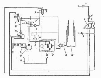
Fig. 6. Scheme of the platform lifting mechanism Kamaz-55111
1, 4 and 19 - electro-pneumatic valves; 2 - control valve; 3, 17 and 20 - pneumatic chambers; 5 - current source with voltage 24 V; 6 - fuse. 7 - power take-off switch; 8 - platform lifting and lowering switch, 9 - control lamp for power take-off switching, 10-hydraulic cylinder; 11 - valve for limiting platform lifting; 12 - filter safety valve; 13 - filter, 14 - oil tank; 15 - oil pump; 16 - power take-off; 18 - hydraulic system safety valve; 1 - lowering the platform; 11 - platform lifting
The sequence of operations when lifting and lowering the Kamaz-55111 platform is as follows (Fig. 6).
To turn on the power take-off, disengage the Clutch and put the switch 7 in the “On” position (the indicator lamp 9 will light up).
The current through the thermo-bimetallic fuse 6 is supplied to the solenoid winding of the electro-pneumatic valve 19, the core of which, moving, opens the valve.
Air from the KamAZ receiver enters the cavity of the pneumatic chamber 17 of the power take-off. When the clutch is engaged, the oil pump 15 starts to work.
Oil from the tank 14 through the suction and discharge cavity of the pump flows through the pipeline to the control valve 2, and then is drained into the tank. This circulation of oil helps to warm it up in winter, which improves the working conditions of the hydraulic system of the lifting mechanism.
To raise the Kamaz platform, turn the switch 8 to position 11. In this case, the current passes through the windings of the electro-pneumatic valves 1 and 4, the cores of which, moving, open the valves.
Air from the receiver is supplied to pneumatic chambers 20 and 3 of control valve 2. Oil from the control valve is supplied through pipelines to hydraulic cylinder 10.
Under the action of oil pressure, the links of the hydraulic cylinder are sequentially extended, raising the KamAZ platform. As the platform rises, the hydraulic cylinder tilts; when the maximum lift angle is reached, the hydraulic cylinder body presses the adjusting screw of the platform lift limiting valve 11, and the oil is drained through the valve into the tank.
Raising the platform stops.To stop the KamAZ platform in an intermediate position in the process of lifting or lowering, move the switch 8 to the neutral position. In this case, the electro-pneumatic valves 1 to 4 are turned off, the air leaves the working cavities of the pneumatic chambers 20 and 3 into the atmosphere.
The line of the hydraulic cylinder is closed, and the discharge cavity of the control valve is connected to the drain line, and the oil from the pump is drained through the control valve into the tank.
To lower the KamAZ platform, move the switch 8 to position I. The current flows to the winding of the electro-pneumatic valve 1, the core of which, moving, opens the valve.
Air from the receiver enters the pneumatic chamber 20 of the control valve. Through the control valve, the oil is drained from the hydraulic cylinder into the tank.
At the end of the lowering of the KamAZ platform, it is necessary to set switch 7 to the OFF position (after disengaging the clutch).
In this case, the oil pump stops working. It should be noted that lowering the platform is possible both when the pump is running and when the oil pump is already off, ie, switch 7 is set to the “Off” position.
The principle of operation of the mechanism for lifting and lowering the platform Kamaz-55102 is similar to the principle of operation of the mechanism for raising and lowering the platform Kamaz-55111.

Fig. 7. Scheme of the platform lifting mechanism Kamaz-55102
1-trailer hydraulic cylinder, 2-tractor hydraulic cylinder, 3-limiting valve, 4-filter safety valve, 5-filter, 6-hydraulic safety valve, 7-oil tank, 8-pump, 9 - power take-off, 10, 12, 14 - pneumatic chambers, 11, 17, 18 and 19-electro-pneumatic valves, 13 - control valve, 15 - hydraulic valve, 20- platform lifting mechanism switch, 21- control lamp, 22-hydraulic distributor switch, 23-control lamp for turning on the power take-off, 24-power take-off switch, 25-fuse, 26-24 V current source, 27-locking device, I - platform lowering, II - platform lifting
To raise the platform of the KamAZ trailer (Fig. 7), after turning on the power take-off, turn on switch 22 (when lifting the platform of the tractor, it must be turned off); the indicator lamp 21 will light up.
The current flows to the winding of the electromagnet, the core of which, moving, opens the electro-pneumatic valve 19, the air from the receiver enters the pneumatic chamber 16 of the hydraulic distributor, the hydraulic cylinder line of the tractor is closed, and the oil passage opens into the hydraulic cylinder 1 (see Fig. 7) of the trailer.
Further operations for raising and lowering the platform of the Kamaz trailer are similar to the operations for raising and lowering the tractor platform.
At the end of the work of the mechanism for lifting the platform of the trailer, it is necessary to turn off the switch 22, while the control lamp 21 will go out. Only alternate operation of the hydraulic cylinders of the tractor and the trailer is possible.
Checking the condition and correctness of regulation of the valve 4 for limiting the lifting of the KamAZ platform: the valve must be securely fixed to the subframe cross member bracket; the adjusting screw 2 must be locked with the lock nut 3.
Avoid kinking the valve stem, oil leaking from the stem seal and threaded pipe connections.
With a correctly adjusted lifting angle of the Kamaz platform, the platform locking pins should freely enter the holes in the subframe brackets. Do not operate the vehicle with impaired platform lift angle adjustment.
To adjust the platform lift angle of the KamAZ-55111 dump truck, do the following:
Unscrew the adjusting screw locknut;
Screw the adjusting screw into the stem until it stops;
Raise the platform to the position where the platform locking pins freely enter the holes in the subframe brackets and lock the platform in this position with the locking pins;
Unscrew the adjusting screw from the valve stem as far as it will go into the cylinder body and secure with a locknut.
Unlock the platform, lower and raise it again. Make sure that lifting stops when the axis of the locking pins aligns with the axis of the holes in the subframe brackets.
The deflection arrow of the safety cable should be 35 ... 50 mm. If the deflection is different, adjust the cable length by loosening the cable clamps.
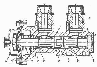
Fig. 8. The mechanism of limiting the lifting of the platform Kamaz-55102
1 and 4 - adjusting bolts; 2 and 5 - lock nuts; 3 - lever; 6 - spring; 7 - axis; 8 - restricting valve; 9 - hydraulic cylinder
To adjust the elevation angle of the KamAZ-55102 platform, do the following:
Lift the platform to the left at an angle of 48 ... 50 ° and place a technological stop under it;
Unscrew the locknut 5 (Fig. 8) of the adjusting bolt 4 and unscrew or screw in the bolt so that the nut;
In the same way, use the adjusting bolt to adjust the amount of tipping of the platform to the right, raise the platform again and make sure that its lifting is limited to an angle equal to 48 ... 500.
Pay attention to the position of the lever 3 when the platform is lowered. It should be pressed by the spring 6 against the adjusting screw of the valve 8. Otherwise, adjust the spring tension.
Lifting mechanism and sinking platformsprovides:
- raising and lowering the platform;
- stopping it in any intermediate position during lifting or lowering;
- automatic limitation of the maximum angle of ascent;
- automatic limitation of pressure in the hydraulic system.
Control lifting mechanism and the platform is lowered electropneumatically, remotely, from the driver's cab by switches installed on the instrument panel.
Lifting mechanismhydraulic consists of a power take-off box, an oil pump, a hydraulic cylinder, a control valve, a platform lifting limitation valve, electro-pneumatic valves, an oil tank with a filter and a system of pneumatic and hydraulic drives. In addition to these unified units, the platform lifting mechanism dump truck Maud. KamAZ55102 has a locking device designed to connect the hydraulic system of the tractor with the hydraulic system of the trailer, and a hydraulic valve for distributing the oil flow either to the hydraulic cylinder of the tractor or to the hydraulic cylinder of the trailer. The distributor is attached to the control valve,
Power take-off with oil pump ( fig. 269-a) is designed to take power from the gearbox and is attached to the crankcase on the right side. Between the flanges of the crankcase of the power take-off and the gearbox, sealing gaskets are installed, with the help of which the gearing of the gear wheels is adjusted. If the shims need to be replaced, their overall thickness must be maintained.
The power take-off can be turned on only when the air pressure in the car's pneumatic system is at least 490 kPa (5 kgf / cm2) and with the clutch disengaged.
Figure: 269-a. Power take-off: 1 - plug; 3.21 - gaskets; 3 - the axis of the intermediate gear; 4, 16 - washers; 5, 23 - bearings; 6 - intermediate gear; 7, 10 - retaining rings; 8 - lock washer; 9 - nut; 11 - compensator; 12 - ring; 13 - adjusting screw; 14 - power take-off case; 15 - spring; 17 - pneumatic cylinder body; 18 - sealing ring; 19 - piston; 20 - pump NSh32-L-2; 22 - half-coupling; 24 - gear
Technical characteristics of the mechanism
|
Automobile model |
KamAZ-55111 |
KamAZ-55102 |
|
Hoist control |
electro-pneumatic, remote, |
|
|
Power take-off |
from gearbox through gearbox |
|
|
Transmitted power (average), W (hp) |
||
|
Efficiency |
||
|
Oil pressure in the hydraulic system, kPa (kgf / cm2): Nominal |
||
|
maximum, limited by the safety valve |
||
|
Lifting time of loaded platform at rotation frequency |
||
|
Empty platform lowering time, s |
||
|
Fuel consumption for 100 working cycles, 1 |
||
|
Power take-off ratio |
||
|
Total gear ratio from engine crankshaft |
||
|
Pump flow at pump shaft speed |
||
|
Number of hydraulic cylinder extendable links |
||
|
Diameter of hydraulic cylinder extension, mm: |
95 |
142 |
|
Working stroke of hydraulic cylinder extendable links, mm: |
1100 |
362 |
|
The greatest effort (at oil pressure in the hydraulic system 13730 kPa) |
||
|
the first |
97,1 (9,9) |
217(22,14) |
Oil pump - high pressure gear type. The pump flow is 55.6 l / min at a speed of its shaft rotation of 1920 min-1. Thoroughly filter the oil in the tank to ensure proper operation of the pump and increase its life.
Lifting cylinder (fig. 269 \u200b\u200bb.)- telescopic, unilateral action. In the body of the hydraulic cylinder there are retractable links, the stroke of which is limited by retaining rings. The direction of the sliding links is ensured in the lower part by guides, and in the upper part by brass bushings, which are held by retaining rings. To increase the durability of the hydraulic cylinder, the outer surfaces of the extension links are knurled, chrome plated and polished.
Figure: 269-b. Hydraulic cylinder of the platform lifting mechanism of the dump truck mod. 55111: 1-branch pipe; 2-hydraulic cylinder support; 3-insert; 4 - nut; 5 - ball head; 6 - lock washer; 7 - split ring; 8 - cleaner; 9 - guide; 10 - protective ring; 11 - cuff; 12 - spacer; 13 - plunger; 14, 17 - persistent rings; 15 - hydraulic cylinder body; 16 - half rings; 18 - clamp; 19 - half ring of the holder; 20 - the bottom of the hydraulic cylinder; 21 - bolt
The retractable links are sealed with rubber cuffs located between the spacers and the protective rings. The cavity of the hydraulic cylinder is protected from the ingress of dust and dirt from the outside with wipers.
In the upper part of the hydraulic cylinder in the last plunger, a ball head is fixed, the spherical part of which forms a movable connection with the support of the hydraulic cylinder. A powder insert allows this connection to function without periodic relubrication.
At the top carmaud. 55111 there is another ball head fixed in the bottom of the hydraulic cylinder.
To the body of the hydraulic cylinder ( see fig. 269-b) dump truck Maud. 55111 a branch pipe with a threaded end is welded, and to the body of the hydraulic cylinder of a dump truck mod. 55102-fitting and trunnion for fixing it to the frame. The threaded holes of the branch pipe and the union are intended for connecting the high pressure oil line.
Control valve ( fig. 269-s) serves to control the flow of working fluid in the hydraulic system of the tipping mechanism. The seats 4, 17 of valves 18, 5 are pressed into the body 1 of the control valve and nuts 16, 10 are screwed in, serving as guides of the pushers 15, 7.
fig. 269-s. Control valve: 1 - body; 2,19,21 - fittings; 3 - sealing rings; 4, 17 - valve seats; 5, 18 - valves; 6, 13 - membranes; 7, 15 - pushers; 8, 14 - covers of pneumatic chambers; 9, 12 - springs; 10, 16 - guide nuts; 11 - sealing rings of movable joints; 20 - safety valve; B - collar; C - drainage hole
A special connection of valves with dovetail-type tappets prevents the valves from jamming in the seats in case of misalignment of the axes of the tappets and seats. Pushers with valves attached at one end at the other ends, on which membranes 13 and 6 are fixed, enter the cavities of pneumatic chambers, closed by covers 14, 8. Pusher spring 12 holds valve 18 in open position, and spring 9 presses valve 5 against the seat. The pushers are sealed with rubber rings 11, and the pusher 7, in addition, has a drain hole C. In the neutral position, oil from the pump through the pipeline through the opening of the fitting 19 enters the control valve, and passing through the open valve 18, goes to drain through the fitting 21.
When air is supplied through the hole in the cover 14 into the cavity of the pneumatic chamber above the membrane 13, the membrane moves, compressing the spring 12, and the valve 18 closes. At the same time, air is supplied through a hole in the control valve body into the cavity of the pneumatic chamber under the membrane. The diaphragm moves, compressing the spring and opening valve 5. Oil flows through valve 5 and fitting 2 into the cavity of the hydraulic cylinder. When air is released from the cavities of the pneumatic chambers, the spring 12 moves the membrane 18, and the spring 9 returns the membrane 6 to its original position. Valve 5 closes and valve 18 opens. Since valve 5 is closed, the line of the hydraulic cylinder is closed, and the platform is held in a raised position, and the oil, when the pump is running, goes from it to drain through valve 18 of the control valve.In case of an overload, the pressure in the system increases and the safety valve is triggered, passing oil into oil tank.
The platform will stop lifting until the overload is cleared. The response pressure of the safety valve is strictly adjusted at the factory, and its change during operation is not allowed.


