We learned in what modes water can move and how to determine the mode of fluid movement using the Reynolds criterion. In this article, we will learn how to determine the head loss along the length of the pipeline. This problem can be solved in two ways: make the necessary calculations by formulas manually or use special software.
Let's start with the first method. To calculate the pressure loss along the length of the pipeline, it is used darcy-Weisbach formula:
Let's solve a small problem using this formula.
Let us find the head loss along the length of the pipeline (h) when water moves with a temperature of 60 ° C in polypropylene pipe 32 * 5.4 length 10 meters at a flow rate of 14.5 l / min.
Given:
L \u003d 10 m
D (hn) \u003d 21.2 mm (0.0212 m)
Q \u003d 14.5 l / min (0.000242 m3 / s)
t \u003d 60 ° С
Liquid water
h -?
Let's consider in detail decision this task.
This problem is solved by the Darcy-Weisbach formula. However, we do not have enough data to apply this formula. We do not know the flow velocity (V) and the coefficient of hydraulic friction (λ ). The flow rate is found using the following formula:
We find the cross-sectional area of \u200b\u200bthe pipe using this formula:
R \u003d D / 2 \u003d 0.0106 m; S \u003d 3.14 * 0.0106 ^ 2 \u003d 0.000353 m ^ 2; V \u003d 0.000242 / 0.000353 \u003d 0.69 m / s ... We found the speed.
Now you need to find the coefficient of hydraulic friction ( λ). This is a little tricky. First, it is necessary to determine the mode of motion of the fluid, for this you need to find the Reynolds number by the formula Re \u003d VD / ν (read in detail in). In this formula, we do not know ν (nu) - kinematic viscosity of water. This is a tabular number (the table was given in the previous article). At water temperature 60 ° C ν \u003d 0.000000475 m ^ 2 / s. Re \u003d 0.69 * 0.0212 / 0.000000475 \u003d 30796 ... Let's check the range of values \u200b\u200bof which mode this number falls into (you can use the attached table). I checked, and the number 30796 fell into the range of values \u200b\u200bof turbulent pre-quadratic regime (second area from the table). In this mode, the coefficient of hydraulic friction(λ) calculated by the Altshul formula:
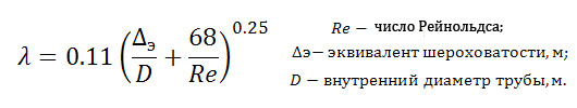
λ \u003d 0.11 * (0.00001 / 0.0212 + 68/30796) ^ 0.25 \u003d 0,025
Now we have all the data in order to calculate the head loss along the length of the pipeline using the Darcy-Weisbach formula:h \u003d 0.025 * 10 / 0.0212 * 0.69 ^ 2 / (2 * 9.8) \u003d 0.283 m... Answer: the head loss along the length of the pipeline was 0.283 meters of water column.
Now let's solve the same problem using special software. To solve the problem, we need to enter the following values \u200b\u200binto the corresponding fields of the program: water temperature, flow rate, inner diameter and pipe length. The rest of the values, including the head loss along the length of the pipeline, will be calculated by the program.

The problem in this program is solved very quickly and accurately. The value of the head losses along the length of the pipeline (linear losses), calculated by the program, coincides with the value we previously calculated manually using the formulas (0.283 m).
Recall that this issue has already been briefly mentioned in section 18 "The problem of sudden refrigerant boiling in the liquid line". To expand our knowledge in this area, we will conduct a small thought experiment using the diagrams in Fig. 75.1 and 75.2. To carry out this experiment, we need a hand-held valve on the cooling tower drain line that empties the tower when opened, and a float valve that maintains a constant water level in the cooling tower tank. At the outlet of the drain line at point B (in front of the tap), install a pressure gauge calibrated in bars. This pressure gauge will show us the pressure at point B. We will also install a glass tube that will show the pressure at point B in meters of water column (mWC), that is, the height of the water level equivalent to the pressure at point B.
In fig. 75.1 on the left (diagram 1) the valve on the drain line is closed. The water level in the tube is at a height of 5 m, that is, the pressure at point B is 5 m of water. Art. The pressure gauge at point B shows the magnitude of the excess pressure due to the high
that liquid column, that is, 5 m of water. Art. or 0.5 bar: the pressure measured by the manometer is equal to the height of the column.
In fig. 75.1 on the right (diagram 2) the drain valve is open. Under the influence of gravity, immediately after opening the tap, the water from the tank begins to drain. As soon as the water starts to move, its level in the glass tube drops to 4.5 m: therefore, the pressure loss in the section from point A to point B is 5 - 4.5 \u003d 0.5 m of water. Art. The pressure gauge at point B also shows the pressure drop by the value of the losses, which are equal to 0.5 - 0.45 \u003d 0.05 bar (i.e. 0.5 mWC). 
Hence, we conclude: as soon as the water began to move, pressure losses appeared.
These losses are due to the viscosity of the water and depend on its speed. Basically, the pressure loss is determined by the friction force of the moving water on the inner surface of the pipeline walls, which has one or another roughness.
Pressure losses grow:
with increasing pipe length;
with a drop in the inner diameter (flow area) of the pipe;
with an increase in the speed of water (that is, flow) in the pipe.
Pressure losses lead to additional energy costs. They generate pipe noises and little heating of the water. The higher the speed of the water, the more noise, especially where the flow is restricted. For example, in taps, valves, etc. This noise can cause some inconvenience in cases where pipelines are laid in residential areas or nearby.
Therefore, the diameters of the pipelines must be selected in such a way that the fluid velocity in them does not exceed certain values \u200b\u200bat the maximum required flow rates. For example, today there are such recommendations:
For pipes with an inner diameter of 15 mm, the maximum fluid velocity is 0.5 m / s.
For pipes with an inner diameter of 80 mm, the maximum fluid velocity is 1.2 m / s.
This difference in the recommended speeds is due to the following
In pipes with a diameter of 15 mm, the perimeter of the friction surface is P \u003d 1.5 cm x 7g "5 cm, the flow area is S1" 2 cm2, and in pipes with a diameter of 80 mm, the perimeter of the friction surface is P \u003d 8 cm x p to 25 cm with a flow area S2 * 50
Thus, in the transition from a pipe with an inner diameter D1 \u003d 15 mm to a pipe with a diameter D2 \u003d 80 mm
the perimeter of the friction surface increases 5 times, while the flow area increases 25 times. As a result, the friction force (and hence the pressure loss) in a pipe with a diameter of 15 mm at a flow rate of 0.5 m / s will be approximately the same as in a pipe with a diameter of 80 mm at a flow rate of 1.2 m / s. Therefore, the larger the pipe diameter, the higher the flow rate can be in it at the same friction pressure loss.
In existing installations, the diameters of liquid pipelines are chosen so that at maximum flow rate, the flow rate in them would lead to pressure losses, as a rule, in the range from 10 to 20 mm of water. Art. on running meter the length of the pipeline.
To estimate pressure losses due to local resistances (bends, tees, shut-off valves, etc.), it is common to use the concept of equivalent length. For example, it can be assumed that the pressure loss due to a 90 ° flow turn is equivalent to the frictional pressure loss on a 0.8 m long pipe section of the same diameter *.
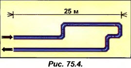
Now try to estimate the order of magnitude of the pressure loss in a pipe with an inner diameter of 65 mm and a total length of 50 m, which has 6 90 ° turns (see Fig. 75.4).
Solution to exercise 1
Provided that the pipe diameter is correctly determined, it can be assumed that the frictional pressure loss is from 10 to 20 mm wg Art. per running meter of pipe length. When making an assessment, let us assume that the friction pressure loss is equal to the average value of the specified range, that is, 15 mm of water. st./m. At the same time, 6 turns at 90 ° are equivalent in terms of pressure loss to a section of a straight pipe of the same diameter 6 x 0.8 m \u003d 4.8 m long. Therefore, the total equivalent length of our pipe will be 50 m + 4.8 m " 55 m. Thus, the total pressure loss in this pipe is 55 mx 15 mm of water. st / m \u003d 825 mm wg. st "0.8 m water. Art.
* This statement is not always true. In the general case, the length of a section of a straight pipe, equivalent in terms of pressure loss to any local resistance, is found by the formula Lekv \u003d Um / Yaltl T # D is the inner diameter of the pipe, gm is the coefficient of local losses and Mtr is the coefficient of fluid friction against the inner surface pipe walls. - Ed.
INFLUENCE OF LEVEL DIFFERENCE ON PRESSURE LOSS
Let's continue our thought experiments. In fig. 75.5 shows two absolutely identical diagrams, differing only in that the height of the cooling tower tank in diagram 1 above the drain valve is greater than the height of the tank in diagram 2.
Length drain pipes in both schemes the same, the pipe diameters are also the same. Due to the difference in levels, the pressure at point B in circuit 1 will be higher than the pressure at point B in circuit 2. Therefore, if the drain valves in both circuits are fully open, the flow rate Qvl will be higher than the flow rate Qv2. In order to compare the values \u200b\u200bof pressure losses depending on the level difference, it is necessary to close the valve of scheme 1 in order to equalize the flow rates, and, consequently, the rates of liquid flows in the pipelines of schemes 1 and 2. 
As soon as we do this, we will immediately see that if the flow rates Qvl and Qv2 are equal, the pressure losses for both schemes will exactly coincide: Ahl \u003d Ah2.
Conclusion: pressure losses due to friction and local resistances in no way depend on the difference in pipeline levels. They are determined only by the flow rate, pipeline length, inner diameter and pipe wall roughness.
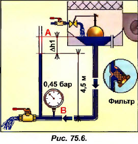
Consider the system shown in Fig. 75.6.
When water moves through the pipeline, pressure losses АЫ appear, which depend on the length of the pipeline, its diameter and water flow rate (that is, the speed of water in the pipe).
Install a filter at the outlet of the tank.
How will the pressure loss Ahl change?
How will the consumption change?
How will the speed of the water change?
Solution to exercise 2
A filter installed on the pipeline (see Fig. 75.7 on the right) behaves exactly like any local resistance (turn, valve, etc.): it is an additional obstacle to the flow of liquid, that is, it creates additional pressure losses during the passage of water. These losses are added to the friction losses. As a result, the total pressure loss in the section from point C to point B will increase (Ah2\u003e Ah 1).
 Now let's consider how the speed of water flow in the pipe will change. When installing additional resistance, for example, a filter, the pressure loss in the C-B section increases (Ah2\u003e Ah 1). But this resistance also prevents the passage of water (as would a manual valve, the resistance of which increases when it is closed): therefore, the water flow rate will decrease.
Since in this case, in both cases, the inner diameter of the pipe is section C-B does not change, a decrease in flow leads to a decrease in the flow rate of water in the pipe: the speed of V2 will be noticeably lower than the speed of VI.
With increasing pressure losses in the circuit, the fluid flow rate decreases. As the flow rate decreases, the flow rate inevitably decreases.
Pay attention to additional conditions: it should be clearly understood that the water flow rate is absolutely the same at the inlet to the filter and at the outlet from it. Since the inner diameter of the pipe is the same along its entire length, the speed will be exactly the same in every section of the pipe.
The fluid flow rate at a constant flow rate is strictly the same in each section of a pipe with a constant inner diameter.
| 75.3. EXERCISE 3. Change in flow rate when changing speed |
Water flows through a 50 m long pipe with an inner diameter of 80 mm at a speed of 1 m / s. What do you think will happen to the flow rate if the speed doubles?
Solution on next page ...
Solution to exercise 3
We will break with the tradition that operates in our guide, because here we are forced to provide simple formulas and perform very simple calculations. Please excuse us for this, but hydraulics are quite complex and sometimes you may need some basic concepts to understand some of the phenomena, which, nevertheless, we will try to explain as simply as possible.
To begin with, you should remember that the volume flow is usually measured in m3 / h or m3 / s (see chapter 41 "Air flow measurement"). 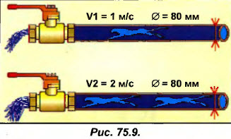
The flow rate and water flow rate are closely related:
Qv V x S
(m3 / s) \u003d (m / s) x (m2)
Flow \u003d Speed \u200b\u200bx Area
Let's calculate the flow area of \u200b\u200ba pipe with a diameter of 80 mm (see fig. 75.9): Fig. 75.9. S \u003d 3.14 x 0.082 / 4 \u003d 0.005 m2.
Now you can find the costs:
Qvl \u003d 1 m / s x 0.005 m2 \u003d 0.005 m3 / s \u003d 0.005 x 3600 \u003d 18 m3 / h.
Qv2 \u003d 2 m / s x 0.005 m2 \u003d 0.01 m3 / s \u003d 0.01 x 3600 \u003d 36 m3 / h.
Thus, for a given pipe diameter, the flow rate is directly proportional to the flow rate.
When the fluid flow rate in the pipe is doubled, the flow rate also doubles.
| 75.4. EXERCISE 4. Change in flow rate when changing pipe diameter |
We have just found that at a fluid flow rate of 1 m / s in a pipe with a diameter of 80 mm, the fluid flow rate is 18 m3 / h.
Now let's double the inner diameter of the pipe, that is, take a pipe with an inner diameter of 160 mm. What will be the liquid flow rate in this pipe at the same flow rate
Solution to exercise 4
At a flow rate of 1 m / s, the flow rate in a pipe with an inner diameter of 80 mm is 18 m3 / h. If the inner diameter of the pipe is 160 mm, then the area of \u200b\u200bits flow section will become S \u003d 3.14 x 0.1 b2 / 4 \u003d 0.02 m2. At a flow rate of 1 m / s, the flow rate in this pipe will be equal to 1 x 0.02 \u003d 0.02 m3 / s or 0.02 x 3600 \u003d 72 m3 / h instead of the previous 18 m3 / h. In other words, the consumption will grow 4 times.
Attention! Do not confuse the concept of "inner diameter" and the flow area: if the diameter doubles, then the flow area increases by 4 times!
RATIO BETWEEN FLOW AND PRESSURE
Consider a float valve designed to supply tap water to a cooling tower tank (see figure 75.11). Let us assume that a fully open valve with a water pressure in the network of 2 bar provides a flow rate of 10 l / min.
 In order to double the flow, that is, to ensure a flow through the valve equal to 20 l / min. it is necessary to increase the water pressure in the network by 4 times.
Remember! With low water pressure in the water supply network, the flow rate will be small. To double the flow, the pressure in the network must be increased 4 times.
Of course, in practice this is not done to double the flow rate. If the pressure in the network was actually increased, this would give rise to many problems: the diameter of the pipeline would have to be made very small, the water in the pipes would "hum" strongly, etc.
Let's draw the following analogy: if the highway is loaded, then in order to increase it throughput, drivers are not forced to go faster, but either make a new lane or build a bypass road! The same is done to increase the flow rate of the liquid in the pipe: the flow area of \u200b\u200bthe pipe is increased.
At a given flow rate, this leads to a decrease in the water flow rate in the pipe (and, therefore, noise), and the pressure required to ensure this flow rate decreases
RELATIONSHIP BETWEEN FLOW RATE AND PRESSURE LOSS
In a pipe with an inner diameter of 80 mm, the flow rate is supposed to be doubled. What happens to the pressure loss? At first glance, it might seem that since the flow rate doubles when the flow rate is doubled, the pressure loss should also double. Unfortunately, this is not so.
When the flow rate is doubled, the losses are not doubled, but quadrupled: if the flow rate doubled, the pressure loss would quadruple!
In the example in Fig. 75.13 at a flow rate of 1 m / s, pressure loss AP \u003d 2 m water. Art., and with an increase in speed to 2 m / s, the pressure loss is multiplied by 4: AP \u003d 2 x 4
The pressure loss is proportional to the square of the flow rate.
For more information, see Section 95 "Some Examples of Calculating Pressure Loss".
Shown is a section of the pipeline that passes water at a speed of I m / s. Pressure gauges show the pressure at various points in this pipeline. The following conclusions can be drawn from the readings of the manometers.
At a water flow rate of 1 m / s, the pressure loss is:
- on the ARf filter \u003d 2 - 1.8 \u003d 0.2 bar;
- on the ARv valve \u003d 1.8 - 1.7 \u003d 0.1 bar.
What will the pressure gauges at the outlet of the filter and at the outlet of the valve show if the flow rate in the pipe doubles? The solution to this exercise is shown below, but before you try it, try thinking for yourself.
Solution to exercise 5
The speed has doubled, therefore the flow rate has also doubled. As a result of the pressure loss on
filter and valve will grow 4 times.
Now the pressure loss across the ARf filter \u003d 0.2 bar x 4 \u003d 0.8 bar, that is, the pressure gauge at the outlet
from the filter will show 2 - 0.8 \u003d 1.2 bar.
Pressure loss across the APv valve \u003d 0.1 bar x 4 \u003d 0.4 bar, that is, the pressure gauge at the outlet
valve will show 1.2 - 0.4 \u003d 0.8 bar.
Note that the total pressure loss in this section will increase from 0.3 to 1.2 bar: that is, also 4 times.
Each person who decides to independently equip the water supply of his home should be prepared for such a problem as reducing the pressure inside the system. As a rule, the reason lies in the fact that the total water pressure in the pipe falls: that is why the selection of the power of the borehole pump must be carried out with special care.
Why does the pressure drop in the water supply
When fluid moves through the pipeline, it encounters certain obstacles in its path.
The internal resistance of the water supply system is influenced by the following factors:
- Internal pipe diameter. Its decrease is directly proportional to the increase in resistance.
- The speed of movement of water in the system. The larger it is, the stronger the resistance.
- Features of the pipe coating that is in direct contact with water. Pressure losses in the pipeline can occur due to excessive roughness of the inner surface.
It should be said that even if we are talking about the transportation of water through a straight pipe, a certain inhibition of its flow is still observed. The more the length of the conduit increases, the more the indicator of total resistance increases.
Pressure loss in straight lines
To accurately make the necessary calculations, it is most convenient to use special tables and formulas: they will allow you to get the most accurate parameters. It should also be taken into account that recently, supply water pipes are mainly assembled from polymer pipes. The pressure drop in a pipeline of this type is observed on a much smaller scale.

These products offer the following operational benefits:
- Light weight and convenient installation.
- Anti-corrosion safety.
- Excellent smoothness characteristics of the polymers used for the manufacture of these pipes. This makes it possible to significantly reduce the internal resistance of the system. According to this parameter, plastic water conduits are about 1.5 times more profitable than metal analogues.
How to account for local resistance
Along with linear losses inside pipelines, there may be so-called “local” resistances. First of all, we are talking about elements that provide branching and flow power control - tees, taps, valves, elbows, valves, etc. The loss parameters within these products are influenced by the fluid flow rate and their configuration.
The formula by which the internal resistance is calculated
How to determine the head loss in the pipeline? Water consumption is determined by the following formula: Q \u003d V × S. The water flow rate is designated here as "Q" (m3 / s), the cross-sectional area of \u200b\u200bthe pipe as "S". The letter "V" (m / s) is used here to represent speed. To calculate the cross-sectional area, the classical formula S \u003d π × D2 / 4 is used, where "D" refers to the diameter of the water pipe.
When the calculations of the required values \u200b\u200bare completed, one can come to the conclusion that the local resistance indicators are scanty when compared with the total (total) losses, regardless of which samples are used. The resistance of water in pipes may increase slightly if the flow rate is increased: this is due to the fact that the water channel begins to pass a large volume of water through its narrow part.
Losses of water in pipelines can increase to significant levels. To prevent this from happening, it is recommended to initially complete the water pipes with products with a large diameter: subsequently, some additional financial expenses are more than compensated for. This will make it possible to completely abandon the consideration of local resistance. If we talk about general situations, then the parameters of losses in the water supply system are calculated taking into account the flow rate of 2-4 m3 of liquid for local resistances. When it is necessary to take into account losses during the passage of straight sections, the level of total losses can reach about 5 m3.


