The amount of displacement (compensating capacity) of expansion joints is usually expressed as a combination of positive and negative numerical values \u200b\u200b(±). A negative (-) value indicates the allowable compression of the expansion joint, a positive (+) value indicates its allowable expansion. The sum of the absolute values \u200b\u200bof these values \u200b\u200bis the total offset of the compensator. In most cases, expansion joints work in compression, compensating for thermal expansion of pipelines, less often (refrigerated media and cryogenic products) - in tension.
Pre-stretching during installation is necessary for the rational use of the full displacement of the compensator, depending on the nature of the pipeline, installation conditions and prevention of stress conditions.
Peak values \u200b\u200bof pipeline expansion depend on the minimum and maximum operating temperatures. For example, the minimum operating temperature of the pipeline is Tmin \u003d 0 ° C and the maximum T max \u003d 100 ° C. Those. temperature difference At \u003d 100 ° C. With a pipeline length L equal to 90 m, the maximum value of its pipeline elongation AL is 100 mm. Imagine that for installation on such a pipeline, expansion joints with an offset of ± 50 mm are used, i.e. with a full offset of 100 mm. Also imagine that the temperature environment at the stage of their installation, T y is equal to 20 ° C. The nature of the compensator operation under such conditions will be as follows:
- at 0 ° С - the expansion joint will be stretched by 50 mm
- at 100 ° С - the expansion joint will be compressed by 50 mm
- at 50 ° С - the compensator will be in a free state
- at 20 ° C - the expansion joint will be stretched by 30 mm
Therefore, preliminary stretching by 30 mm during installation (T y \u003d 20 ° C) will ensure its efficient operation. When the temperature rises from 20 ° C to 50 ° C during the commissioning of the pipeline, the compensator will return to a free (unstressed) state. When the temperature of the pipeline rises from 50 ° C to 100 ° C, the displacement of the compensator relative to the free state towards the compression side will be calculated 50 mm.
Definitionmeaningpreliminarystretching
Let's take the length of the pipeline equal to 33 meters, maximum / minimum operating temperature + 150 ° С / -20 ° С, respectively. With such a temperature difference, the coefficient of linear expansion a will be 0.012 mm / m * ° C.
The maximum elongation of the pipeline can be calculated as follows:
ΔL \u003d α * L *Δ t = 0.012 x 33 x 170 \u003d 67 mm
The pre-stretch PS is determined by the formula:
PS \u003d (ΔL / 2) - ΔL (Ty-Tmin): (Tmax-Tmin)
Thus, during the installation of the expansion joint, it must be installed with a pre-tension PS equal to 18 mm.
|
|

In fig. 1 shows the distance required for the installation of the expansion joint in the pipeline line, determined as the sum of the values \u200b\u200bof the expansion joint length lq in the free state and the pre-tension PS.
In fig. 2 shows that during installation, on one side, the expansion joint is fixed with a flange or welded.
Heat network compensators. This article will focus on the selection and calculation of expansion joints for heating networks.
What are compensators for? Let's start with the fact that when heated, any material expands, which means the pipelines of heating networks lengthen when the temperature of the coolant passing through them rises. For trouble-free operation of the heating network, expansion joints are used that compensate for the elongation of the pipelines when they are compressed and stretched, in order to avoid pinching the pipelines and their subsequent depressurization.
It is worth noting that for the possibility of expansion and contraction of pipelines, not only expansion joints are designed, but also a system of supports, which, in turn, can be both "sliding" and "dead". As a rule, in Russia, heat load regulation is of high quality - that is, with changes in the ambient temperature, the temperature at the outlet of the heat supply source changes. Due to the high-quality regulation of heat supply, the number of expansion-contraction cycles of pipelines increases. The resource of pipelines is reduced, the risk of pinching increases. Quantitative load regulation is as follows - the temperature at the exit from the heat supply source is constant. If it is necessary to change the heat load, the flow rate of the coolant changes. In this case, the metal of the heating network pipelines works in lighter conditions, the expansion-compression cycles are minimal, thereby increasing the resource of the heating network pipelines. Therefore, before choosing expansion joints, their characteristics and quantity must be determined with the amount of pipeline expansion.
Formula 1:
δL \u003d L1 * a * (T2-T1) where
δL - the amount of pipeline elongation,
mL1 - length of the straight section of the pipeline (distance between fixed supports),
ma - coefficient of linear expansion (for iron it is 0.000012), m / deg.
T1 is the maximum temperature of the pipeline (the maximum temperature of the coolant is taken),
T2 - the minimum temperature of the pipeline (you can take the minimum ambient temperature), ° С
As an example, let us consider the solution of an elementary problem to determine the length of the pipeline elongation.
Task 1. Determine how much the length of a straight section of the pipeline 150 meters long will increase, provided that the temperature of the coolant is 150 ° C, and the ambient temperature during the heating season is -40 ° C.
δL \u003d L1 * a * (T2-T1) \u003d 150 * 0.000012 * (150 - (- 40)) \u003d 150 * 0.000012 * 190 \u003d 150 * 0.00228 \u003d 0.342 meters
Answer: the length of the pipeline will increase by 0.342 meters.
After determining the amount of elongation, you should clearly understand when you need and when you do not need a compensator. For an unambiguous answer to this question, you need to have a clear pipeline diagram, with its linear dimensions and supports applied to it. It should be clearly understood that a change in the direction of the pipeline is able to compensate for the elongations, in other words, a turn with dimensions not less than the dimensions of the compensator, withcorrect the placement of supports, is able to compensate for the same elongation as the expansion joint.
And so, after we have determined the length of the pipeline elongation, we can proceed to the selection of expansion joints, you need to know that each expansion joint has the main characteristic - this is the compensation value. In fact, the choice of the number of expansion joints comes down to the choice of the type and design features of the expansion joints. determine the pipe diameter of the heating network based on bandwidth pipes and the required power of the heat consumer.
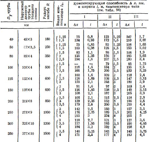
Table 1. Ratio of U-shaped expansion joints made of bends.
Table 2. Selection of the number of U-shaped expansion joints based on their compensating capacity.
Task 2 Determination of the number and size of expansion joints.
For a pipeline with a diameter of DN 100 with a straight section length of 150 meters, provided that the temperature of the carrier is 150 ° C, and the ambient temperature during the heating period is -40 ° C, determine the number of expansion joints. BL \u003d 0.342 m (see Task 1). According to Table 1 and Table 2 we determine the dimensions of n-shaped expansion joints (with dimensions of 2x2 m can compensate for 0.134 meters of pipeline elongation), we need to compensate for 0.342 meters, therefore Ncomp \u003d bL / ∂x \u003d 0.342 / 0.134 \u003d 2.55, round to the nearest integer in side of the increase and that - 3 compensators with dimensions of 2x4 meters are required.
Currently, lens compensators are becoming more widespread, they are much more compact than U-shaped ones, but a number of restrictions do not always allow their use. The resource of the U-shaped expansion joint, provided that the quality of the coolant leaves much to be desired, is much higher than that of the lens one. The lower part of the lens expansion joint is usually "clogged" with sludge, which contributes to the development of parking corrosion of the expansion joint metal.
Expansion joint installation technology.
1.1. general information about compensators.
All pipelines are subject to temperature deformations when the temperature of the transported product and the environment changes. Linear elongation of 1m of a pipeline when it is heated by 1 ° C is called the linear elongation coefficient.
Since the pipelines are long, their total elongation can reach large values.
Thermal elongation of the pipeline section? L is determined by the formula:
Due to thermal elongation, significant longitudinal forces arise in the pipeline, which exert pressure on the end fixed points (supports), trying to move them from their place. These forces are so significant that they can destroy the supports, cause longitudinal bending of the pipeline (Fig. 1, a), or lead to disruption of flanged and welded joints.
To protect the pipeline from additional loads arising from temperature changes, it is designed and constructively executed so that it can freely lengthen when heated and shorten when cooled without overstressing the material and pipe connections. The ability of a pipeline to deform under the influence of thermal elongations within the limits of permissible stresses in the pipe material is called thermal elongation compensation. The ability of a pipeline to compensate for thermal elongations due to the elasticity of the line section structure and the elastic properties of the metal, without special devices built into the pipeline, is called self-compensation.
Self-compensation is carried out due to the fact that in the pipeline line, in addition to straight sections, there are turns or bends (bends) between the fixed supports. A turn or bend located between two straight sections compensates for a significant part of the elongation due to the elasticity of the structure, and the rest is compensated for due to the elastic properties of the metal of the straight section of the pipeline.
When self-compensation of pipelines cannot be used in the design and installation, or it is insufficient to protect the pipeline from the forces arising from thermal elongation, special devices called expansion joints are installed.
Depending on the design, the principle of operation, expansion joints are divided into four main groups: U-shaped, lens, wavy and stuffing box.
U-shaped expansion joints have a large compensating capacity (up to 600-700 mm) and are used in pipelines for a wide range of pressures and temperatures. U-shaped expansion joints are most widely used in technological pipelines due to the relative ease of their manufacture in operation. Their disadvantages are high pipe consumption, large overall dimensions and the need to build special support structures.
U-shaped expansion joints are especially uneconomical for pipelines of large diameters, since they significantly increase the cost of construction and increase pipe consumption.
U-shaped expansion joints are made completely bent from one pipe or welded using bent, steeply bent or welded bends. Bent and welded expansion joints with steeply bent branches can be installed on pipelines for any pressure and temperature. At the same time, the compensating ability of pipelines with steeply curved branches is higher than that of bent ones, due to longer straight sections.
U-shaped expansion joints made of welded bends are used for pipelines with a nominal diameter of not more than 500 mm. For pipelines of steam and hot water, such compensators can be used on pipelines of III and IV categories for nominal pressure up to 64 kgf / cm2.
U-shaped expansion joints, as a rule, are installed in a horizontal position, observing the required slope of the gas pipeline. With a limited area, expansion joints can be installed in a vertical and inclined position with a loop up or down, while they must be equipped with drainage devices and air vents.
For pipelines requiring disassembly for cleaning, U-shaped expansion joints are manufactured with connecting ends on flanges.
The design of U-shaped expansion joints and their dimensions must be indicated in the project.
They consist of a number of lenses connected in series in the pipeline. The welded construction lens consists of two thin-walled stamped steel half lenses, and due to its shape it is easy to compress. The compensation capacity of each lens is relatively small (10-16mm). The number of compensator lenses is selected depending on the required compensating capacity. To reduce the resistance to the movement of the product, glasses are installed inside the compensator. For drainage of condensate at the lowest points of each lens, drain fittings are welded. Lens compensators are used for the discharge pressure up to 6 kgf / cm2 at temperatures up to + 450 ° C. They are installed on gas pipelines and steam pipelines with a diameter of 100 to 1600 mm.
The advantage of lens compensators over U-shaped ones is their small size and weight; disadvantages - small allowable pressures, small compensating capacity and large longitudinal forces transmitted to fixed supports.
Wavy expansion joints are the most advanced expansion joints. They have a large compensation capacity, small dimensions and can be used at relatively high pressures and temperatures.
A distinctive feature of corrugated expansion joints in comparison with lens expansion joints is that the flexible element is a thin-walled corrugated steel high-strength and elastic shell. The wave profile is omega or U-shaped so that the flexible member can contract or lengthen and bend when a load is applied. The technology of manufacturing a flexible element of the compensator is based on the principle of hydraulic drawing (shaping) of waves in a cylindrical shell with a draft of its height (for this purpose, special hydraulic presses are used).
Wavy axial expansion joints KVO-2 are installed on straight sections of pipelines and at bends.
Wavy universal articulated expansion joints KVU-2 and KVU-3 are installed in U-shaped, Z-shaped and angular articulated pipeline systems, 2-3 in each system.
KVSH hinged double expansion joints are installed in corner, Z-shaped and U-shaped systems and on branches.
KVU and KVSh compensators are installed in pipeline sections with significant temperature differences or at large distances between rigid supports, to which relatively small forces are transferred.
Wavy expansion joints are designed to operate at temperatures from -40 to + 450 ° C.
The technical characteristics of corrugated expansion joints are shown in table 1.
It consists of two nozzles inserted into one another. A stuffing box seal with a packing follower is installed in the gap between the branch pipes.
Gland expansion joints have a high compensating capacity, small dimensions, but due to the difficulty of sealing gland seals in process pipelines, they are rarely used, and they cannot be used for pipelines of combustible, toxic and liquefied gases.
The main disadvantages of stuffing box expansion joints are as follows: the need for systematic monitoring and maintenance of them during operation, the relatively rapid wear of the stuffing box packing and, as a result, the lack of reliable tightness.
Stuffing box expansion joints are installed on water, steam and heat pipelines, as well as on pipelines transporting non-combustible liquids. Due to their small size, they can easily be placed in chambers and walk-through tunnels. Steel stuffing box expansion joints are used for nominal pressure up to 16 kgf / cm2, and cast iron (made of gray cast iron grade not lower than Сч 15-32) - up to 13 kgf / cm2 at temperatures not higher than 300оС. By design, stuffing box expansion joints are divided into one-sided and two-sided, unloaded (not creating a large axial force on fixed supports) and unloaded. The expansion joints are connected to the pipeline by welding or on flanges.
1.2. installation of expansion joints.
Before installing expansion joints in design position it is necessary to control them by external examination. As a rule, before the final connection to the pipeline, all expansion joints must be pre-stretched or compressed by the amount specified in the project and installed on the pipelines together with a spacer (or compression) device, which is removed only after the final fastening of the pipelines to fixed supports. The amount of prestretching of the expansion joint is indicated in the drawings.
Stretching is used for “hot” pipeline lines, and compression is used for “cold” ones. The operation of stretching or compressing is called cold stress on the pipe and is performed in order to reduce the stress in the metal during thermal expansion of the pipe.
An act is drawn up on the expansion of expansion joints, regardless of the method of its implementation, in which the construction lengths of the expansion joints are indicated before and after the expansion.
U-shaped compessers are usually installed horizontally and only vertically or obliquely as an exception. When installing such expansion joints vertically or obliquely, at the lower points on both sides of the expansion joints, it is necessary to place drainage nipples for condensate drainage, and in the upper part - air vents.
To ensure normal operation, the U-shaped expansion joint is installed on at least three movable supports (Fig. 5). Two supports are placed on straight sections of the pipeline connected to the compensator (while the edge of the support must be at least 500 mm away from the welded joint), the third support is placed under the back of the compensator, usually on a special column.
For preliminary stretching of the U-shaped compensator, a screw device is used, consisting of two clamps, between which a screw and a spacer with a tension nut are installed.
Before stretching, measure the length of the compensator in a free state, and then, by rotating the nut, dilute it to the required amount. The spacer is installed parallel to the back of the compensator. The joint at which the expansion joint will be stretched is indicated in the project. If there is no indication, then in order to avoid skewing, the joint cannot be used for stretching. Directly adjacent to the expansion joint. For this purpose, you need to leave a gap in the adjacent joint.
When lifting, the expansion joints must be gripped at three points and never by the spacer. Only after tacking the joints and sealing the compensator is disconnected from the lifting equipment. It is also necessary to check the reliability of the installation of the spacer.
U-shaped expansion joints are installed in the design position using one or two cranes.
With the group arrangement of U-shaped expansion joints of parallel pipelines (one inside the other) and in some other cases, the preliminary stretching of the expansion joints is replaced by the tension of the pipeline in a cold state. In this case, when installing expansion joints, the pipeline is assembled in the usual way, but in one of the joints (welded or flanged), a gap is left equal to the specified value of the expansion joint expansion.
Before stretching, make sure that all welded joints in this section of the pipeline are welded, the fixed supports are finally fixed.
When installing expansion joints without preliminary stretching, for the convenience of installing the pipeline, a branch pipe with a length equal to the size of the stretch is inserted into the joint, which is intended for stretching, and tacked by electric welding to both edges of the pipeline. Sometimes, annular beads are fused at the ends of the pipes to be joined and temporary clamps are installed from the corners. Elongated tie rods are passed through the holes in them and, tightening the nuts, clamp the temporary spacer insert ring installed between the ends of the joint. After welding the joint, the clamps are removed.
The flange joint, left for stretching, is temporarily (without permanent gaskets) pulled together with elongated studs, installing them through one and leaving holes for permanent bolts. The diameter and number of cold tensioning studs are specified in the project.
After installing the expansion joints in the design position, welding all joints (except one) and securing the pipeline on all fixed supports on both sides of the expansion joint, remove the temporary spacer ring and tighten the joint for welding by tightening the nuts on the elongated studs. In case of flange connection, the gasket provided by the project is installed before the final tightening. After tightening the flange connection with permanent bolts, the elongated studs are removed, and permanent bolts or studs are installed in their place.
When installing the lens expansion joints, it is necessary to ensure that the drain connectors (if any) are in the lower position, and the expansion joint guide cup is welded in in the direction of product movement.
Lens expansion joints are recommended to be installed on pipes, assemblies or blocks before lifting to the design position. The assembled unit or block with lens compensators must be protected from deformation and damage during transportation, lifting and installation. For this, additional stiffness is used on the expansion joints. After installing the nodes on the supports and fixing the temporary stiffnesses are removed.
When installing vertical sections of pipelines, it is necessary to take measures to exclude the possibility of compression and defomation of expansion joints under the influence of gravity of the pipelines. For this, in parallel to the expansion joints on the pipelines, three brackets are welded, which are cut off at the end of the installation of the pipeline.
Lens expansion joints are stretched by half of their compensating capacity.
The lens expansion joint is stretched during installation after its welding or final connection on flanges with a pipeline, as well as after installing all supports and suspensions of pipelines and fixing pipelines in fixed supports.
In this case, the expansion joint is stretched by tightening the assembly joint closest to the expansion joint, in which a corresponding additional gap is specially left.
The compression of the expansion joint is carried out after the final connection with the pipeline, but before it is fixed on fixed supports. To compress or stretch the lens expansion joint, a device is used that consists of two clamping clamps fixed to the pipeline on both sides of the expansion joint, and elongated clamping rods with nuts.
When installing several lens expansion joints on the pipeline, the project must provide fixed supports behind each expansion joint in order to exclude the possibility of deflection of the pipeline in a compressed state and to ensure more uniform deformation of all expansion joints installed on the pipeline, since the actual stiffness of all expansion joints can be different.
For wavy expansion joints, check the headroom before installation; using spacers and pins, set the gap corresponding to the preliminary stretching.
Axial expansion joints are mounted in the following sequence. First, they are welded at one end to the pipeline. Between the second end and the pipe to be welded, check the gap equal to the pre-stretching value, stretch the expansion joint using the nuts with studs on it, weld the second end of the expansion joint to the pipeline, and then remove the studs and nuts.
When installing hinged or universal expansion joints, they are welded to the pipeline with both ends in accordance with the installation diagram, without removing the bolts holding the hinge cheeks and protecting the expansion joint from bending.
During installation, stuffing box expansion joints must be installed strictly in line with the pipeline, without distortions in order to avoid jamming of moving parts and damage to the expansion joint packing. Guiding devices of pipelines at the points of connection to stuffing box expansion joints must tightly compress the pipes with rollers fitted to them and center the pipe in horizontal and vertical surfaces, without creating large longitudinal frictional forces.
Gland expansion joints are not stretched after installation, since when the expansion joint is welded to the pipeline, it is pushed apart by the amount specified in the project and determined by the distance between the risks applied to its body and glass. In this case, a gap must be left between the thrust rings on the branch pipe and in the compensator housing in case the temperature drops in comparison with the air temperature at the time of installation. The minimum clearance value for a pipeline section length of 100mm should be 30mm at an outside air temperature at the time of installation below -5oC, 50mm from -5oC to + 20oC, 60mm above + 20oC. During installation, it is necessary to ensure that in the event of a breakdown of the fixed supports, the moving part of the pipe does not break out of the compensator body. In most cases, for this, a rim is welded onto the sliding part of the pipe so that it does not interfere with the operation of the compensator.


