Recently, retro-inspired watches with gas-discharge indicators have become very popular. In foreign countries such watches are called “Nixie-clock”. Having seen a similar project on the Internet, I was inspired by the idea of assembling the same ones for myself.
Read on to find out what came of it.
I studied the circuit options on the Internet. Typically, a Nixie watch consists of four main parts:
1. control microcontroller,
2. high voltage power supply,
3. driver-decoder and lamps themselves.
In most circuits, Soviet K155ID1 microcircuits are used as a decoder - “high-voltage decoders for controlling gas-discharge indicators.” I couldn’t find such a chip, and I didn’t really want to use DIP packages.
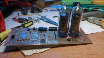
Clock diagram, parts used
Taking into account the available components, I developed my own version of the clock circuit, in which the role of the decoder is assigned to the microcontroller.
Figure 1. Scheme of Nixie clock on MK
On the U4 MC34063 chip, a boost “dc-dc” converter with an external key on the IRF630M is assembled in a completely isolated case. The transistor was taken from the monitor board.
R4+Q1+D1 are a simple switch driver, quickly discharging the shutter. Without such a driver, the key got very hot and it was impossible to get the required voltage.
R5+R7+C8 - feedback that determines the output voltage at 166 Volts. Transistors Q3-Q10 together with resistors R8-R23 make up the anode switches, allowing for dynamic display.
Resistors R8-R11 set the brightness of the indicator numbers, and resistor R35 sets the brightness of the dividing point.
The same terminals of all lamps with the exception of the anode are connected to each other and controlled by transistors Q11-Q21.
The ATMEGA8 microcontroller controls the lamp switches, and it also polls the DS1307 real-time clock (RTC) chip and buttons.
Diodes D3 and D4 ensure the generation of an external interrupt request by pressing any of the control buttons.
The controller is powered through a 78L05 linear stabilizer.
IN-14 lamps are glow discharge indicators.
Cathodes in the form of Arabic numerals with a height of 18 mm and two commas. Indication is carried out through the side surface of the cylinder. The design is glass, with flexible leads.

So to speak, uh... the Iskra 122 calculator. Photo ~MERCURY LIGHT~
The IN-14 indicators from the monstrous Iskra 122 calculator from 1978 shine without problems and I got it for “thank you for clearing my balcony.”
The structure can be powered with a constant voltage of 6 - 15 Volts from an external power supply. Consumption of less than one watt (70 mA at 10 V).
To keep the clock running during power failures, a CR2032 battery is provided. According to the datasheet, the DS1307 consumes only 500nA when running on battery power, so this battery will last for a very long time.
Clock management
After power is applied, four zeros will light up, and if communication with the DS1307 chip is established without errors, the dividing dot will begin to blink.The time is set using three buttons “+”, “-” and “set”. Pressing the “set” button will extinguish the hour digits, then use the “+” and “-” buttons to set the minutes. The next press of the “set” button will switch to the clock setting mode. Another press of “set” will reset it to 0 seconds and switch the clock to the “HH:MM” time display mode. The dividing dot will flash.
By holding the "+" button, you can view the current time in the "MM:SS" mode at any time.
Pay
All main parts of the circuit are connected to one double-sided board measuring 135x53 mm. The board was made by LUT and etched in hydrogen peroxide with citric acid. The layers of the board were connected to each other by soldering pieces of copper wire into the holes.The board templates were aligned to the light along the marks outside the board. It is worth recalling that the top layer of M1 in Sprint-Layout must be printed in mirror image.
During the test assembly, “jambs” were identified in the wiring. I had to connect the anode transistors with wires. The printed circuit board in the archive for the article has been corrected.
Contact pads are provided for programming the controller.
Photo of the assembled clock board

Photo 1. Clock board from below

High voltage electric The capacitor is placed horizontally; I made a cut for it in the PCB. I tried to make the assembled board as miniature as possible. It turned out to be only 15 mm thick. You can make a thin, stylish case!

Parts List

Files
The archive contains a high-resolution clock diagram, a printed circuit board in SL5 format and firmware for the controller.The fuses must be configured to operate from an internal 8 MHz oscillator.
▼ 🕗 05/24/15 ⚖️ 819.72 Kb ⇣ 137 Hello, reader! My name is Igor, I'm 45, I'm a Siberian and an avid amateur electronics engineer. I came up with, created and have been maintaining this wonderful site since 2006.
For more than 10 years, our magazine has existed only at my expense.
Good! The freebie is over. If you want files and useful articles, help me!
Lamp : IN-14
Scheme: There is
Pay: No
Firmware: There is
Source: No
Description: There is
Peculiarities: author's development from Myxomop.
Scheme:
Watch of our own design. There is an alarm clock and a service menu where you can change the clock settings. You can turn on the “strike” - when the hour changes, the clock beeps the number of hours.


The power supply is the simplest switching one. I did it according to this scheme

You can see my mistake on the board near the crystal oscillator. I'm used to controllers, like everything can be changed programmatically. And here the outputs of the decoder (hard logic) control the keys, I didn’t even think about this when developing the circuit, you need to send 1 or 0. I connected the outputs of the decoder with the keys purely automatically. Then I spent a long time looking for an error in the program. When it finally dawned on me what was wrong, I cursed for half a day.


When all the jambs (both hardware and software) were fixed, we got a watch like this.

Let me briefly list the functions of the service menu:
1
- on(1)/off(0) battle
2
- on(1)/off(0) show insignificant "0" in the most significant digit of the clock
3
- 12/24 hour cycle of time display (if a 12-hour cycle is selected, when setting the time, the clock automatically switches to a 24-hour cycle and then returns back)
4
- 4 options for flashing the dividing point
5
- 4 sound options for the alarm clock (you can listen to the sound using the “Set” button)
6
- number of cycles of alarm clock sound playback (1-99)
7
- correction number for timing
8
- on(1)/off(0) smooth change of numbers
9
- writing settings to the eeprom (happens once each time you enter this menu item, while the flashing “0” is set to “1”)
You can enter the service menu by pressing the “Set” and “Mode” buttons simultaneously. The "Set" button must be pressed first. The output is the same.
If the clock is not accurate enough, you can try changing the correction number in the service menu. You can calculate it like this. First we write 0 there. And leave it for exactly one day. During this time, the clock must run forward. If they are behind, then no correction will help, most likely the reason is in the quartz - just change it! So, let's look at how many seconds they went ahead ( sec) we calculate this number approximately using the formula korr=43.2/sec. Then you can detect it again a few days in advance and try changing it to +/-1 and see if there are any improvements.
Well, if you decide to repeat my design, I’ll post the firmware.
Firmware .
The only crap that we couldn’t overcome was the ringing (squeaking) of indicators from the dynamic display. Judging by the experience of other nixy builders, there is nothing to be done about this, such is the design of the lamps themselves.
Hello, dear readers. For a long time I wanted to assemble a clock with gas-discharge indicators, but I was sorely short of time, I finally finished this project. Below the cut is a little about what gas-discharge indicators are, as well as about how I assembled the watch, starting with the circuit and ending with the case.
Introduction
According to Wikipedia, the first gas-discharge indicators were developed in the 50s of the last century. Abroad, such indicators are called “Nixie”, the name comes from the abbreviation “NIX 1” - “Numerical Indicator eXperimental 1” (“experimental digital indicator, development 1”). This watch uses iconic Soviet-made indicators such as IN-12B.
By design, they are a glass flask inside of which there are ten thin metal electrodes (cathodes), each of which corresponds to one number from 0 to 9, the electrodes are folded so that different numbers appear at different depths. There is also one electrode in the form of a metal mesh (anode), located in front of all the others. The flask is filled with the inert gas neon with a small amount of mercury. When an electrical potential of 120 to 180 volts DC is applied between the anode and cathode, a glow occurs near the cathode and the corresponding number lights up. These indicators are valued for this soft orange light.
Additional Information
To be precise, IN-12B lamps have one more cathode - in the form of a point; it is not used in these watches.
Also in this watch, another gas-discharge indicator is used to separate hours and minutes - INS-1  The indication is carried out through the lens dome of the cylinder and looks like a luminous orange dot.
Scheme
The clock diagram was found on the Internet, author Timofey Nosov. It is based on the PIC16F628A microcontroller and the Soviet K155ID1 microcircuit, which is a high-voltage decoder for controlling gas-discharge indicators.
The lamps are powered using a boost pulse converter assembled on a field-effect transistor, inductor, capacitor and diode; the PWM signal is generated by a microcontroller. This circuit uses dynamic indication; the microcontroller, using the K155ID1 decoder, controls the cathodes of all lamps at once, and synchronously controls the anodes of the lamps through optocouplers. The lamp switching speed occurs at a high frequency, and since gas-discharge indicators, like any lamp, need time to go out, the human eye does not see the flickering (I will say more - even the camera does not see it).
The circuit implements backup power using the CR2032 element; when the power is turned off, the indication goes out and the clock continues to run.
Electronic part
The clock circuit is divided into two parts - a board with lamps and the main board of the device. Link to archive with file for Splint Layout -
 Using LUT I made two boards 
Assembling the board with lamps 
 I got the lamps from old Soviet equipment, and it was this find that prompted me to collect these watches.
Assembling the main board 

The boards are connected via PLS and PBS connectors, which are soldered on the track side. This is what it looks like assembled: 
 I bought a PIC16F628A microcontroller -
I bought optocouplers -
Field effect transistor IFR840 -
The rest was in stock or found locally.
All that remains is to flash the microcontroller. We will flash it using the PICkit2 programmer, which we bought a long time ago - 
We launch the PICkit2 program and flash our microcontroller  After flashing the firmware, I turn on the watch... but the numbers do not light up, only the second indicator (INS-1) blinks. After I found my mistake, a 47K resistor was installed in the lamp power circuit instead of a 4.7K resistor. After the replacement, the circuit started working, we need to make a housing.
Frame
I still have a piece of beech timber left, this is the same beech that was used to make the body of the “shaitan box” from my .
At first I wanted to cut out the body on a CNC machine, I agreed with my friend who works in furniture production. But, as it happens, sometimes there is no time, then other work urgently needs to be done. In short, after a month of waiting, I decided to do it myself.
I cut out a blank for the future body, marked it 
I cut out a cavity for the insides, this was a labor-intensive step itself. First I drilled it out, then I removed the excess with a chisel, and then I sanded it. 
Using a chisel, I made a recess for the glass and the back panel, glued the stops inside the case, and soaked everything in linseed oil. 

I cut out a piece of the required size from darkened glass. 
I made a back panel with holes for buttons and a power connector 
Put it all together, front view 
Back view 
In order for the clock to stand slightly at an angle, I glued two rubber feet to the bottom. 
In the case of rare switching on of individual indicator cathodes and the activity of others, particles of metal sputtered by working cathodes settle on rarely used ones, which contributes to their “poisoning”. The device implements a method to combat this phenomenon; before changing the minutes, all numbers in all lamps are quickly searched. Demonstration of how this happens: 
From the functionality - clock, alarm clock, brightness adjustment. Control is carried out by three buttons - “more”, “ok” and “less”.
By pressing the “ok” button you can cycle through the following modes:
– setting the current time clock (HH _ _);
– setting the minutes of the current time (_ _ MM);
– setting the alarm clock (HH._ _);
– setting the alarm minutes (_ _.MM);
– setting the current day of the week from 1 to 7 (0 _ _ 1);
– alarm goes off on Monday (1 _ _ 1);
– alarm goes off on Tuesday (2 _ _ 1);
– alarm goes off on Wednesday (3 _ _ 1);
– alarm goes off on Thursday (4 _ _ 1);
– alarm goes off on Friday (5 _ _ 1);
– alarm goes off on Saturday (6 _ _ 0);
– alarm goes off on Sunday (7 _ _ 0);
– lamp brightness from 0 to 20 (8 _ 05);
– hourly signal from 9:00 to 21:00 (9 _ _ 1).
This is what this beauty looks like in the dark 


As a result, we have a beautiful thing made with our own hands. In the future, perhaps I will make another watch in a different case, I have one idea.
Thank you all for your attention. Add to favorites Liked +209 +319
DIY clock with IN-14 lamps
I have long wanted to post an article on making DIY watches with IN-14 lamps, or as they say, a watch in the steam punk style.
I will try to present only the most important things step by step and focusing on key points. The clock indication is clearly visible both day and night, and they themselves look very nice, especially in a good wooden case. Anyway, let's get started.
Device diagram (to enlarge - like everywhere else - click):
This watch has IN-14 gas-discharge indicators. They can also be replaced with IN-8, naturally taking into account the differences in pinout. The indicator pins are numbered clockwise from the pin side. For IN-14, pin 1 is indicated by an arrow.


Watch characteristics:
| Supply voltage, V | 12 |
| Current consumption, no more, mA | 200 |
| Typical current consumption, mA | 150 |
| Type indicators | IN-14 |
| Time display format | Hours\Minutes\Seconds |
| Date display format | Day month Year |
| Number of control buttons | 2 |
| Alarm clocks | 2 |
| Discreteness of setting the alarm time, min | 5 |
| Software gradations for adjusting the brightness of indicators | 5 |

Atmega8 microcontroller in TQFP package. The clock does not work with a controller in a DIP package. Real time clock DS1307. The sound emitter has a built-in generator and a supply voltage of 5V. All necessary project files - board, controller firmware - download
Fuses:

More photos:

The boost voltage converter is based on the MC34063A chip. (MC33063A). In terms of prevalence and cost, it is somewhat inferior to the 555 timer, on which such a converter can be built, but it is cheaper and more accessible than the MAX1771.
Non-polar capacitors are ceramics, polar capacitors are Low ESR electrolytes. If Low ESR is not available, place ceramics or film parallel to the electrolyte. The choke in the boost converter is 220 µH for a current of 1.2A. The minimum rated inductor value is 180 µH, the minimum rated inductor current is 800 mA.

Two K155ID1 housings operate as decoders. The anode voltage switch uses a TLP627 optocoupler. The values of R23 and R24 must be selected independently, depending on the degree of luminescence. Without them, the currents through the points exceed the permissible level. When installing, we do not push the indicators all the way in. Since the housings of all indicators are individual, they will need to be aligned with respect to the printed circuit board and with each other.
Clock control on IN-14:
The transition from mode to mode occurs along the ring with the button "MODE".
The value is set using the button "SET".
The adjusted value either blinks or is brighter.
Setting the seconds value involves resetting them to zero.
Setting the value of minutes, hours, day, month, year consists of adding 1 to the current value along the ring to the maximum value, after which the value is reset.
The alarm clock minutes are set from zero in increments of 5 minutes (00-05-10-15:55).
If the watch is not in the main mode and you stop pressing the buttons, then after a few minutes the watch returns to the main mode.
Cancel the alarm sound using the button "SET".
In this case, the next time the alarm time is reached, the alarm will be activated. Commas in tens and units of seconds indicate the activity of alarms 1 and 2, respectively. The operating modes of the clock are shown in the table. Red symbolizes brightly lit discharges, orange indicates dimly illuminated discharges, and black indicates extinguished discharges. For time: H - hours, M - minutes, S - seconds. For the date: D - day of the month (day), M - month, G - year. To set an alarm: 1 - alarm 1, 2 - alarm 2, X - no value (switched off).
First switching on, controller programming and setup. First check that the clock circuit is installed correctly. Then check the power circuits for short circuits. If not found, try applying power to the input from a 12V source. If smoke does not come out, check the voltage of the power supply circuit D5V0. Using trimmer resistor RP1, set the output of the boost converter to a voltage of 200V (for the indicated ratings). Wait a few minutes. The circuit elements should not heat up noticeably. This is especially true for the inductor of a high-voltage converter. Its overheating indicates an incorrectly selected rating or a design with too low operating current. This throttle must be replaced with a more suitable one.

From now on, you will need a VT1 battery type CR2032. As a last resort, short-circuit the contacts of the battery socket, but then you will set the time and date every time the power supply is cut off.

Program sequentially Flash And EEPROM microcontroller using the supplied firmware. This operation must be done in the specified sequence. The indicators will show " 21-15-00 ". The seconds will tick by. If you still haven't connected BT1, then instead of the time and date you will see something like " 05-05-05 ".
Set the time, date, and alarms in accordance with the table describing operating modes. When you get to the brightness setting, programmatically turn on the minimum brightness of the indicators. Adjust the boost converter so that each of the indicators glows at minimum brightness, but fully. That is, it should not be the case that part of the indicator number is lit and part is not. Then programmatically set the maximum brightness and check the glow of the indicator numbers.
The indicators should not glow too brightly, and there should be no “volumetric” glow. Brightness correction is again done using RP1. After this, check the glow again at minimum brightness and so on until acceptable results are obtained. If acceptable results are not obtained, try to select the values of the anode resistors and repeat the above steps.
Such watches will compare favorably with ordinary Chinese ones, based on LEDs, which, by the way, cost a lot of money.
Video of work in our VK group
This article will focus on making original and unusual watches. Their uniqueness lies in the fact that the time is indicated using digital indicator lamps. Once upon a time, a huge number of such lamps were produced, both here and abroad. They were used in many devices, from watches to measuring equipment. But after the advent of LED indicators, the lamps gradually fell out of use. And so, thanks to the development of microprocessor technology, it became possible to create watches with a relatively simple circuit using digital indicator lamps.
I think it would not be amiss to say that mainly two types of lamps were used: fluorescent and gas-discharge. The advantages of luminescent indicators include low operating voltage and the presence of several discharges in one lamp (although such examples are also found among gas-discharge indicators, but they are much more difficult to find). But all the advantages of this type of lamp are offset by one huge disadvantage - the presence of a phosphor, which burns out over time, and the glow dims or stops. For this reason, used lamps cannot be used.
Gas discharge indicators are free from this drawback, because a gas discharge glows in them. Essentially, this type of lamp is a neon lamp with multiple cathodes. Thanks to this, the service life of gas-discharge indicators is much longer. In addition, both new and used lamps work equally well (and often used ones work better). However, there are some drawbacks - the operating voltage of gas-discharge indicators is more than 100 V. But solving the problem with voltage is much easier than with a burn-out phosphor. On the Internet, such watches are common under the name NIXIE CLOCK: 
The indicators themselves look like this:

So, everything seems clear about the design features, now let’s start designing the circuit of our watch. Let's start by designing a high-voltage voltage source. There are two ways here. The first is to use a transformer with a secondary winding of 110-120 V. But such a transformer will either be too bulky, or you will have to wind it yourself (the prospect is so-so). Yes, and voltage regulation is problematic. The second way is to assemble a step up converter. Well, there will be more advantages: firstly, it will take up little space, secondly, it has short-circuit protection and, thirdly, you can easily adjust the output voltage. In general, there is everything you need to be happy. I chose the second path, because... I had no desire to look for a transformer and winding wire, and I also wanted something miniature. It was decided to assemble the converter on MC34063, because I had experience working with her. The result is this diagram:

It was first assembled on a breadboard and showed excellent results. Everything started immediately and no configuration was required. When powered by 12V. the output turned out to be 175V. The assembled power supply of the watch looks like this:

A linear stabilizer LM7805 was immediately installed on the board to power the clock electronics and a transformer.
The next stage of development was the design of the lamp switching circuit. In principle, controlling lamps is no different from controlling seven-segment indicators, with the exception of high voltage. Those. It is enough to apply a positive voltage to the anode and connect the corresponding cathode to the negative supply. At this stage, two tasks need to be solved: matching the levels of the MK (5V) and lamps (170V), and switching the cathodes of the lamps (they are the numbers). After some time of thought and experimentation, the following circuit was created to control the anodes of the lamps:

And controlling the cathodes is very easy; for this they came up with a special K155ID1 microcircuit. True, they have long been discontinued, like lamps, but buying them is not a problem. Those. to control the cathodes, you just need to connect them to the corresponding pins of the microcircuit and submit data in binary format to the input. Yes, I almost forgot, it is powered by 5V. (well, a very convenient thing). It was decided to make the display dynamic, because otherwise, you would have to install K155ID1 on each lamp, and there will be 6 of them. The general scheme turned out like this:

Under each lamp I installed a bright red LED (it’s more beautiful this way). When assembled, the board looks like this:

We couldn’t find sockets for the lamps, so we had to improvise. As a result, the old connectors, similar to modern COM, were disassembled, the contacts were removed from them, and after some manipulations with wire cutters and a file, they were soldered into the board. I didn’t make panels for the IN-17, I did them only for the IN-8.
The hardest part is over, all that remains is to develop a circuit for the “brain” of the watch. For this I chose the Mega8 microcontroller. Well, then everything is quite easy, we just take it and connect everything to it in the way that is convenient for us. As a result, the clock circuit included 3 buttons for control, a DS1307 real-time clock chip, a DS18B20 digital thermometer, and a pair of transistors for controlling the backlight. For convenience, we connect the anode keys to one port, in this case it is port C. When assembled, it looks like this:


There is a small error on the board, but it has been corrected in the attached board files. The connector for flashing the MK is soldered with wires; after flashing the device, it should be unsoldered.
Well, now it would be nice to draw a general diagram. No sooner said than done, here it is:

And this is what it all looks like assembled:

Now all that remains is to write the firmware for the microcontroller, which is what was done. The functionality turned out to be as follows:
Display time, date and temperature. When you briefly press the MENU button, the display mode changes.
Mode 1 - time only.
Mode 2 - time 2 min. date 10 sec.
Mode 3 - time 2 min. temperature 10 sec.
Mode 4 - time 2 min. date 10 sec. temperature 10 sec.
When held, the time and date settings are activated, and you can navigate through the settings by pressing the MENU button.
The maximum number of DS18B20 sensors is 2. If the temperature is not needed, you can not install them at all; this will not affect the operation of the watch in any way. There is no provision for hot plugging of sensors.
Briefly pressing the UP button turns on the date for 2 seconds. When held, the backlight turns on/off.
By briefly pressing the DOWN button, the temperature is turned on for 2 seconds.
From 00:00 to 7:00 the brightness is reduced.
The whole thing works like this:
Firmware sources are included with the project. The code contains comments so it will not be difficult to change the functionality. The program is written in Eclipse, but the code compiles without any changes in AVR Studio. The MK operates from an internal oscillator at a frequency of 8 MHz. Fuses are set like this:

And in hexadecimal like this: HIGH: D9, LOW: D4
Also included are boards with bugs corrected:
This clock operates for a month. No problems were identified in the work. The LM7805 regulator and converter transistor are barely warm. The transformer heats up to 40 degrees, so if you plan to install the watch in a case without ventilation holes, you will have to use a higher power transformer. In my watch it provides a current of around 200mA. The accuracy of the movement is highly dependent on the quartz used at 32.768 KHz. It is not advisable to install quartz purchased in a store. The best results were shown by quartz from motherboards and mobile phones. Add tags


