Those who have dealt with electrical wires at least once in their life could not help but pay attention to the fact that cables always have a different color of insulation. This was not invented for beauty and bright colors. It is thanks to the color scheme in the clothes of the wires that it is easier to recognize the phases, ground and neutral wire. All of them have their characteristic color, which makes it many times convenient and safe to work with electrical wiring. The most important thing for the master is to know which wire should be indicated in which color.
Color coding of wires
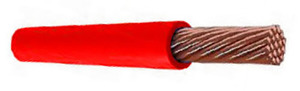
When working with electrical wiring, the maximum danger is represented by the wires to which the phase is connected. Contact with the phase can be fatal, therefore the brightest warning colors, for example, red, have been chosen for these electrical wires.
In addition, if the wires are marked in different colors, then when repairing a particular part, you can quickly determine which of the bundle of wires you need to check first, and which of them are the most dangerous.
Most often, the following colors are used for phase wires:
- Red;
- The black;
- Brown;
- Orange;
- Lilac,
- Pink;
- Purple;
- White;
- The gray ones.
It is in these colors that phase wires can be painted. You can more easily deal with them if you exclude the neutral wire and ground. For convenience, in the diagram, the image of the phase wire is usually denoted by the Latin letter L. If there is more than one phase, but several, a numerical designation should be added to the letter, which looks like this: L1, L2 and L3, for three-phase in 380 V networks. In some versions, the first phase (mass) can be designated by the letter A, the second by B, and already the third by C.
What color is the ground wire
In accordance with current standards, the earth conductor should be yellow-green. It looks like a yellow insulation, which has two longitudinal bright green stripes. But sometimes there is also a color of transverse green-yellow stripes.
Sometimes, the cable may only have bright green or yellow conductors. In this case, "earth" will be indicated by this color. It will also be displayed in the corresponding colors on the diagrams. Most often, engineers draw from bright green, but sometimes yellow conductors can be seen. Designate on the diagrams or devices "ground" in Latin (in English) letters PE. Accordingly, the contacts are marked, where the "earth" wire must be connected.
Sometimes experts call the grounding wire "zero and protective", but not to be confused. If you see such a designation, then know that this is precisely the earth wire, and it is called protective because it reduces the risk of electric shock.
Zero or neutral wire has the following marking color:
- Blue;
- Blue;
- Blue with white stripes.
No colors in electrics are used to mark the neutral wire. So you will find it in any, be it three-core, five-core, and maybe with more large quantity conductors. Blue and its shades usually paint "zero" on different schemes... Professionals call it a working zero, because (which cannot be said about grounding), it is involved in wiring with power. Some, when reading the diagram, call it a minus, while everyone considers the phase "plus".
How to check the wire connection by color
Wire colors in electricity are designed to speed up the identification of conductors. However, relying only on color is dangerous, because any newbie, or an irresponsible worker from the ZhZK-a, could connect them incorrectly. In this regard, before starting work, you must make sure that they are correctly labeled or connected.
In order to check the wires for polarity, we take an indicator screwdriver or a multimeter. It is worth noting that it is much easier to work with a screwdriver: when you touch the phase, the LED built into the case lights up.
If the cable is two-core, then there are practically no problems - you have excluded the phase, then the second conductor that remains is zero. However, three-core wires are also common. Here, to determine you need a tester, or a multimeter. With their help, it is also not difficult to determine which wires are phase (positive) and which ones are zero.
This is done as follows:
- A switch is set on the device in such a way as to select a jackal over 220 V.
- Then you need to pick up two probes, and holding them by the plastic handles, very gently touch the rod of one of the probes to the found wire-phase, and lean the other against the assumed zero.
- After that, the screen should display 220 V, or the voltage that is in fact in the network. Today it may be lower.
![]()
If the display shows a value of 220 V or something in this limit, then the other wire is zero, and the remaining one is presumably "ground". In case the value that appears on the display is less, it is worth continuing the test. With one probe, we again touch the phase, the other with the supposed grounding. If the readings of the device are lower than in the case of the first measurement, then in front of you is the "ground". It should be green or yellow by standards. If suddenly the readings turned out higher, it means that somewhere they messed up, and in front of you is a "zero" wire. The way out of this situation will be either to look for where exactly the wires were connected incorrectly, or leaving everything as it is, remembering that the wires are mixed up.
Wire designations in electrical circuits: connection features
Starting any electro assembly work on lines where the network has already been laid, you must make sure that the wires are connected correctly. This is done using special testing devices.
It must be remembered that when checking the "phase-zero" connection, the readings of the indicator multimeter will always be higher than in the case of a continuity of the "phase-ground" pair.
Wires in electrical circuits are color-coded according to standards. This fact allows the electrician to find zero, grounding and phase in a short period of time. If these wires are connected incorrectly to each other, a short circuit will occur. Sometimes such an oversight leads to the fact that a person receives an electric shock. Therefore, you cannot neglect the rules (PUE) of connection, and you need to know that special color coding of wires is designed to ensure safety when working with electrical wiring. In addition, this systematization significantly reduces the working time of an electrician, since he has the ability to quickly find the contacts he needs.
Features of working with electric wires of different colors:
- If you need to install a new one, or replace an old outlet, it is not necessary to determine the phase at all. The plug doesn't really care which side you plug it in.
- In the case when you connect a switch from a chandelier, you need to know that it is necessary to supply it with a specific phase, and only zero to the bulbs.
- If the color of the contacts of both the phase and zero is exactly the same, then the value of the conductors is determined using an indicator screwdriver, where the handle is made of transparent plastic with a diode inside.
- Before determining the conductor, the electrical circuit in the house or other room must be de-energized, and the wiring at the ends must be cleaned and spread apart. If this is not done, then they can accidentally touch and get a short circuit.
The use of color coding in electrics has made life much easier for people. In addition, thanks to color coding, safety when working with live wires has been raised to a high level.
Designations and colors of wires in electrics (video)
Those who work with electrical wiring, whether they are qualified craftsmen or novice electricians, should be careful during the installation of an electrical wire and know which wire is designated as. When laying wiring and connecting contacts, always connect the conductors according to the color coding according to the new rules, and for the sake of your safety and respect for those who will work with them in the future, do not confuse them. Remember that your oversight can lead to negative disastrous consequences.
Today it is difficult to imagine electrical wiring without the use of colored insulation. And these are not marketing "chips" of manufacturers seeking to present their products in colors, and unfashionable innovations that consumers are striving for. In fact, this is a simple and practical necessity, which is determined by strict state standards for compliance with the correct labeling. What is it for.
Wire colors in electrical connections
Color marking
All the variety of colors and certain colors selected from this palette are reduced to one (single) standard (PUE). Thus, wire strands are identified by color or letter and number designations. The adoption of a single standard for color identification of electrical wires greatly facilitated the work associated with their switching. Each vein has a specific purpose and is indicated by an appropriate tone (blue, yellow, green, gray, etc.).
Wire color marking is done along their entire length. Additionally, identification is carried out at the connection points and at the ends of the cores. To do this, use colored electrical tape or heat shrink tubes (cambric) of the appropriate tones.
Let's look at how the wiring and color coding of wires for three-phase, single-phase and networks is performed direct current.
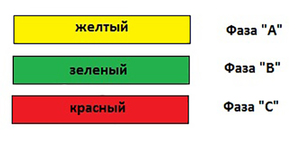
Color marking of wires and busbars of alternating three-phase current
Coloring of buses and high-voltage bushings of transformers in three-phase networks is done as follows:
- tires with phase "A" are painted with a yellow palette;
- tires with phase "B" - green;
- tires with phase "C" - in red tone.
Wire color marking. Electrical wire colors (DC busbars)
In the national economy, direct current circuits are often used. They find their application in certain areas:
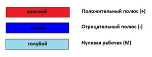
In DC networks, there is no phase and zero contact. For such networks, only two contacts of different polarities are used - plus and minus. To distinguish them, respectively, two colors are used. The positive charge turns red and the negative one turns blue. The middle contact is marked in blue, which is marked with the letter "M".
 Old-timers of electrical wiring are probably familiar with the old methods of wiring and color coding of electrical wires. The main colors of the electric cable were white and black. But this time has gone into the distant past. Each color now, and there are clearly not two of them, has its own purpose and dominant profile.
Contact colors in electrics indicate the purpose and belonging of conductors to a certain group, which facilitates their switching. The chance of error during installation, which could lead to a short circuit during test connection or electric shock during repairs, is greatly reduced.
Wire color marking. Color palette of protective zero and working contact
Zero working contact is indicated by blue tone and the letter N. The PE marking denotes a zero protective contact, which is painted in yellow-green stripes. A combination of these tones is used when marking pinched conductors.
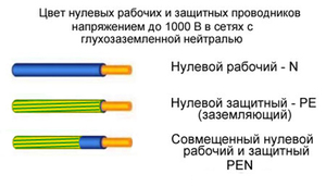 Conductor of blue color along the entire length with yellow-green stripes at the connection points, it indicates a combined zero working and zero protective connection (PEN). However, GOST also admits the inverse opposite of this color:
- Working zero contact denoted by the letter N and has a blue color.
- Protective zero (PE) with yellow-green color.
- Combined (PEN) is identified by a yellow-green color and a blue mark at the ends.
Single-phase electrical circuit. Coloring phase wires
According to the PUE standards, phase contacts are usually indicated in black, red, purple, white, orange or turquoise.
Single-phase electrical circuits are created by branching off a three-phase electrical network. In this case, the color of the phase contact of the single-phase circuit must match the color of the phase wire of the three-phase connection. In this case, the color marking of the phase contacts should not coincide with the N - PE - PEN colors. On unmarked cables, color marks are placed at the connection. To designate them, use colored electrical tape or heat shrink tubing (cambric).
What color is the ground wire. Wire color marking (phase - zero - ground)
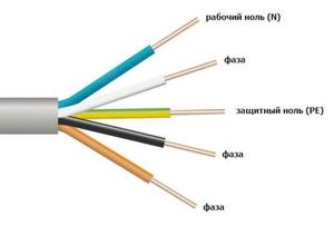
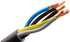
 When installing lighting networks and supplying power to sockets, a cable with three wires (three-core cable) is used. The use of a standard color system (phase-zero-ground wire color) significantly reduces repair time. Multi-conductor wiring in standard colored insulation greatly simplifies the wiring of electrical circuits and installation work on the wiring of AC networks with its ground. This is especially true when wiring and repairing the electrical system, which is done by different craftsmen, but under the general guidance of GOST. Otherwise, each master would have to double-check the work of his predecessor.
“Ground” is usually indicated by a yellow-green color and PE marking. Sometimes there is a green-yellow color and marking "P E N". In this case, there is a blue braid at the ends of the electric wire at the attachment points and the grounding is aligned with the neutral.
The distribution board is connected to the grounding bus and to the metal door of the board. The junction box is usually connected to the grounded wires of the fixtures or the grounding pins of the socket.
Wire color marking. Zero and neutral designation
 Zero is indicated in blue. In the switchboard, it is connected to the zero bus and is designated by the letter N. All blue wires are also connected to the bus. It is connected to the outlet using a meter or directly, without installing an automatic device.
The distribution box wires (except for the wire from the switch) are indicated by a blue neutral palette. When connected, they do not take part in the switching process. "Neutral" blue wires are connected to the sockets and pin N, which is marked on the back of the socket.
Wire color marking. Phase color coding
 The phase wire is usually indicated in red or black. Although its colors may not be so unambiguous. It can also be brown, but never blue, green and yellow. In automatic shields, the "phase" coming from the consumer's load is connected to the bottom contact of the meter. The phase conductor is switched in the switches. In this case, the contact closes during shutdown and voltage is supplied to consumers. The black wire of the phase socket is connected to the contact, which is designated by the letter L.
Alphanumeric designation of wires by color
Knowledge of elementary wire color markings and their purpose will help any amateur electrician in the installation of household electrical wiring (with grounding). If you wish, you can easily make it according to the required standards in compliance with all technical standards.
Electric cables produced during the USSR period were mostly black or white insulation, which created difficulties and inconveniences during electrical work, because it was not always possible to quickly identify the purpose of a particular wire. Now on the shelves there are cables of various colors. This diversity has a very specific purpose. The color coding of each type of wire (zero, minus, plus, grounding and various phases) is primarily intended to make electrical work safer, and finding and connecting contacts is simpler and faster.
In order to avoid discrepancies in the color scheme, depending on which manufacturer made these products, it is strictly standardized in the PUE (electrical installation rules) and state standards... Until 2009, GOST R 50462-92 was used, in which it replaced GOST R 50462-2009, changes were made regarding the colors of wires in three-phase networks, colors of plus, minus and zero in DC networks, brown is recommended as the main shade for the phase in a single-phase network, the use of a combination of yellow and green for grounding is approved.
Various types of cables are:
- Black
- Brown
- Red
- Orange
- Yellow
- Green
- Blue
- Purple
- Gray
- White
- Pink
- Turquoise
The cable is marked with the desired color at the ends (in other words, in the area of \u200b\u200bthe connections), as well as along the entire length in the form of solid color insulation or individual marks.
Coloring of cables of different types
Three-phase networks
In a three-phase network of transformer substations with alternating current, according to GOST 1992, phase A has a yellow wire, B is a green wire, C is red. According to the new GOST, it is preferable to use brown for phase A, black for phase B and gray for phase C. In ordinary household cables, white is used for phase A, black for phase B, and red for C.
The ground wire is usually colored in the form of yellow-green stripes in the longitudinal or transverse direction. Moreover, each color cannot occupy less than 30% and more than 70% of the surface. Less commonly, the marking of the grounding cable can be only yellow or only green. If such a cable is laid in an open way, then it is permissible to use black color, as it improves corrosion protection. Also, black was used in the designation of the ground wire everywhere before the amendments to the regulatory documentation in 2009.
Zero has blue or blue wire insulation. 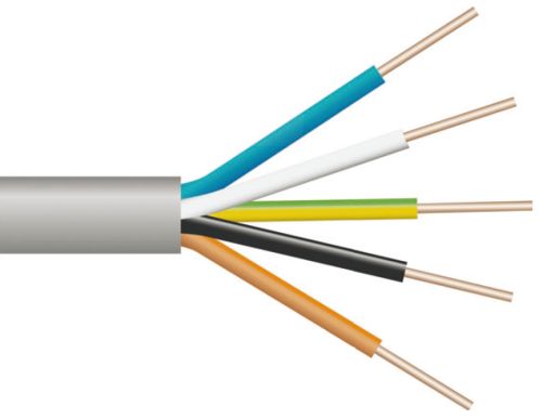
Single-phase networks
In this type of AC networks, the phase insulation is most often brown, gray or black, but the use of red, purple, pink, white and turquoise shades is also allowed. At the same time, in a single-phase network powered by a single-phase power source, wires with brown insulation are usually used. If a single-phase conductor is performed as a branch of a three-phase electrical circuit, then it is marked with the color that marked the phase of the three-phase circuit.
The ground wires are similar to the previous case, marked with a combination of yellow and green.
PEN conductors in which a protective zero and a working zero are connected along the entire length are colored blue, and at the ends are yellow-green marked. At the same time, GOST permits another option - yellow-green lines along the entire length of the wire and blue marks at the ends. 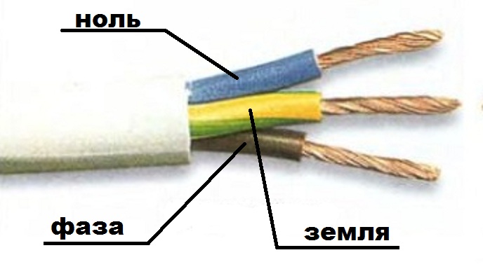
DC networks
If a DC system was commissioned before 2009, then zero should be light blue, plus - red, negative pole - dark blue. According to the new GOST, brown should be used for plus, gray for minus, and blue for zero.
Labeling rules
Marking is done at the ends of the wires, i.e. in the places of their connection with each other or with various equipment.
It is allowed to combine the colors allowed for marking, but, if possible, avoiding confusion. So, yellow and green can only be used in combination with each other and only for grounding, and not, for example, plus / minus.
If the wires in the system are initially marked incorrectly or not at all, then this can be corrected:
- By applying letter, symbol or color marking with indelible markers (it is convenient if the wire is white or at least light)
- Sticker of polyurethane tags with inscriptions
- Using heat shrink tubing or electrical tape of the desired color
Naturally, you need to first determine which wire is a plus, which is a minus, etc. the purpose of each wire (in household electrical network this can be done with an indicator screwdriver or a multimeter).
It is not always possible to create a colored circuit diagram in a paper version. Then, in black and white copies, letter designations are used to uniquely identify the color of each type of wire. Them full list is given in GOST R 50462-2009. For marking cables that include several wires of different types in the letter designations, different colors are separated by a plus sign.
Conclusion
Color coding of wires, depending on the purpose of each of them, allows you to make electrical work more convenient, reduces the likelihood of errors and emergencies. Therefore, it is necessary to comply with it even for the system of individual power supply of an apartment or house, not to mention larger industrial, commercial, public and other facilities.


