Page 4
The authors studied the conditions for the formation of a gas cushion under the sectioning grid and the effect of the open section of the redistribution grids on the uniformity of fluidization.
To reduce the loss with a failure with a large amount of fines in peat, a decrease in the open section of the grate and a corresponding increase in the blast pressure are required.
Consideration of the data table. 5 shows that the depth of destruction is practically independent of the open section of the lattice, however, the degree of saturation with hydrogen in this case increases, which makes it possible to increase the yield of diesel fuel with a given iodine number.
The sum of the hole areas in grate for the passage of air to the fuel layer is called the open section of the grate. In grates intended for burning lumpy fuel, the free area is 25 - 30% of the grate area.
The ratio of the total area of \u200b\u200bair slots or holes in the lattice to its other area is called the open section of the lattice. There are gratings with a small (5 - 15%) and large (15 - 40%) free cross section. The required free area is determined by the properties of the fuel being burned.
With a decrease in the number of holes in the lattice from 223 to 61 with the same open area of \u200b\u200bthe lattice, the height of the pad remains practically constant. It also does not change with an increase in the height of the fixed layer on the redistribution grid from 270 to 350 mm.
Losses with a dip Q p refer to grate grates and depend mainly on the design and the free section of the grate.
The gas velocity in the section of the apparatus is usually taken in the range of 1 - 3 m / s, and the open section of the grating is chosen so that the gas velocity in the holes is 6 - 13 m / s. A decrease in speed leads to a violation of the integrity of the foam layer, an increase in speed above these limits dramatically increases losses due to splashing.
The hole diameter of the upper grating is 3 mm, the distance between the holes and their number are determined based on the provision of a free section of the grating within 5 - 7% of its total area. Thus, the air velocity in the grill openings is approx.
| Spray booth with bottom suction and top air supply | Diagram of the VTSNIIOT dust bin for sharpening machines - bunker of the first cleaning stage. 3 - suction branch pipe. 4 - fixed flap. 5 - adjustable flap. |
The product is installed at such a height above the grate so that the air flow rate is no more than the speed of its movement in the living section of the grate. Supply air is supplied from above evenly over the entire area of \u200b\u200bthe chamber ceiling. A false ceiling fitted with filter cassettes should be used.
The ratio of the area of \u200b\u200ball gaps R in the grate through which air enters the layer to the entire area of \u200b\u200bthe grate is called the free section of the grate and is usually expressed as a percentage. The required size of the open section of the grate depends on the type of fuel burned and the size of the pieces. So, when burning sod peat and firewood, beam grates are used.
, page 4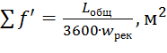 (19)
(19)
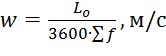
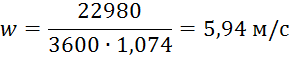
According to the manufacturer's catalog, we accept three external grilles for installation AVR with protective mesh 750x1000, white - RAL9016: ARN + S 750 x 1000, with a free area \u003d 0.358 m 2. The total free area of \u200b\u200bthe three grids \u003d 1.074 m 2.
Air speed in the total free area of \u200b\u200bthree gratings
 (20)
(20)
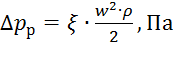
Aerodynamic resistance when air passes through the grilles
 (21)
(21)
where is the coefficient of local resistance of the lattice, taken according to the manufacturer's data, \u003d 2.36

The dimensions of the free cross-section of the air intake shaft are taken based on the requirements (Appendix 19) to the maximum permissible air velocity in it.
Let us find the area of \u200b\u200bthe open section of the mine, based on the permissible air velocity in it and the geometric dimensions of the gratings. The value is taken similarly to (19).
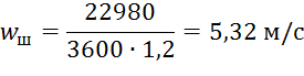
We accept the size of the mine (by internal measurement) 1.0x1.2 m... Free area of \u200b\u200bthe mine
Air velocity in the open section of the mine
Dynamic pressure when air moves through the mine

CCM lattices
The view of the air intake shaft is presented in the graphic part of the project.
3.2. Selection of air valve KVU
The method for calculating the CVC is similar to the calculation of the air intake grille.
The approximate area of \u200b\u200bthe free cross-section is taken similarly to (18) ![]()
By technical specifications we accept the valve from the manufacturer's website KVU 1600x1000, with a free area \u003d 1.48 m 2.

Adopted similarly to the resistance of the throttle valve at an angle of rotation of the blades of 15⁰.
3.3. Aerodynamic calculation of an unbranched duct
The task of aerodynamic calculation of an unbranched air duct is to identify the angle of installation of an adjustable device in each inlet opening, which ensures the outflow of a given air flow rate into the room. At the same time, it is determined: pressure loss in the air distributor and the maximum aerodynamic resistance of the air duct and the ventilation network as a whole.
When installing a multi-leaf flow regulator on a branch (grille ADN-K), outside the main air duct, the influence of the position of the flow control blades on the pressure loss in the transit flow is practically excluded. For the calculation of air ducts, there are aerodynamic characteristics that take into account the position (angle of installation) of the regulator blades: flow rate, direction, and shape of the jet.
The air duct is divided into separate sections with a constant air flow along the length. The sections are numbered from the end of the duct. Since the flow regulator is not installed in the end grille (the grille is installed ADN-K 400x800), the pressure in front of the second (or each subsequent) lattice is known. Taking this into account, the calculated pressure losses are determined to find the angle of rotation (position) of the flow regulator by the aerodynamic characteristic.
3.3.1. Method for calculating an unbranched duct P1
Initial data
- 22980 m 3 / h;
- 3830 m 3 / h;
- 3.58 m / s;
The distance between the gratings is 2.93 m;
Inclination angle of the supply incomplete fan jet - 27⁰;
We determine the dimensions of the initial section of the duct of the end section 1-2 (see the graphic part), trying to keep its height constant.
To create a truly effective ventilation system, a lot of problems must be solved, one of which is competent air distribution. Without focusing on this aspect when designing ventilation and air conditioning systems, as a result, you can get increased noise, drafts, the presence of stagnant zones even in ventilation systems with high efficiency characteristics. The most important device influencing the correct distribution of air flows in the room is the air distributor. Depending on the installation and design features, these devices are called grilles or diffusers.
Air terminal classification
All air diffusers are classified:
- By appointment. They can be supply, exhaust and overflow.
- By the degree of impact on air masses. These devices can be mixing and displacement.
- Installation. Air diffusers can be used for indoor or outdoor installation.
Internal diffusers are classified as ceiling, floor or wall.
Supply air, in turn, are classified according to the shape of the outgoing air stream, which can be:
- Vertical compact air jets.
- Conical jets.
- Complete and incomplete fan-shaped air currents.
In this post, we will look at the most common diffusers: ceiling, slot, nozzle and low velocity.
Requirements for modern air distributors
For many, ventilation is synonymous with constant background noise. The consequences of this chronic fatigue, irritability and headache. Based on this, the air distributor should be quiet.
In addition, it is not entirely pleasant to be in a room if you constantly feel chilled air currents on yourself. This is not only unpleasant, but can also lead to illness, so the second requirement: the diffuser should not create drafts.
Various circumstances often require a change of scenery. You can change furniture or rearrange office equipment. It is also easy to order a new original design of the room, but it is rather difficult to change the air diffusers, which were calculated at the design stage. The third requirement "follows" from this: the air distributor should be unobtrusive, or, as the designers say, "dissolved in the interior of the room."
Slotted air flow distributors
Slot diffusers are ventilation equipment designed to supply fresh air and extract exhaust air from rooms with high requirements for design and air quality. For optimal air distribution, ceiling heights when using this equipment are limited to 4 meters.
The design of the device consists of an aluminum body with horizontal slotted holes, the number of which, depending on the model, can vary from 1 to 6. A cylindrical roller is mounted inside the diffuser to control the direction of air flow. Typically, these diffusers are equipped with a plenum box to control the air flow.
The slot height can also be different: from 8 to 25 mm. The length of the device is not regulated and can be from 2 cm to 3 m, so that they can be mounted in continuous lines of almost any shape. Linear slot diffusers are characterized by good aerodynamic properties, attractive design and a high degree of induction, due to which the supply air flows quickly heat up. Such devices are mounted in suspended ceilings and wall structures. The mounting height must not be less than 2.6 m.
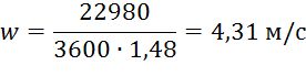
Ceiling diffusers
 Ceiling air diffusers can be supply or extract air. These devices differ in: design, shape, size, performance, air jet formation. In addition, diffusers differ in aerodynamic characteristics, air flow distribution, and the material from which they are made.
- The design of these devices consists of a decorative grille, behind which are attached the impeller (if the diffuser is supply) and the static pressure chamber. The adjustable "shades" have elements that direct the air flow.
- The form. Most ceiling diffusers are round or square. But we should not forget that slotted air distributors are also considered ceiling ones, and they have a rectangular shape.
- Sizes of round air distributors vary from 10 cm to 60 cm. For square ones - from 15x15 cm to 90x90 cm.
- Installation method. Installed in a false ceiling, cut into a plasterboard panel or mounted in stretch ceiling with additional rings.
- Ceiling diffusers produce fan, turbulent, vortex, conical and nozzle air flows.
- The air distribution in these devices can vary on different sides (in square supply units) or be circular.
Most often, these devices are used in residential and office premises, shops, as well as restaurants and catering places.
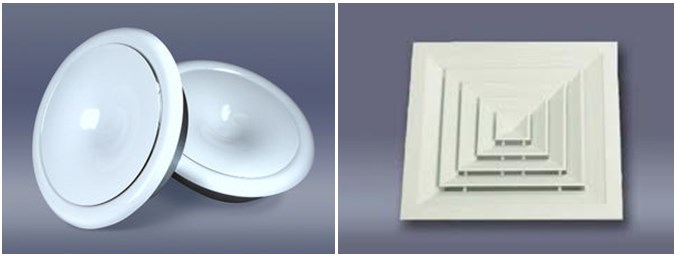
Nozzle diffusers
 Nozzle air distributors are used to supply clean air streams over long distances. To increase the range of the air flow, the nozzle distributors are combined into blocks that can have different shape and be made of various materials.
By design, nozzle diffusers can have movable and fixed nozzles, which have an optimal profile that provides low aerodynamic resistance and low noise level. This type of air distributor is surface mounted using glue, self-tapping screws or rivets, and some models can be installed directly into a circular duct.
These devices are made of anodized aluminum, which allows them to be used to distribute heated air and high humidity air masses. Such devices are used in ventilation systems of industrial enterprises, commercial buildings, parking lots, etc.
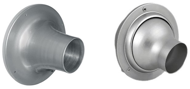
Low velocity diffusers
 Low-speed air distributors work on the principle of displacement of polluted air from the served room. They are designed to supply clean air directly to the service area, with a low air flow rate and a small temperature difference between the inflow and the room air mixture. These devices differ in installation method, shape, size and design.
There are several types of low velocity air distributors:
- Wall mounted.
- Outdoor.
- Embedded.
Floor and wall mounted low velocity diffusers are designed for small, medium and large airflow rates. Most often they are installed under the seats in cinemas, large concert and educational premises, shops, museums, sports facilities. Built-in, floor devices can be installed in staircases and steps.
Low speed attachments are available in powder coated metal or anodized aluminum. The device consists of an outer and inner shell and a housing with a supply pipe. Some valve models can be equipped with rotary nozzles to regulate the direction of the air flow.
Diffuser calculation
Calculation of air diffusers is a rather complicated but necessary process, which consists in choosing a device that meets the following requirements:
- The outlet air flow rate should be optimal.
- Air flow temperature difference at the inlet working area should be minimal.
Calculation algorithm
- Initially, the calculation of the supply of air mixture for a room of a certain size and architectural shape, with a given productivity L p (m3 / h) and a temperature difference of the supply air Δt 0 (° С); device mounting height h (m) and other air distribution characteristics.
- According to the permissible parameters of the speed of movement of air masses Ud (m / s) and the temperature difference between the supply air and the air at the entrance to the working area, the speed and amount of air supplied from one diffuser is determined.
- After that, the required location and the number of devices required for optimal air distribution in a particular room are calculated.
Advice:
If you do not have special engineering knowledge, then for the correct calculation of air diffusers, contact organizations specializing in this type of activity. If you decide to do the calculations yourself, then use specialized software.