The time has long passed when the presence of protective grounding was the prerogative of exclusively industrial enterprises. With the growing number of household appliances in our home, protective grounding has become an indispensable attribute of any private home. And this is not surprising. Any violation in the insulation of electrical appliances can lead to very serious consequences for the inhabitants of the house.
The best way to protect yourself is to equip grounding. There is no need to involve professionals in the device of the ground loop at home. Anyone can do this task. The main thing is patience and attentiveness during work.
Purpose and arrangement of the ground loop
Protective grounding is a connection between the current-carrying parts of electrical installations and the ground, made intentionally.
During normal operation of electrical appliances, their case is not energized. It is safe to work with such devices. Unfortunately, the more devices, the higher the probability of failure of any of them. The slightest damage to the insulating layer - and the body of the device will be energized. Touching such a device is deadly.
It is these situations that prevent protective grounding. Everyone knows that electric current flows in the direction of least resistance. The presence of a ground loop in a private house with a low resistance value is a guarantee that the current will go to the ground.
The most common variant of the ground loop is electrodes buried in the ground. They are interconnected in the form of a closed contour of a certain shape. A triangular shape is often used. It is possible to perform a ground loop along the perimeter of the building. Among the main criteria for choosing the shape of the contour, the convenience of its installation and the size of the territory used for its construction are distinguished. The ground loop is connected to the electrical panel using a special ground cable.
The optimal distance between the house and the ground loop is 5 m. At the same time, a distance closer than 1 m and further than 10 m is considered unacceptable.
Tip: the minimum depth of the ground loop is 0.8 m. The loop, located within the boundaries of soil freezing, does not work in winter.
The electrodes are buried in the soil by 1.5 - 3 m. The choice of depth for each individual case depends on the structure of the soil and its moisture content. The more the soil is saturated with water, the less the electrodes are buried.
Materials required for the installation of the ground loop
As a rule, the ground loop is made from improvised materials. Any ferrous metal rod can serve as a ground electrode. The choice is very wide. The main criterion is convenience when driving into the ground. Mostly used steel corners. It is possible to use fittings of a smooth structure, pipes, I-beams. The only requirement is a metal cross section of 1.5 cm 2.
To determine the number of required electrodes, calculations are used extremely rarely. Basically use the experimental way. The most common number of electrodes is three. Thus, a triangular ground loop is obtained. The vertices of the triangle are the electrodes. The distance between adjacent electrodes less than 1.2 m is unacceptable. It is calculated based on the resistance of the soil. The electrodes are connected to each other using metal strips. A similar strip also serves to connect the circuit to the distribution one. 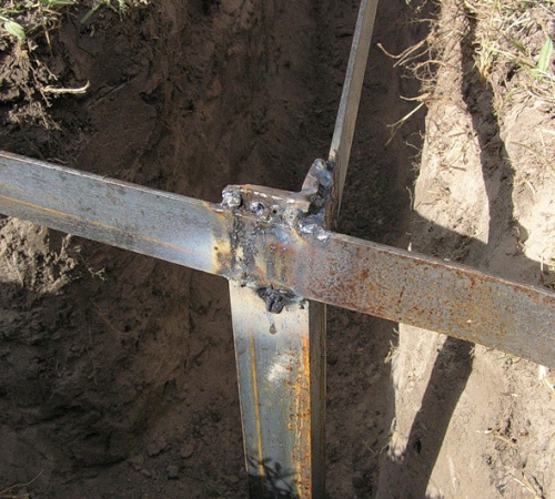
Be sure to consult a qualified electrician residing in the same area before installing a ground loop. Such a specialist knows from experience how to make a ground loop that is ideal for a given area:
- what should be the distance from the building to the contour;
- what should be the distance between adjacent electrodes;
- the number of required electrodes;
- the depth to which the electrodes should be hammered;
- the depth at which the contour should be placed.
The undeniable advantage of a homemade grounding system is its low price.
It is not necessary to make a ground loop only from improvised materials. Special ready-made grounding systems appeared on sale.
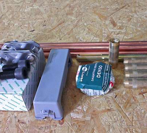
The Modular Grounding System Kit consists of the following:
- rods made of high quality steel and plated with copper. The length of the rods is about 1.5 m, the diameter is 0.14 m. Each rod is equipped with a copper-plated thread;
- brass couplings for connecting the elements of the ground loop;
- tips. Contribute to facilitating the driving of the rod into the ground. Attached to the rod with a thread. There are several types of tips. Designed for various types of soil;
- clamps for connecting horizontal elements to vertical ones;
- anti-corrosion paste for the treatment of all elements of the earthing system.
Advantages of modular grounding systems:
- Rods made of stainless steel and coated with copper are less prone to corrosion.
- There is no need for welding work.
- There is no need for special equipment during installation.
- Space saving. For the equipment of the entire system, 1 m 2 is enough.
- Durability.
Grounding calculation
Whichever version of the grounding system is chosen, a mandatory step is preliminary calculations of the grounding parameters. Usually grounding is performed empirically. This method will help to avoid many complex calculations.
The algorithm for mounting the ground loop in this case is as follows:
- We build a triangular ground loop at a distance of 5 m from the house. We take the length of the electrodes 3 m, the distance between them is 2 m. We use metal rods.
- We connect the electrodes to each other.
- We measure the resistance of the ground loop. To measure resistance, we use a special device - an ohmmeter. The maximum allowable ground loop resistance is 10 ohms. The optimal value is 4 ohms. We compare the obtained result with the optimal value.

- If the obtained resistance value does not correspond to the optimal one, we add one more electrode to the circuit.
- We connect all the electrodes in a new circuit.
- We again measure the resistance of the circuit.
- We repeat the above procedures until we achieve a loop resistance value of 4 ohms.
It is possible to determine the number of required electrodes and the length of the horizontal earth electrode using calculations:
- If there is a homogeneous soil on the site, we determine the resistance of one electrode using formula 1:
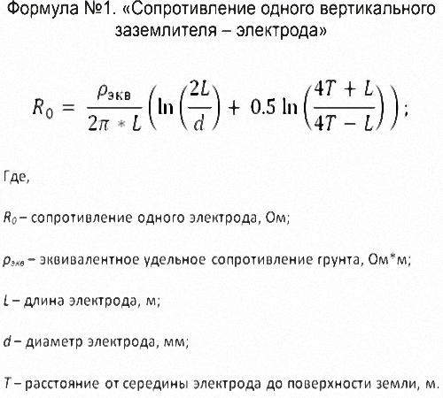
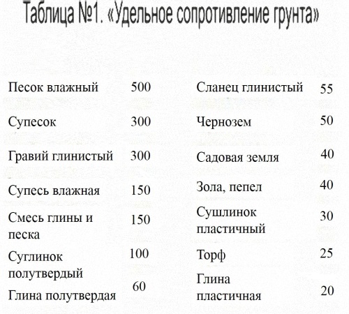
Use Table 1 to determine the soil resistivity value.
If there is an inhomogeneous soil on the site, we determine the resistance of one electrode according to formula 2:
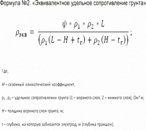
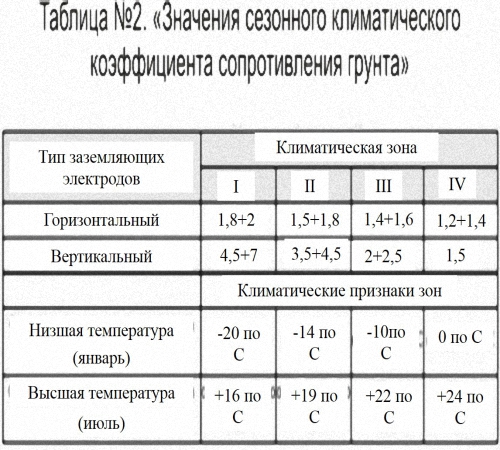
At the same time, the values of the seasonal climatic coefficient are given in Table 2:
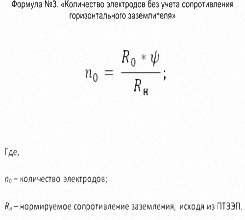
According to formula 3, we determine the required number of electrodes without taking into account the resistance of the horizontal ground electrode:
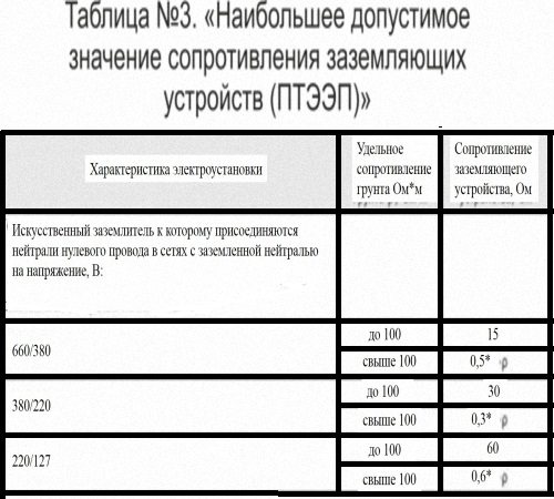
To determine the normalized grounding resistance, we use table 3:
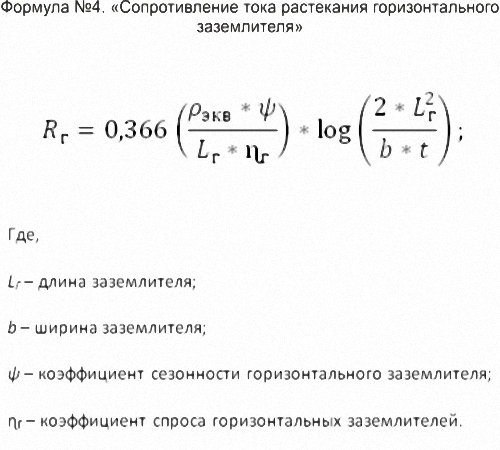
Let's determine the resistance of the horizontal ground electrode according to formula 4:
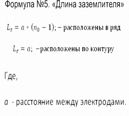
In this case, to determine the length of the ground electrode, we use formula 5:
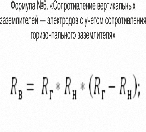
Calculate the resistance of the electrodes, taking into account the resistance of the horizontal ground electrode according to formula 6:
Let's determine the final number of electrodes required for the device of the ground loop:
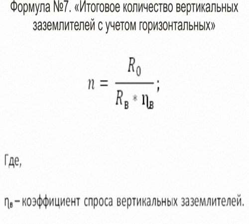
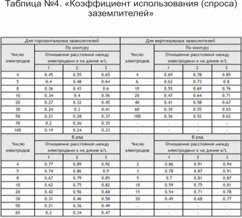
To determine the demand factor for vertical grounding, we will use Table 4:
The final value of the number of electrodes, obtained as a result of the above calculations, is rounded up to a higher integer. Which method to use - experienced or calculated - is a personal matter for everyone. Choose any, based on your own preferences.
How to make a ground loop with your own hands
After carrying out all the preliminary calculations and preparing the necessary materials, we proceed directly to the installation of the ground loop.
Tip: the best time to install a ground loop is summer. And not only due to the fact that in the warm season it is easier to carry out earthworks. The fact is that in dry soil the resistance is greater. Having achieved the optimal resistance value in dry weather, you should not worry about the deterioration of this indicator in the future. On the contrary, with increasing soil moisture, the resistance will decrease.
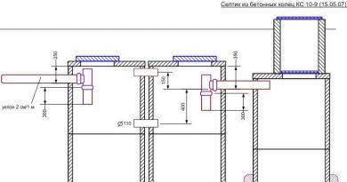
Consider the main stages of installation of a triangular ground loop, the diagram of which is shown in the figure.
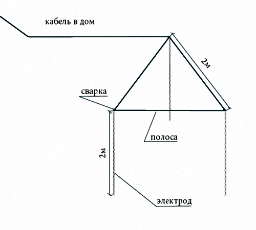
- At a distance of about 5 m from the house in a convenient place, dig a trench in the form of an equilateral triangle. The depth of the trench is about 1 m, the width is 0.5 m. The length of the side of the triangle must correspond to the calculations made earlier. From any corner to the switchboard of the house, dig a trench.

- Drive electrodes into each of the vertices of the triangle. Pre-sharpen the ends of the electrodes with a grinder.
- For very hard ground, pre-drill holes for the electrodes. After inserting the electrode into the well, fill it with a mixture of soil and salt.
- Do not immerse the electrode in the ground completely, leave the tip above the ground.
- Connect the electrodes together with a steel strip, at least 40 wide and at least 5 mm thick. Use welding to fasten the electrodes and the strip.
- Connect one of the electrodes to the switchboard by laying an identical steel strip in the previously prepared trench.
- Connect the strip and switchboard with a 10mm bolt. Be sure to weld the bolt to the shield.
- The next step is to measure the ground loop. Use an ohmmeter to measure.
- If the measurement result corresponds to the optimal resistance value, the ground loop is installed correctly. You can start digging trenches.
- If, when measuring the ground loop, it turns out that the resistance exceeds the standard value, add another electrode.
- For digging a trench, use only homogeneous soil. The presence of impurities of crushed stone and construction debris is unacceptable.
- The ground loop is ready.