All drawings must be made in accordance with ESKD standards, be distinguished by a clear and accurate execution.
Formats
Control work drawings are made on sheets of standard sizes. Standard sizes of sheet formats are defined by GOST 2.301-68. The dimensions of the formats along the outer frame are shown in Table 1.
Sizes of formats according to GOST 2.301–68 Table 1
|
Designation |
Dimensions of the sides of the format, mm |
Control tasks should be performed on A4 and A3 format.
In accordance with GOST 2.301-68, the drawing has a frame at a distance of 20 mm from the left border of the format, and at a distance of 5 mm from the other three sides (Fig. 1). The outer frame of the format is drawn with a solid thin line, the inner frame is applied with a solid main line.
The field on the left side is intended for filing and stitching drawings into an album.
The drawing is accompanied by the main inscription in accordance with GOST 2.104–68. On an A4 sheet, the main inscription is placed only along the short side
Rice. 1. The location of the title block on the sheet
Main inscription
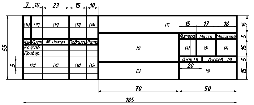
Fig.2.a. Form of the title block

Fig.2.b. Sample filling in the main inscription UCH
|
Font size, mm |
||
|
Drawing name |
||
|
Document designation according to GOST 2.201-80 |
||
|
Product material designation |
||
|
Drawing letter "y" training drawing |
||
|
Product weight |
||
|
Sheet serial number |
||
|
Total number of sheets |
||
|
The name of the educational institution and the code of the group |
||
|
The nature of the work performed by the person signing the document |
||
|
Surnames of the persons who signed the document |
||
|
Signatures of persons whose names are indicated in column 11 |
||
|
Date of signing the document |
||
|
Change table columns |
Column 2: IG - discipline code,
851 - group number,
002 – variant number,
001 is the drawing number.
Column 9 VGKS - the name of the educational institution,
ТЭ851 - 22 - group number and student code.
Scales
When making drawings, image scales are used, which are selected from the following row according to GOST 2.302–68:
scale reduction: 1:2; 1:2.5; 1:4; 1:5; 1:10; 1:15; 1:20; 1:25; 1:40; 1:50; 1:75; 1:100; 1:200; 1:400; 1:500; 1:800; 1:1000;
magnification ratio: 2:1; 2.5:1; 4:1; 5:1; 10:1; 20:1; 40:1; 50:1; 100:1.
The preferred scale for instructional drawings is 1:1 (life size image).
In the main inscription in column 6, the scale is entered in the form of 1:1 or 2:1. In the drawings, it should be designated as M 1:1 or M 2:1, etc.
lines
The thickness of the lines must strictly comply with GOST 2.303-68. The name, style, thickness of lines in relation to the thickness of the main line and their main purposes are given in Table 3.
Drawing lines Table 3

Plan of work on the drawing:
The application of the main images in order to evenly fill the drawing field, while all the lines are made thin so that it is easy to remove them.
Then draw axes of symmetry, center lines.
Draw contour lines and draw individual elements of the image (grooves, holes, etc.).
The stroke of the drawing is carried out with a wide front.
extra lines that are not subject to stroke are deleted.
Using lines in AutoCAD:
1 - solid main thick (contour) - 0.60 mm;
2 - main thin - 0.20 mm;
3 - axial (dash-dotted thin) - 0.25 mm;
4 - dashed (invisible contour) - 0.3 mm;
5 - dash-dot thin with two points (fold lines on the development) - ACAD ISO 12W100 - 0.25 mm.
Font
All inscriptions on drawings and other technical documents of all industries and construction are performed in a standard font.
GOST 2.304-81 establishes two types of font: type A and type B, with and without slope. Figure 3 shows type B font.
It is recommended to study the design of writing letters in a drawing font not in alphabetical order, but by dividing them into groups according to the uniformity of writing. As a basis, you can take the principle of placing letter elements relative to the auxiliary grid, which is shown in Figure 3 a.
In these guidelines, type B font with an inclination of 75º and the parameters shown in Table 4 is considered in detail.
The font size h defines (height in mm) the capital letters. The height of lowercase letters c (without processes) is determined from the ratio of their height to the font size (for example, c=7/10 h)/. In relation to the height of capital letters, all other font parameters are determined: g - letter width; d – font line thickness (d= 1/10 h); a is the distance between letters; b – minimum row spacing (auxiliary grid height); e is the minimum distance between words.

Fig.3. Font type B with a slope according to GOST 2.304-81

Fig.3.a Construction of type B font on the auxiliary grid
Type B font parameters Table 4

Dimensioning
The size of the depicted product and its elements in the drawings is determined by the dimensions, the total number of which should be minimal, but sufficient for manufacturing and its control. Linear dimensions are indicated in millimeters without designation of units, while in other units the dimension number is accompanied by the designation of this unit. Angular dimensions are indicated on the drawing in degrees, minutes and seconds.
The rules for applying dimensions are established by GOST 2.307–68. Dimensions in the drawings are indicated by dimension lines. Dimension lines are limited by arrows that touch extension lines, contour lines, center lines. The extension line protrudes from the arrow by 1 - 5 mm. The dimension line is drawn parallel to the segment, the size of which is indicated, if possible, outside the contour of the image. The minimum distance between parallel dimension lines is 7 - 10 mm, and between the dimension line and the contour line is 10 mm (they are chosen depending on the size of the image and the saturation of the drawing). Dimension lines should not intersect with extension lines.
Dimensions in the drawings are applied only on visible elements of the product. It is allowed to apply the dimensions of invisible surfaces when these surfaces are not shown visible anywhere in the drawing.
Some examples of dimensioning are shown in Figures 4 (a - h).

a) The shape and size of the arrows

b) Rules for drawing dimension lines

c) Drawing angular dimensions

d) Drawing dimensions on flat drawings

e) Location of dimension lines


e) Chamfer dimensions g) Radius and diameter symbols


h) Cases of breaking the dimension line and applying dimensions with insufficient space
Fig.4a–4h. Rules for applying dimensions according to GOST 2.307–68
It is not allowed to use contour lines, axial, center, extension lines as dimension lines. Each size is listed only once. Dimensional numbers are applied above the dimension line as close as possible to its middle. To indicate the diameter and radius, signs are applied in front of the dimension number (see Fig. 4g). When specifying the size of the angles, the dimension line is drawn in the form of an arc centered at the apex of the corner (see Fig. 4 c).
It is not recommended to apply the size in the shaded area. Dimensional numbers in this case indicate on the horizontal lines-shelves. It is not allowed to break the contour line for drawing a dimension number, other lines are allowed. With parallel dimension lines, dimension numbers are staggered. If there is not enough space for the arrow, the lines near it are interrupted. Dimension lines at different slopes determine the position of dimension numbers. If there are repeating elements, indicate their number. The rules for specifying dimensions in the drawings are extensive, they should be studied in accordance with GOST 2.307–68.
The following document naming structure is proposed:
The entire project is labeled:
DP 02609639-240502-07-05 TP,
Where DP - index, meaning graduation project;
02069639 - code of the university, in this case KSTU;
240502 - specialty code, in particular "Technology of processing plastics and elastomers";
07 - the student's serial number according to the group list;
05 - the last digits of the calendar year;
TP - technical design code.
This designation is recorded in the top line of the stamp of the "Project List" sheet.
The project sheet reflects all the documentation included in the project, an example is shown in fig. 2.14.
Text documentation:
The settlement and explanatory note has the PZ code and is indicated
DP 02609639-240502-07-05 PZ
This designation is placed on the title page of the explanatory note and on all its pages.
Graphic documentation:
Since the full designation of the project does not fit in the "Designations" column, only the DP indices and the student's serial number 07 are left from it:
In the column "Zone" the abbreviation of the theme of the project is put down. For example, the production of pressure hoses - HP or Poland.
The general combined scheme has the index C6 and is denoted:
DP 07 01000000 C6
This designation is written in the top line of the stamp of the specification sheet "Combined General Scheme" and on the sheets of the drawing.
Index 01 means that the project is one complex.
Following index 01, several pairs of zeros (2 or 3 pairs) are intended to indicate the positions of the devices and their parts.
The first pair of zeros is filled in on the specification sheet "Combined General Scheme" as the position numbers of the devices. The defining word is written first: Worm machine, not Worm machine.
If there are two independent complexes in the project, then the second one is designated as:
DP 07 02000000 C6 General view of the main apparatus has the code VO and is designated:
DP 07 01030000 VO, where 03 is the position number of the device in the list of elements of the general circuit.
When designating the nodes of the main apparatus, the second pair of zeros is filled.
This designation is written in the top line of the corresponding stamps. The assembly drawing of the assembly of the main apparatus has the SB code and is indicated:
DP 07 01030400 SB, where 04 is the unit position number on the drawing of the main apparatus.
In the specification, the positions of the parts are numbered - the third pair of zeros is filled. This designation is written in the top line of the corresponding stamps. The drawing of the detail of the assembly of the main apparatus does not have a code and is indicated:
DP 07 01030403, where 03 is the part position number on the assembly drawing.
This designation is written in the top line of the drawing stamp, and the specification sheet is not filled out.
The construction and installation drawing has the MCH code and is indicated:
DP 07 01000000 MCH
The first pair of zeros is filled in the specification as the position numbers of the devices (it may coincide with the position designations in the general combined scheme).
|
Designation |
Name |
|||||
|
assembly machine |
||||||
|
Painting machine |
||||||
|
Formator - vulcanizer |
||||||
|
trimming machine |
||||||
|
extrusion |
||||||
|
Machine definition |
||||||
|
imbalance |
||||||
|
DP 17.01.00.00.00 06 | |
||||||
|
"L1.1! ІІ". "іD |
||||||
|
Developed |
General scheme |
Lit. | Sheet | Sheets |
||||
|
checked |
||||||
|
Combined |
||||||
|
Approved |
||||||
Fig.2.7. An example of a specification for a scheme of a general combined (technological)
|
Designation |
Name |
|||||
|
Documentation |
||||||
|
DP 02069639-250503-17-04PZ |
Settlement and explanatory |
|||||
|
DP 17.01.03.04.00 Sat |
MChT-125 head |
|||||
|
DP 17.01.03.04.01 |
head body |
|||||
|
DP 17.01.03.04.02 |
Mouthpiece |
|||||
|
DP 17.01.03.04.03 |
||||||
|
Standard products |
||||||
|
Bolts GOST 7798-70 |
||||||
|
M10-8D 30.66.05 |
||||||
|
Nut, etc. |
||||||
|
DP 17.01.03.04.00 Sat |
||||||
|
Developed |
MChT-125 head |
Sheet | Sheets |
||||
|
checked |
||||||
|
Approved |
||||||
Rice. 2.13. Image of views, sections, sections
|
Designation |
Name |
|||||
|
Text documentation |
||||||
|
DP 02069639- 250503- 17- 04PZ |
Settlement and explanatory |
|||||
|
Graphic documents |
||||||
|
DP 17.01.00.00.00 06 |
Scheme general combined |
|||||
|
DP 17.01.00.00.00 М4 |
Installation drawing |
|||||
|
DP 17.01.03.00.00 VO |
Worm-driven machine MChT-125 |
|||||
|
DP 17.01.03.04.00 Sat |
MChT-125 head |
|||||
|
DP 17.01.03.04.03 |
||||||
|
DP 02069639-250503-17-04 TP |
||||||
|
When performing a technological scheme, a simplified representation of equipment configurations is allowed in compliance with the proportionality of sizes. On the technological scheme, it is possible not to draw parallel operating and standby equipment. The equipment is numbered in the direction of travel ... |
GOST 21.101-97
INTERSTATE STANDARD
PROJECT DOCUMENTATION SYSTEM
FOR CONSTRUCTION
BASIC REQUIREMENTS FOR THE DESIGN
AND WORKING DOCUMENTATION
Official edition
INTERSTATE SCIENTIFIC AND TECHNICAL COMMISSION
FOR STANDARDIZATION AND TECHNICAL REGULATION
AND CERTIFICATIONS IN CONSTRUCTION (MNTKS)
Foreword
1 DEVELOPED by the State Enterprise - the Center for Methodology, Regulation and Standardization in Construction (GP CNS) of the Gosstroy of Russia
INTRODUCED by the Department for the Development of Scientific and Technical Policy and Design and Survey Works of the Gosstroy of Russia
The Republic of Tajikistan
Ministry of Urban Development of the Republic of Armenia
Agency for Construction and Architectural and Urban Planning Control of the Ministry of Economy and Trade of the Republic Kazakhstan
3 General requirements for the composition of documentation .......................................... .. ...... 2
4 General requirements for completing documentation ........................... 2
5 General rules for the execution of documentation
Images (sections, sections, views , fragments) ......................... 8
Main inscriptions ................................................................ .............................................eleven
6 Rules for the implementation of specifications on the drawings...............................................11
7 Rules for making changes to the working documentation issued to the customer .............................................................. ................................................. ........12
7.4 Permission to make changes...............................................................12
7.5 Making changes............................................................... ................12
8 Rules for linking working documentation...............................................16
9 Bound Documentation Rules...............................................17
Annex A Stamps of the main sets of working drawings .......... 18
Annex B Forms 1 and 2 - Sheets of general data on working drawings .............................................. ................................................. ..........20
Annex B List of ESKD standards to be taken into account when performing graphic and text documentation for construction .................................................................. .................22
Appendix D List of allowed word abbreviations (supplement to GOST 2.316).................................................................. ................................................. .....24
Appendix D Forms 3-6 - Main inscriptions and additional columns to it .............................................. ................................................. ........26
Annex E Location of the main inscription, additional columns to it and dimensional frames on the sheets .............................................. 30
Appendix G Forms 7 and 8- Specifications ..................................31
Annex I Form 9 - Permission to make changes ...........32
Annex K Form 10 - Change Registration Table.......................34
Annex L Form 11 - Stamp of cancellation (replacement) of sheets of the original document .................................................. ....................................35
e) general instructions;
g) other data provided by the relevant standards SPDS.
Forms 1 and 2 with instructions for completing them are given in Appendix B.
4.2.6 The list of working drawings of the main set contains a sequential list of sheets of the main set.
4.2.7 The list of reference and attached documents is compiled by sections:
a) reference documents;
The "Referenced documents" section indicates the documents that are referenced in the working drawings, including:
-
If there are several main sets of working drawings of the same brand, a statement is made kits of this brand according to Form 2 of Annex B, which is given on the general data sheet for each of these sets.
* Perform if necessary.
** The main set of working drawings is appointed by the general designer as the leading brand.
c) a record of the results of checks for patentability and patent purity of technological processes, equipment, devices, structures, materials and materials used for the first time or developed in the project de ley, as well as the numbers of copyright certificates and applications for which decisions were made to issue copyright certificates for inventions used in the working documentation;
d) a record that the working drawings are developed in accordance with applicable norms, rules and standards;
e) a list of types of work for which it is necessary to draw up certificates of examination of hidden work;
f) information about who owns this intellectual property (if necessary);
g) other necessary instructions.
The list of ESKD standards to be taken into account when performing graphic and text documentation for construction is given in Appendix B.
5.6 The sequence of numerical and alphabetic designations of the coordination axes is taken according to the plan from left to right and from bottom to top (Figure 1 A) or as shown in pictures 1 b, c.
5.7 The designation of the coordination axes, as a rule, is applied on the left and lower sides of the plan of the building and structure.
If the coordination axes of the opposite sides of the plan do not coincide, the designations of the indicated axes in the places of divergence are additionally applied on the upper and / or right sides.
5.8 For individual elements located between the coordination axes of the main supporting structures, additional axes are applied and denoted as a fraction:
above the line indicate the designation of the previous coordination axis;
under the line - additional serial number within the area between adjacent coordination axes in accordance with Figure 1 G.
Picture 1
It is allowed to assign numerical and alphabetic designations to the coordinating axes of half-timbered columns in continuation of the designations of the axes of the main columns without an additional number.
5.9 On the image of a repeating element attached to several coordination axes, the coordination axes are designated in accordance with Figure 2:
"a" - with the number of coordination axes not more than 3;
"b" -» » » more than 3;
"V" - for all alphabetic and digital coordination axes.
On the plans of residential buildings, arranged from block sec qi th, apply the designations of the extreme coordinating axes of the block sections indicate without an index in compliance with picture 3.

Figure 3
Application of dimensions, slopes, marks, inscriptions
5.11 The dimension line at its intersection with extension lines, contour lines or axial lines is limited by serifs in the form of thick main lines 2-4 mm long, drawn with an inclination to the right at an angle of 45 (to the dimension line, while the dimension lines should protrude beyond the extreme extension lines on 1-3 mm.
When applying the size of the diameter or degree inside the circle, as well as the angular size, the dimension line is limited by arrows. Arrows are also used when dimensioning radii and internal fillets.

Figure 4 Figure 5 Figure 6
It is allowed, if necessary, to indicate the slope value in ppm as a decimal fraction up to the third decimal place. On the drawings and diagrams in front of the dimension number that determines value uklo a, put the sign "(, the acute angle of which should be directed towards the slope.
The designation of the slope is applied directly above the contour line or on the shelf of the leader line.
5.20 Fragments of plans, sections, facades, as a rule, are marked with a curly bracket in accordance with
figure 13.
Under the curly brace, as well as above the corresponding fragment, the name and serial number of the fragment are applied. If the fragment is placed on another sheet, then they give a reference to this sheet.

Figure 12 Figure 13
5.21 Images up to the axis of symmetry of symmetrical plans and facades of buildings and structures, schemes location design elements qi th, floats for the location of technological, energy, sanitary and other equipment are not allowed.
5.24 The names of the floor plans of the building and structure indicate the mark of the finished floor or the number of the floor, or the designation of the corresponding secant plane.
d) on subsequent sheets of drawings of building products, text documents and sketch drawings of general views (in form 6.
It is allowed on the first sheet of the drawing of a building product to carry out the main inscription in accordance with form 5.
5.29 In the reporting technical documentation based on the results of engineering surveys, the main inscription is drawn up:
a) on sheets of graphic documents used in the design as a basis - in form 3;
b) on the first sheets of other graphic and text documents - in form 5, on subsequent sheets - in form 6.
7.5.6 Near each change, including near the change corrected by erasing (washing), outside the image, the designation of the change is applied in a parallelogram in accordance with Figure 15.

Figure 15
A solid thin line is drawn from the parallelogram to the modified area.
7.5.7 Close to each other changed measures, words, signs, inscriptions, etc. pl outer thin line forming a closed contour, without crossing out in accordance with Figure 16.
If one or more sheets of the original are replaced or added, then they retain the inventory number assigned according to the link.
When making subsequent changes (additionally, successive change numbers, separating them from previous semicolon.
EXAMPLE: Change 1; 2; 3;
d) on additional sheets with a change number ( (New
7.5.14 If additional sheets are included in the main set of working drawings, then they are assigned successive serial numbers and recorded in continuation of the sheet of working drawings of the corresponding main set.
If there is not enough space in the sheet of working drawings to record additional sheets, the continuation of the sheet is transferred to the first of the additional sheets. At the same time, at the end of the sheet of working drawings, placed in the "General Data", the following entry is made: "Continuation of the sheet, see on the sheet (sheet number )", and above the statement on an additional sheet, the heading is placed: "Statement of working drawings of the main set (Continued)
e) in the column "Signed." - signature of the person responsible for the correctness of the change (signature of the person responsible for norm control, put on the field for hemming ki sheet)
e) in the column "Date" - the date of the change.
a) replacement of all or individual sheets of the document;
GRADES OF MAIN SET OF WORK DRAWINGS
Table A.1
Name of the main set of working drawings
Note
Production technology
Technological communications
Architectural solutions
Interiors
Reinforced concrete structures
Wooden structures
Architectural and construction solutions
Detailed metal structures
Water supply and sewerage
Heating, ventilation and air conditioning
Thermal mechanical solutions for boiler rooms
Air supply
dust removal
Refrigeration
Gas supply (internal devices)
Power equipment
Electric lighting (internal)
Communication systems
Radio communications, broadcasting and television
Firefighting
Fire alarm
Security and fire alarm systems
Hydraulic Solutions
Automation…
Integrated automation
Anti-corrosion protection of structures, structures
Anti-corrosion protection of process equipment, gas ducts and pipelines
Thermal insulation of equipment and pipelines
External water supply networks
External sewer networks
External water supply and sewerage networks
Thermal mechanical solutions for heating networks
Outdoor gas pipelines
Outdoor electric lighting
Power supply.
When combining working drawings of all technological
STATEMENTS OF GENERAL DATA FOR WORKING DRAWINGS
Form 1 - STATEMENT OF WORKING DRAWINGS OF THE BASIC COMPLEX

GOST 2.102 (68 ESKD. Types and completeness of design documents
GOST 2.105-95 ESKD. General requirements for text documents
GOST 2.303 (68 ESKD. Lines
GOST 2.308 (79 ESKD. Indication on the drawings of releases of forms and location of surfaces
GOST 2.310 (68 ESKD. Drawing designations of coatings, thermal and other types of processing on drawings
GOST 2.311 (68 ESKD. Thread image
Taking into account the requirements of GOST 21.501 related to the execution of drawings of building products
List of allowed word abbreviations
(addition to GOST 2.316)
Table D.1
Full name
Reduction
Highway
Anti-seismic seam
Architect
asphalt concrete
Concrete, concrete
ventilation chamber
ventilation chamber
Chief Engineer
Ch. eng. (*)
Chief engineer (architect) of the project
GIP (GAP) (*)
Chief Specialist
Ch. specialist. (*)
Expansion joint
Director
Document
allowed
Unit
Unit rev. (T)
Capacity (c, t)
Railway
Reinforced concrete, reinforced concrete
manager
insulation, insulating
Institute
Design
Coefficient
Efficiency
Staircase, stairway
Workshop (in design organizations)
materials
materials (t)
Mounting
norms. load
Equipment
mark
In mechanical engineering, a large number of different types of materials are used for the manufacture of parts - metals, their alloys, as well as non-metallic materials - polymers (plastics), rubber, wood and other materials.
From the right choice of materials for the component parts of the product depend on its quality, reliability, performance and cost.
When assigning materials, the designer must take into account the conditions under which the product will work: climate, operating pressure, the presence of aggressive media, and also strive for the minimum material consumption of the product.
The chemical composition and physical and mechanical properties of materials, their areas of application and symbols set standards.
The material designation must be indicated on the part drawing. , from which it is made. The designation of the material is established by the standard or technical conditions for which this material is produced.
The designation of the material is placed in the main inscription of the drawing and in the general case should contain the name of the material, brand and number of the standard or specifications, for example: Steel 45 GOST GOST 1050-88.
If the symbol of the material includes the abbreviated name of this material " St", "MF", "KCH", "Br"and some others, the full names" Steel", "Gray cast iron", "malleable iron", "Bronze" and others in the drawing do not indicate, for example: cm3 GOST 380-88.
If a part, based on the design, technological and operational requirements presented to it, must be made of sectional material of a certain profile and size, then the material of such a part is recorded in accordance with the designation assigned to it in the standard for assortment, for example:
The numerator of such a record indicates the assortment of the material (in this example, a circle with a diameter of 40 mm), the denominator indicates the chemical composition of the material (carbon unalloyed tool steel U10).
According to the chemical composition, steel is subdivided into carbon steel and alloy steel, and according to its purpose, into structural and tool steel. Steel is an alloy of iron with carbon and other chemical elements, which are conventionally denoted in steel grades by letters: X - chromium; G - manganese; N - nickel; B - tungsten, M - molybdenum; Yu - aluminum; C - silicon; T is titanium.
Below is some information about the materials that are encountered in the process of drawing up drawings in the course and graduation projects.
Carbon steel of ordinary quality (GOST 380-88) is widely used in mechanical engineering. Steel grades denote:
- STO - non-responsible building structures, washers;
- St1 - lightly loaded parts of metal structures, washers, cotter pins, gaskets;
- St2 - details of metal structures, frames, axles, rollers;
– St3 – case-hardened parts that require high surface hardness and low core strength (rings, cylinders);
- St4 - parts with low strength requirements (shafts, pins, rods, hooks, nuts);
- St5 - parts with increased requirements for strength (shafts, axles; sprockets; gears, connecting rods, fasteners);
- St6 - parts with high strength (shafts, axles, spindles, couplings, connecting rods).
The numbers in the designation of steel grades indicate the conditional number of the steel grade, depending on the chemical composition.
StZ GOST 380-88.
Carbon high-quality structural steel (G0ST 1050-88). The number indicating the steel grade indicates the average carbon content in hundredths of a percent. Parts with increased requirements for strength are made from this steel.
Steel grades denote:
- 08kp (boiling), 08, 08ps (semi-calm), l0kp, 10, 10ps, 15kp 15, 15ps - gears of gearboxes, lifting forged hooks, cams;
- 20kp, 20, 20ps, 25, 30 - axles and levers of gearboxes and brakes, rollers, rollers, stops, couplings, dowels, flanges;
- 35; 40, 45 - handles, wrenches, flanges, discs, pins;
- 50, 55, 58, 60 - crankshafts and cardan shafts, splined shafts, connecting rods, racks, pistons, clamps, bushings, forks. The higher the number in the steel grade, the higher its strength properties.
Symbol example: Steel 45 GOST 1050-88.
Unalloyed tool steel (GOST 1435-90). The designation of the steel grade includes the letter Y and a number indicating the carbon content in tenths of a percent. Tools are made from this steel. The grades of this steel are designated: U7, U7A, U8. U8A, U8G, U9, U10, U11, U12, U13.
The letter G indicates an increased content of manganese in the steel. For high-quality steels, the letter A is added to the indicated designations. An example of a symbol: Steel U8 GOST 1435-90.
Alloy structural steel (GOST 4543-71) is used for the manufacture of parts that are subject to increased requirements in terms of strength, wear, corrosion and other properties. Chrome steel is designated in the same way as high-quality, but with the addition of the letters X or XH: 15X, 15XA (high quality), 20X, 30X, 35X, 38X, 40X, 45X, 50X, 20XH (chromium-nickel steel), 40XH, etc.
The letters X and H in the steel grade indicate chromium and nickel additives, respectively.
Symbol example: Steel 20X GOST 4543-71.
High-alloy steels and corrosion-resistant, heat-resistant and heat-resistant alloys (GOST 5632-72), depending on the main properties, are divided into groups: I - corrosion-resistant (stainless) steels and alloys that are resistant to corrosion; II - heat-resistant steels and alloys that are resistant to chemical destruction at temperatures above 550 С; III - heat-resistant steels and alloys capable of operating under load at high temperatures.
The following stainless steels are used in the food industry for the manufacture of various parts in contact with food: 08X18H10; 12X18H9; 12X18H9T; 12X18H10T.
Symbol example: Steel 12X18H10T GOST 5632-72.
Steels and alloys are produced mainly in the form of long products, i.e. sheets, strips, tapes, circles, bars, squares, hexagons, equal-shelf and unequal-shelf angles, tees, I-beams, channels, etc. Therefore, in the main inscription on the detail drawing, it is necessary to indicate the type, size and material of the rolled product from which it should be made. When manufacturing a part by casting or forging, the type of rolled product is not indicated.
Cast iron is an iron-carbon alloy, which has several types, is produced according to the relevant standards: gray cast iron (GOST 1412-85), ductile iron (GOST 1215-79), ductile iron (GOST 7293-85), anti-friction cast iron (GOST 1585-85 ).
The symbol for cast iron includes letters that indicate the type of cast iron, for example: gray cast iron - SC; malleable cast iron - CC; ductile iron - HF; antifriction cast iron - AChS, AChV.
Gray cast iron according to GOST 1412-85 is produced in grades SCH10, SCH15, SCH20, SCH25, SCHZ0, SCH35. The numbers indicate the minimum tensile strength in MPa 10 -1 . The higher the number, the harder and stronger the cast iron in tension and bending.
Gray iron castings are very common. So cast iron grades SCH10 and SCH15 are used for lightly loaded parts (lids, casings, etc.); grades SCH20 - SCH35 for machine tool frames.
Designation example: SCH20 GOST 1412-85.
Malleable cast iron (GOST 1215-79). The most common brands of cast iron: KCh30-6, KCh33-8, KCh35-10, KCh37-12. The first two digits indicate the tensile strength in MPa 10 -1, the second - relative elongation in percent. The higher the number, the higher the hardness.
Ductile iron is used for products operating under dynamic loads (couplings, pulleys, brake shoes, handles, connecting parts of pipelines, etc.).
Designation example: KCh60-3 GOST 1215-79.
Ductile iron (GOST 7293-85) is produced grades VCh35, VCh40, VCh50, VCh60, VCh70, VCh80, VCh100. The brand number indicates the minimum tensile strength in MPa 10 -1.
Ductile iron is used for critical parts of complex geometric configurations (crankshafts, pump housings, piston rings, etc.).
Designation example: VCh50 GOST 7293-85.
Anti-friction cast iron according to GOST 1585-85 is produced in grades AChS-1, AChS-3, AChS-4, AChS-6, AChV-1, AChV-2, AChK-1, AChK-2. The letters in the brand indicate: ACH - anti-friction cast iron, C - gray, B - high-strength, K - malleable; digit - serial number of the brand.
Copper and copper alloys are characterized by high thermal conductivity, electrical conductivity, corrosion resistance, high melting point. Works well with pressure. All copper alloys solder well. Used for the manufacture of pipes, sheets, tapes, wires, wires, cables, etc.
Some grades of copper according to GOST 859-78: M0k; M1; M1r; M2.
Sheet copper cold-rolled and hot-rolled is produced in accordance with GOST 495-70. An example of the designation of a hot-rolled M2 sheet with a thickness of 6 mm: Sheet M2 Gk 6 GOST 495-70.
Brass is a copper-zinc alloy with the addition of other metals: tin, aluminum, nickel, manganese, lead, etc. Some brands: L63, L70, LA77-2, LS59-1, L06M, LZhS58-11.
Brass is designated by the letter L and a number showing the percentage of copper. In special brasses, after the letter L, they write a capital letter of additional alloying elements and, through a dash after the copper content, indicate the percentage of alloying elements.
Tubes, wire, sheets, rods are made from brass. Brass, in comparison with copper, has higher strength and corrosion resistance, and is well machined.
Designation example: L63 GOST 15527-70.
Bronze is an alloy of copper and tin with the addition of zinc, lead, nickel (GOST 613-79). Compared to brass, bronzes have higher strength, corrosion resistance and anti-friction properties. They are very stable in air, sea water, solutions of most organic acids.
Marks of tin bronzes: BrO6Ts6S3; BrO5C5C5; BrO4C4C1.
Designation example: BrO6Ts6SZ GOST 613-79.
Brands of tinless bronzes (according to GOST 493-79): BrA9Mts2L; BrA10ZhZMts2; BrA10Zh4N4L.
Designation example: BrA10ZhZMts2GOST 493-79.
Brands of special bronzes (GOST 18175-78): BrA5; BrMts5; BrAZhN10-4-4; BrAMts9-2; BrAZh9-4; BrB2; BrBNT1.9; BrKMts3-1; BrKd1; BrM-0.3.
Designation example: BrA5 GOST 18175-78.
In the above, examples of brands, the letters indicate: O - tin, C - zinc, C - lead, H - nickel, A - aluminum, F - iron; Mts - manganese, B - beryllium, T - titanium; figures - the average content of elements in percent.
The main components of aluminum alloys are silicon, copper, magnesium, zinc. According to GOST 1583-89, cast aluminum alloys of the following grades are used: AK12, AK9ch, AK7ch, AK5m, AM5, etc.; according to GOST 4784-74, alloys for forging and stamping AD1, AMts, - AMgl, AD31, AK8, AK6, etc. are used; high strength alloys are called duralumin and are also used in stamped parts. Brands: D1, D16, D18, etc.
Designation example: Alloy D16 GOST 4784-74.
non-metallic materials. There are a significant number of non-metallic materials that successfully replace metals and their alloys. Various types of plastics are being used more and more widely, which, due to their special physical and mechanical properties, allow them to be used for injection molding, pressing, molding from sheets, welding, gluing and other technological processes for manufacturing parts. Plastics are divided into two groups: thermoplastics and thermoplastics.
Thermoplastics change from solid to liquid (melt) when heated and solidify again when cooled. Plastics of this group can be recycled several times without losing their physical and mechanical properties.
Reactive plastics do not melt or soften when heated, but when a certain temperature is reached, they begin to char, so these plastics allow only one-time production of parts from them.
Textolite is a structural material of wide application (pulleys, brackets, forks, bushings, silent gears). Produced brands PT, PTK, PTM, etc.
An example of a symbol for textolite of the PTK brand of the 1st grade, 20 mm thick: Textolite PTK-20, grade 1 GOST 5-78E.
Phenoplasts, depending on the composition, properties and purpose, are divided into types, groups and grades in accordance with GOST 5689-79. They are used for the manufacture of valves, tips, handles, flywheels, etc.
An example of a symbol for a phenolic group Zh2, black, made on phenolic novolac resin 010 with filler 60: Phenoplast Zh2-010-60 black GOST 5689-79.


