To expand the functionality of a hand-held power tool, to make its use more convenient, comfortable and safe, devices for a manual milling cutter allow. Serial models of such devices are quite expensive, but you can save on their purchase and make devices for equipping a wood router with your own hands.
Different kinds of devices can make a truly versatile tool out of a hand router.
The main task that the devices for the milling cutter solve is to ensure that the tool is located in relation to the surface to be machined in the required spatial position. Some of the most commonly used attachments for milling machines are included as standard with such equipment. The same models that have a highly specialized purpose are purchased separately or made by hand. At the same time, many devices for a wood router have such a design that making them with your own hands does not present any particular problems. For home-made devices for a manual milling cutter, drawings will not even be required - their drawings will be quite enough.
Among the devices for a wood router, which you can make yourself, there are a number of popular models. Let's consider them in more detail.
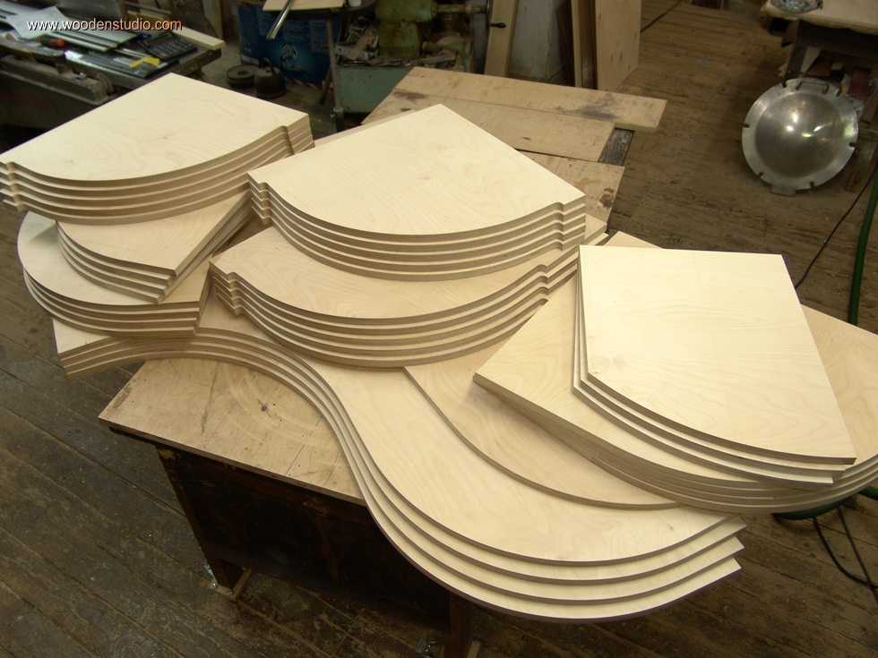
Rip fence for straight and curved cuts
It is possible to ensure the stability of the router when processing narrow surfaces without special devices. This problem is solved with the help of two boards, which are attached on both sides of the workpiece in such a way as to form one plane with the surface on which the groove is made. The milling cutter itself, when using this technological method, is positioned using a parallel stop.
In the presence of a milling machine, work on inserting loops, forming complex holes, recesses, woodcarving, etc. is really simplified. But this does not mean at all that it is necessary to have professional and expensive equipment: it is enough to have a simple manual device.
The only thing you need is to be able to handle wood and use power tools. In addition, you need to have a desire, otherwise there will never be a result without it. Those who have no desire to work simply buy furniture or hire craftsmen to, for example, install a new door and embed locks. Any work, especially with a power tool, requires certain knowledge, and especially safety precautions.

The milling device is intended for processing both wood and metal. With its help, it is possible to form recesses or holes of any configuration. This greatly simplifies tasks such as tapping hinges and tapping locks. To do this with a chisel and an electric drill is not so easy, and it takes a lot of time.
There are stationary milling devices and portable (manual). Manual electric cutters are considered universal devices, with the help of which, in the presence of nozzles, it is possible to perform operations for various purposes, it is enough just to change the position of the part relative to the device or vice versa.
Stationary devices are used in factories or factories where mass production of wood or metal products is established. Under such conditions, the cutting nozzle is stationary, and the workpiece moves along the desired path. When using a hand tool, on the contrary, the part is fixed motionless and only then it is processed, although there are parts that require fixing a hand tool. This is provided for in the design, therefore, it is considered more universal. This is especially true when you need to process a large number of parts, and it is not possible to use a stationary machine.
 Homemade milling machine - a horizontal platform with a hole in the center, from below to which a manual fixture is attached.
 There are many types of milling machines, but for use at home or for starting a business, universal models are more suitable. As a rule, they are equipped with a set of cutters and various devices for performing various kinds of operations. The only thing is that with a manual router, simple operations can take much more time than with a stationary machine.
With the manual milling device it is possible to:
- Make grooves or recesses of arbitrary shape (curly, rectangular, combined).
- Drill through and non-through holes.
- Process ends and edges of any configuration.
- Cut out complex shapes.
- Carry out drawings or patterns on the surface of parts.
- Make a copy of the details, if necessary.
 Copying parts is one of the functions of any electric milling machine.
 The presence of such functions makes it possible to simplify the production of the same type of furniture or the production of identical parts that are not related to the production of furniture. This is one of the main advantages of this tool. As a rule, for the production of the same type of parts, it is necessary to install copy machines that are designed to perform only one operation, which is not always profitable, especially in small enterprises.
Getting Started and Caring for the Instrument
To understand how this device works, you should familiarize yourself with its main parts and their purpose.
Composition and purpose of the main nodes
The manual milling fixture consists of a metal case and a motor, which is located in the same case. A shaft protrudes from the body, on which various collets are put on, serving as adapters. They allow you to install cutters of various sizes. A cutter is inserted directly into the collet, which is fixed with a special bolt or button, which is provided on some models.
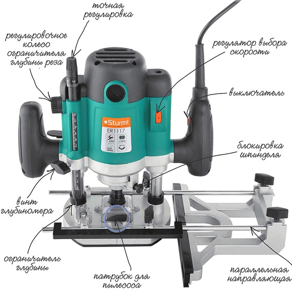 The main elements of a manual milling device and their purpose.
 The design of the milling fixture provides a metal platform, which has a rigid connection with the body. It is attached to the body with two rods. From outside the plate has the smooth covering providing smoothness of the movement in the course of work.
The manual milling fixture has some characteristics that can be adjusted:
- Due to the handle and scale setting the depth of milling. Adjustment is carried out in increments of 1/10 mm.
- By adjusting the speed of rotation of the cutter.
At the initial stages, when the tool is mastered, it is better to try to work at low or medium speeds. Although you should always remember that the higher the speed, the better the work. Especially when it comes to responsible, visible areas that cannot be masked.
In addition to these levers, there is also a button for turning the product on and off, as well as a lock button. These elements are considered the main ones that ensure the quality and safety of work. There is also a parallel stop, which contributes to ease of use. It can be rigidly fixed or with the ability to adjust the shift of the working area, in the direction from the center.
Caring for your handheld router

Usually, a factory product falls into the hands of a person tested and lubricated, so no additional measures should be taken. Only in the process of its operation it is necessary to monitor its cleanliness and serviceability. At the same time, it should be regularly cleaned of dust and change the lubricant, if the passport says so. Especially lubrication is needed for moving parts. Alternatively, you can use aerosol lubricants, but you can get by with the usual ones, such as Litol. The use of thick lubricants is not recommended, as chips and dust stick to them. If aerosol lubricants are used, then this factor can be eliminated.
Lubrication also requires a sole - a smooth part of the body. Regular lubrication will ensure the desired smoothness of movement.
Despite this, the purchased item should definitely be checked for build quality and the presence of lubrication.
Unfortunately, not all manufacturers, and especially domestic ones, care about build quality. There are cases when, after the first hours of operation, screws or screws are unscrewed from the product, as they were not tightened properly.
Rotation speed adjustment
The operation of any tool is associated with certain conditions related, first of all, to the nature of the material being processed. It can be plywood, composite material or regular wood. Depending on this, the rotation speed on the electrical appliance is set. As a rule, the technical data sheet always indicates the operating parameters of the device, depending on the technical characteristics and characteristics of the surfaces to be processed, as well as the cutters used.
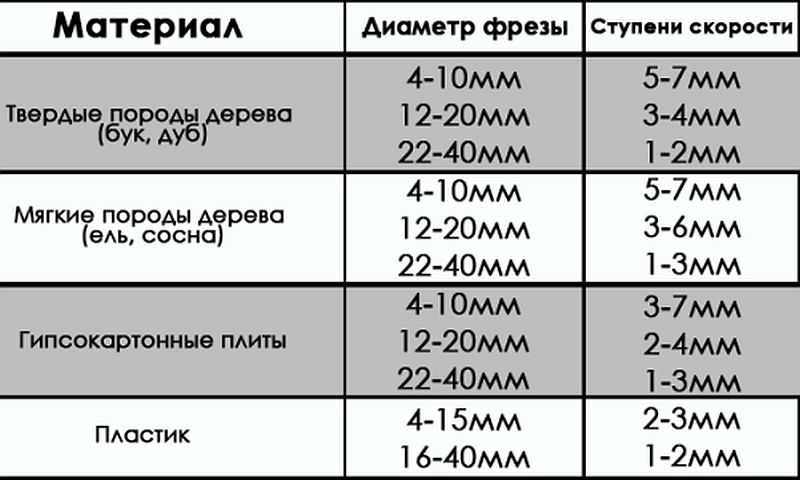 Processing speed indicators when using various cutters.
 Cutter fixation
The first thing the work begins with is the installation and fixing of the cutter. At the same time, one should adhere to the basic rule - all work is carried out with the cord removed from the outlet.
The cutter is set according to certain marks, and if they are absent, then to a depth not less than ¾ of the length of the cutter itself. How to install the cutter on a specific model, you can learn from the instructions, which must be present in the technical documents for the device. The fact is that each model can have its own design features and it is not possible to talk about this in the article.
 Installing the cutter on the device before starting work.
 There are models both simple and more "advanced", as they say. Some models have a shaft rotation lock button, which makes it easier to install the cutter. Some, especially expensive models, are equipped with ratchets. So it’s impossible to describe specifically the process of installing the cutter, and it doesn’t make sense, since everyone who is familiar with the operation of such devices will figure it out at the moment.
Milling depth adjustment
Each model has its own maximum cutting depth. At the same time, it is not always the maximum depth that is required, but a certain depth, which is set before work. Even if the maximum depth is required, then, in order not to overload the device, the milling process is divided into several stages, changing the milling depth in steps. For adjustment, special stops are provided - limiters. Structurally, they are made in the form of a disk located under the bar, on which stops of various lengths are fixed. The number of such legs can be from three to seven, and this does not mean that the more of them, the better. It is better if it is possible to adjust each of the legs, even if their number is minimal. To fix this stop in the optimal position, you should use the lock, in the form of a flag.
The milling depth adjustment process is as follows:

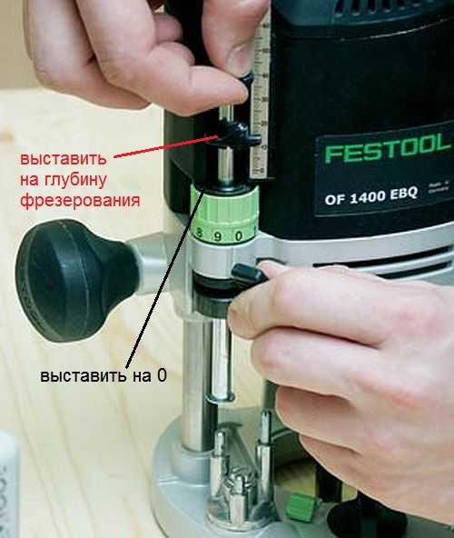 Thus, the workpiece is milled to a predetermined depth.
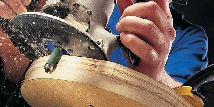
 On high-quality expensive models, there is a wheel for fine-tuning the depth of milling.
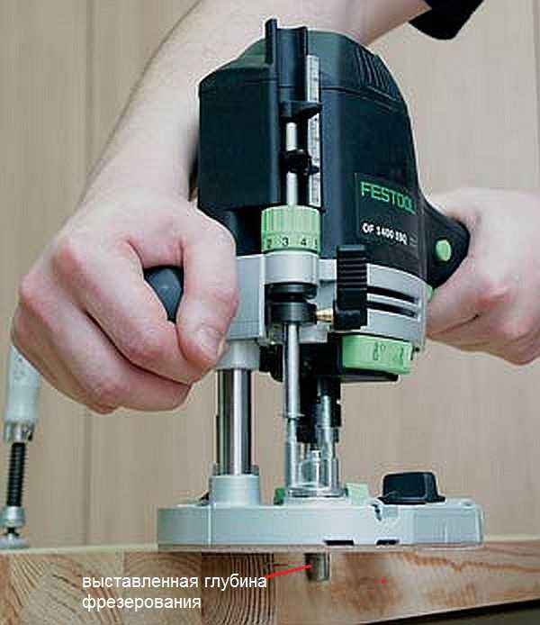 With this wheel, you can more accurately set the depth without violating the previous setting.
 This wheel (green in the photo above) allows you to adjust the depth in a small way.
Cutters for manual milling tools

A milling cutter is a cutting tool that can have an intricately shaped cutting edge. As a rule, all cutters are designed for rotational movements, therefore they have a cylindrical shape. The shank of the cutter, which is clamped in the collet, has the same shape. Some cutters are equipped with a thrust roller, so that the distance between the cutting surface and the workpiece remains constant.
Milling cutters are made only from high-quality metals and their alloys. If you want to process soft woods, then HSS cutters will fit, and if you need to process hard wood, then it is better to use cutters from harder HM grades.
Each cutter has its own technical characteristics, which provide it with high-quality and long work. The main indicator is the maximum speed of its rotation, which should never be overestimated, otherwise its breakdown is inevitable. If the cutter is dull, then you should not try to sharpen it yourself. Sharpening of cutters is carried out on special, expensive equipment. After all, it is necessary not only to sharpen the cutter, but also to maintain its shape, which is no less important. Therefore, if the cutter, for some reason, has become dull, then it will be cheaper to buy a new one.
The most popular cutters
There are cutters that are used in the work more often than others. For example:

 Groove molds are designed to create recesses in an arbitrary place on the workpiece.
 There are simple cutters, monolithic, made from a single piece of metal, and there are type-setting. Type-setting cutters consist of a shank, which serves as the basis for a set of cutting elements. By selecting cutting planes and installing them on the shank, using washers of various thicknesses, it is possible to form an arbitrary relief on the surface of the workpiece.
 A type-setting cutter is a set of cutting surfaces and washers, which allows you to assemble the cutter of the desired shape.
 In fact, there are a lot of cutters and this is only a small fraction of what is produced. All cutters differ in shank diameter, cutting surface diameter, cutting height, knife position, etc. As for manual milling equipment, it is enough to have a set of five most popular milling cutters. If necessary, they can be purchased at any time.
Rules for working with manual milling tools
Working with power tools requires special rules, especially when there are rapidly rotating elements. In addition, as a result of the work, chips are formed, which scatter in all directions. Despite the fact that most models are equipped with a protective shield, this does not fully protect against the flow of chips. Therefore, it is better to work with such a tool in protective glasses.
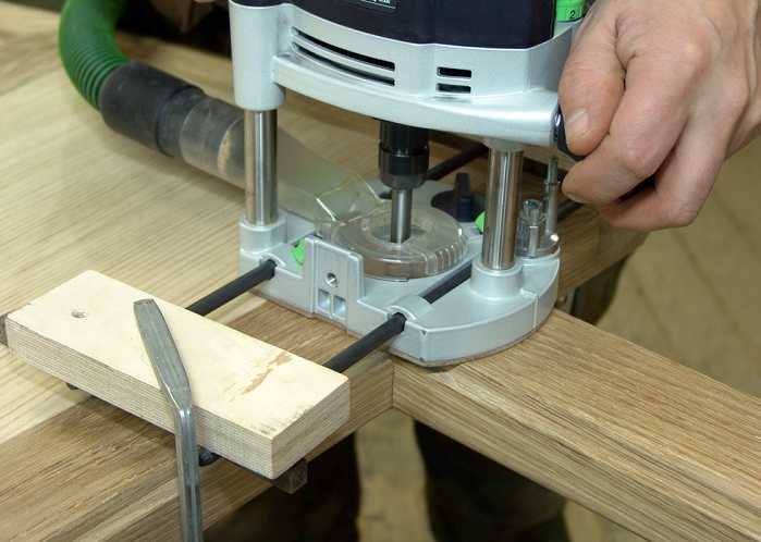 The photo shows a model where a vacuum cleaner is connected to remove chips.
 General requirements
If you fulfill the basic requirements for safe work with an electric hand router, then the end result will please you with the quality of work and a safe outcome. Here are the conditions:

The requirements are not very difficult and quite feasible, and ignoring them means putting yourself in danger. And one more thing, no less important, is the ability to hold a milling tool in your hands and feel how it works. If serious vibrations are felt, then you need to stop and analyze the reasons. It is possible that the cutter is dull or a knot is caught. Sometimes it is required to correctly set the speed of rotation of the cutter. Here you can experiment: either add speed or reduce it.
Edge Processing: Using Templates
Processing the edge of a wooden board is best done on a thickness gauge. If this is not possible, then you can use a manual router, although this will take some time. These works are carried out both without a template and with a template. If there are no skills or there are very few of them, then it is better to use a template. For processing edges, straight edge cutters are used, both with one bearing at the end of the cutting part, and with a bearing at the beginning (see photo).
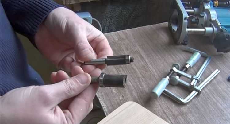 Edge cutters.
 For the template, you can take an already processed board or another, even object. Moreover, the length of the template must be greater than the length of the workpiece, both at the beginning and at the end of the workpiece being processed. This will avoid unevenness at the beginning of the edge and at its end. The most important thing here is that the template or object acting as a template has a smooth and even surface. In addition, its thickness should not be greater than the gap between the bearing and the cutting part.
The width of the part is less than the length of the cutting part
At the same time, the longer the cutting part, the more difficult it is to work with the tool, since more effort is required. In this regard, it is better to start work with cutters that have an average length of the cutting part. The working principle for edge processing is as follows:
- The template is attached so that it is at the desired height and has a flat horizontal surface.
- The template is firmly mounted to a table or other surface.
- The cutter with a roller is installed so that the roller moves along the template, and the cutter (cutting part) along the workpiece. To do this, perform all the necessary manipulations with the template, workpiece and tool.
- The cutter is set in working position and clamped.
- After that, the tool turns on and moves along the template. In this case, it is necessary to determine the speed of movement, which is determined by the depth of processing.
- The milling unit can be both pushed and pulled: as it is convenient for anyone.
After the first pass, you should stop and evaluate the quality of work. If necessary, another pass can be made by adjusting the position of the tool. If the quality is satisfactory, then the clamps are removed, freeing the workpiece.
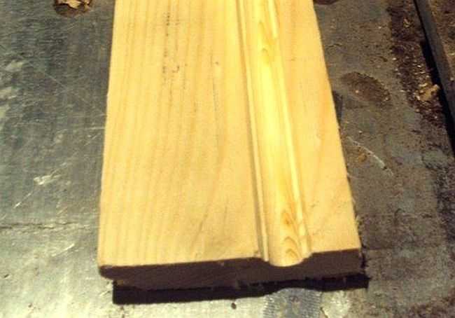
With this approach, it is possible to remove a quarter along the edge or in some of its parts. This is done by setting the cutting edge so that it goes to the required depth into the part.
 A quarter taken on a furniture facade.
 If you replace the cutter with a figured one and shift the guide, as well as use the stop, you can actually apply a longitudinal pattern to the part (in the photo below).
 Drawing a longitudinal figured pattern on the workpiece.
 If you use a similar milling technique (with a template), you can easily master the technique of working with wood in general. After some time, you can abandon the templates, as their installation takes a lot of useful time.
 How to make a smooth edge without a template: experience is indispensable here.
 The width of the part is greater than the length of the cutting part
Quite often, the thickness of the workpiece is greater than the length of the cutting part of the cutter. In this case, proceed as follows:
- After the first pass, the template is removed and another pass is made. In this case, the already processed part will serve as a template. To do this, the bearing is guided over the machined surface. If the cutting part was again not enough, then you will have to make another pass.
- For final processing, you should take a cutter with a bearing at the end, and the workpiece must be turned upside down, after which it is fixed with clamps. As a result, the bearing will move over the machined surface. This approach allows processing thick parts.
 The bearing is guided over the machined surface while the cutting edge machine the rest of the workpiece.
 In order to master the work of a manual milling tool, you will need a lot of rough workpieces, which you do not mind throwing away later. Nobody got it right the first time. For something to work out, you need to train hard.
Obtaining various curly edges
If a curly edge is required, which is most likely to be necessary, then first pay attention to the condition of this edge. If it is uneven, then it will have to be leveled and only then proceed to the formation of a curly edge, choosing the appropriate cutter.
 Rounded edge.
 It is necessary to prepare the surface so that the cutter does not copy the curvature along which the roller will move. In this case, a sequence of actions is needed, otherwise a positive result will not work.
For full-fledged work with a manual router, in addition to the tool itself, the material and the corresponding set of cutters, it is necessary to have one more component - fixtures. In order for the cutter to form the workpiece in accordance with the master's intent - cutting the material exactly where it is required - it must be in a strictly defined position relative to the workpiece at any given time. To ensure this, numerous devices for a manual milling cutter serve. Some of them - the most necessary ones - are included in the instrument delivery set. Other milling devices are purchased or made by hand. At the same time, home-made devices are so simple that for their manufacture you can do without drawings, using only their drawings.
Parallel stop
The most used device, which comes with the kit for almost every router, is a parallel stop, which ensures the rectilinear movement of the cutter relative to the base surface. The latter can be a straight edge of a workpiece, a table or a guide rail. The parallel stop can be used both for milling various grooves located on the face of the workpiece, and for processing edges.Parallel stop for a manual router: 1 - stop, 2 - rod, 3 - router base, 4 - rod stop screw, 5 - fine adjustment screw, 6 - movable carriage, 7 - movable carriage stop screw, 8 - pads, 9 - screw stop stop.

To set the device in working position, it is necessary to push the rods 2 into the holes of the frame 3, providing the necessary distance between the support surface of the stop and the axis of the cutter, and fix them with the locking screw 4. For precise positioning of the cutter, you need to release the locking screw 9 and turn the fine adjustment screw 5 set the cutter to the desired position. For some models of the stop, the dimensions of the supporting surface can be changed by shifting or expanding the support pads 8.
If one simple part is added to the parallel stop, then with its help it is possible to mill not only straight, but also curved grooves, for example, to process a round workpiece. Moreover, the inner surface of the bar located between the stop and the workpiece does not have to have a rounded shape, repeating the edge of the workpiece. It can also be given a simpler form (Figure "a"). In this case, the trajectory of the cutter will not change.

Of course, the usual parallel stop, thanks to the recess in the center, will allow you to orient the router along the rounded edge, however, the position of the router may not be stable enough.
The guide bar is similar in function to the rip fence. Like the latter, it provides a strictly rectilinear movement of the router. The main difference between them is that the bar can be set at any angle to the edge of the workpiece or table, thus providing any direction of movement of the router in the horizontal plane. In addition, the tire may have elements that simplify the performance of certain operations, for example, milling holes located at the same distance from each other (with a certain step), etc.
The guide rail is attached to the table or workpiece with clamps or special clamps. The tire can be equipped with an adapter (shoe), which is connected to the base of the router with two rods. Sliding along the profile of the tire, the adapter sets the rectilinear movement of the cutter.
Sometimes (if the distance of the tire from the router is too close), the bearing surfaces of the tire and the router may be in different planes in height. To align them, some routers are equipped with retractable support legs that change the position of the router in height.
Such a device is easy to do with your own hands. The simplest option is a long bar fixed to the workpiece with clamps. The design can be supplemented with side stops.

By placing a bar on two or more aligned blanks at once, they can be grooved in one pass.

When using a bar as a stop, it is inconvenient to place the bar at a certain distance from the line of the future groove. This inconvenience is devoid of the following two devices. The first is made from boards and plywood fastened together. In this case, the distance from the edge of the stop (board) to the edge of the base (plywood) is equal to the distance from the cutter to the edge of the router base. But this condition is met only for a cutter of the same diameter.. Thanks to this, the device quickly aligns with the edge of the future groove.

The following fixture can be used with cutters of different diameters, plus when milling, the router rests with its entire sole, and not half, as in the previous fixture.


The stop is aligned along the edge of the hinged board and the center line of the groove. After fixing the stop, the folding board leans back, making room for the router. The width of the folding board, together with the gap between it and the stop (if any), must be equal to the distance from the center of the cutter to the edge of the router base. If you focus on the edge of the cutter and the edge of the future groove, then the device will work with only one cutter diameter.
When milling grooves across the fibers, at the exit from the workpiece, when milling an open groove, cases of wood scuffing are not uncommon. The following devices will help minimize scuffing, which press the fibers at the exit of the cutter, preventing them from chipping off the workpiece.


Two boards, strictly perpendicular, are connected with screws. Different cutters are used on different sides of the stop so that the width of the groove in the fixture matches the width of the groove of the part to be milled.
Another open slot milling fixture can be pressed tighter against the workpiece to further minimize burrs, but it only fits a single diameter cutter. It consists of two L-shaped parts connected on the workpiece with clamps.


Copy rings and templates
A copy ring is a round plate with a protruding collar that slides along the template and provides the necessary trajectory for the cutter. The copy ring is attached to the sole of the router in various ways: it is screwed into a threaded hole (such rings are in the photo below), the antennae of the ring are inserted into special holes on the sole or screwed.

The diameter of the copy ring should be as close to the diameter of the cutter as possible, but the ring should not touch the cutting parts of the cutter. If the ring diameter is larger than the cutter diameter, then the template must be smaller than the finished parts to compensate for the difference between the cutter diameter and the copy ring diameter.

The template is fixed on the workpiece with double-sided tape, then both parts are pressed with clamps to the workbench. When you have finished milling, check that the ring is pressed against the edge of the template during the entire operation.
You can make a template for processing not the entire edge, but only for rounding the corners. In this case, using the template shown below, it is possible to make roundings of four different radii.


In the figure above, a cutter with a bearing is used, but the template can also be used with a ring, only either the ring must exactly match the diameter of the cutter, or the stops should make it possible to move the template away from the edge by the difference in the radius of the cutter and the ring. This also applies to the simpler version shown below.


Templates are used not only for milling edges, but also for grooves on the plate.

The pattern can be adjustable.


Template milling is a great method for cutting grooves for hinges.


Devices for milling round and elliptical slots
Compasses are intended for the movement of a milling cutter on a circle. The simplest device of this type is a compass, consisting of one rod, one end of which is connected to the base of the router, and the other has a screw with a pin at the end, which is inserted into the hole that serves as the center of the circle along which the cutter moves. The radius of the circle is set by the displacement of the rod relative to the base of the router.
It is better, of course, that the compass was made of two rods.

In general, compasses are a very common device. There are a large number of branded and home-made devices for circumferential milling, differing in size and ease of use. As a rule, compasses have a mechanism that provides a change in the radius of the circle. Usually it is made in the form of a screw with a pin at the end, moving along the groove of the device. The pin is inserted into the center hole of the part.


When it is necessary to mill a circle of small diameter, the pin must be located under the base of the router, and for such cases other devices are used that are attached to the bottom of the base of the router.

Ensuring the movement of the cutter in a circle using a compass is quite simple. However, one often has to face the need to perform elliptical contours - when inserting mirrors or oval-shaped glasses, arranging arched-type windows or doors, etc. Device PE60 WEGOMA (Germany) is designed for milling ellipses and circles.


It is a base in the form of a plate, attached to the surface using vacuum suction cups 1 or screws, if the nature of the surface does not allow fixing with suction cups. Two shoes 2, moving along intersecting guides, ensure the movement of the router along an elliptical path. When milling a circle, only one shoe is used. The fixture kit includes two mounting rods and a bracket 3, with the help of which the router is connected to the plate. The grooves on the bracket allow you to install the router in such a way that its supporting surface and the base of the plate are in the same plane.
As you can see from the photos above, the milling cutter was used instead of a jigsaw or band saw, while, due to the high speed of the cutter, the quality of the machined surface is much higher. Also, in the absence of a manual circular saw, the router can replace it.
Devices for milling grooves on narrow surfaces
Grooves for locks and door hinges, in the absence of a milling cutter, are performed using a chisel and an electric drill. This operation - especially when making a groove for an internal lock - takes a lot of time. Having a milling cutter and a special device, it can be done several times faster. It is convenient to have such a fixture that allows milling slots of a wide range of sizes.To make grooves in the end, you can make a simple fixture in the form of a flat base attached to the sole of the router. Its shape can be not only round (according to the shape of the base of the router), but also rectangular. On both sides of it, you need to fix the guide pins, which will ensure the rectilinear movement of the router. The main condition for their device is that their axes are in line with the center of the cutter. If this condition is provided, the groove will be located exactly in the center of the workpiece, regardless of its thickness. If it is necessary to move the groove to one side or another from the center, a bushing with a certain wall thickness must be put on one of the pins, as a result of which the groove will shift in the direction from which the pin with the bushing is located. When using a router with such a device, it must be driven in such a way that the pins are pressed on both sides to the side surfaces of the part.

If you attach a second parallel stop to the router, you will also get a device for milling grooves in the edge.

But you can do without special devices. For the stability of the milling cutter on a narrow surface, boards are fixed on both sides of the part, the surface of which should form a single plane with the surface to be machined. When milling, the router is positioned using the parallel stop.

You can make an improved version that increases the area of \u200b\u200bsupport for the router.


Device for processing balusters, pillars and other bodies of revolution
The variety of work that is performed by a manual milling cutter sometimes dictates the need for independent manufacture of devices that facilitate the performance of certain operations. Branded devices are not able to cover the entire range of work, and they are quite expensive. Therefore, home-made fixtures for a router are very common among users who are fond of working with wood, and sometimes do-it-yourself fixtures either outperform branded counterparts or have no branded counterparts at all.Sometimes there is a need to mill various grooves in the bodies of revolution. In this case, the device shown below may be useful.


The device is used for milling longitudinal grooves (flutes) on balusters, poles, etc. It consists of a body 2, a movable carriage with a milling cutter 1, a disk for setting the angle of rotation 3. The device works as follows. The baluster is placed in the body and fixed there with screws 4. Turning to the desired angle and fixing the workpiece in a strictly defined position is provided by disk 3 and locking screw 5. After fixing the part, the carriage with the router is set in motion (along the guide rails of the body), and milling a groove along the length of the workpiece. Then the product is unlocked, rotated to the required angle, locked and the next groove is made.
A similar fixture can be used instead of a lathe. The workpiece must be slowly rotated by an assistant or a simple drive, for example, from a drill or a screwdriver, and excess material is removed by a milling cutter moving along the guides.
Stud milling fixtures
Tenon cutters are used for milling the profile of tenon joints. In the manufacture of the latter, greater precision is required, which is almost impossible to provide manually. Tenoning devices allow you to quickly and easily profile even complex joints such as dovetails.
The figure below shows an industrial sample of a tenoning device for the manufacture of three types of connections - "dovetail" (deaf and through version) and through connection with a straight tenon. Two mating parts are installed in the fixture with a certain shift relative to each other, controlled by pins 1 and 2, then they are processed. The exact trajectory of the cutter is set by the shape of the groove in the template and the copying ring of the router, which slides along the edge of the template, repeating its shape.


When using the content of this site, you need to put active links to this site, visible to users and search robots.
Now it is very difficult to imagine any plumbing event without the use of a milling cutter. But not so long ago, people made grooves, made three-dimensional figures with the help of a planer, chisel and hacksaw. In modern times, various milling devices, including those made independently, are becoming increasingly popular. Do-it-yourself templates for a router make it easier to control the mechanism, help to process surfaces as accurately and accurately as possible.
Such a device is necessary where you need to make a hole, smooth the edge of the product, cut out a three-dimensional figure. Milling is used when cutting ornaments, patterns, preparing niches for installing corners, locking mechanisms, hinges. This tool allows you to remove the chamfer, round the edge of any part. According to its characteristics, the milling cutter resembles the actions of a planer.
This processing attachment works with wood, plastic and aluminium. However, each of the cases involves the installation of predetermined speed modes and appropriate equipment. Despite the active use of the milling cutter, such attributes of building significance as a chisel, a hacksaw, a cutter are still used in the work. The use of templates for these installations is often associated with furniture making.
Making a homemade furniture template

Any employee of a furniture organization knows perfectly well how difficult it is to make a corner kitchen. Installing a countertop requires precise joints, rounding the leading edge and flattening other parts. It is known that a flat edge, attached in the form of a rounded beginning, will acquire an unsympathetic appearance with a noticeable rough seam. In order for the trimming to be carried out correctly and accurately, a milling device and a specially made template for furniture are used. Creating such samples yourself is not so difficult.
The main devices, without which installation will be impossible, will be:
- fiberboard sheet;
- manual milling mechanism;
- blueprints.
Back to index
Step-by-step production of a template for furniture

Pieces of furniture, sawn according to the pattern, have the same shape and size.
- Such a template, made by hand, will perform its functions no worse than purchased in a store. To create it, you need to prepare a drawing and a cover for the processing machine. Then a trial homemade product is made from a fiberboard sheet, its thickness is equal to 8 mm.
- Next, the diameter of the cutter and the machine itself are measured. Then 2 intersecting lines are drawn, the angle of which is 135°. To smooth these indicators, an arc is taken. To calculate its radius, you should find out similar indications for the cutter and rings. From the value of the first device, the resulting difference in the radii of the rings and cutters should be subtracted.
- It turns out the inner arc. At its base, a smooth end face of postforming is milled. As the ring moves along a given radius, the cutter describes such an arc, the diameter of which is equal to its own.
- From the drawn segment, 2 lines are laid, parallel to each other. The distance between these points is equal to the diameter of the ring of the router used. 5 mm is added to these indications. The line originates from the middle of the previous arc.
- The connection point of the segments is smoothed with an arc. Its radius corresponds to similar indications of the device thrust ring. During the movement, the cutter will no longer be able to perform arcuate movements.
- You need to draw 2 equivalent rectangles imitating the contours of the countertop. An angle is superimposed on them, after which it is lengthened by a certain distance.
- The marks put on the template will greatly simplify the work. The arcs of the upper and lower rows will not be combined. Therefore, it is necessary to reconcile for each detail slightly shifting these boundaries.

Back to index
Templates for a manual router
- The first step is to make a template from hardboard hardwood, the thickness of which is equal to 6 mm. The height of the MDF stencil is 12 mm. These materials are very easy to process and are in no way inferior to wood. However, their corners buckle easily from accidental bumps or drops. In order for the templates to serve for a long time, it is necessary to take a high quality birch. Despite its high cost, unlike MDF, it has greater strength and constancy of characteristics.

On the surface of the template, the boundaries of the parts are drawn in compliance with natural proportions. Then starting grooves are drilled, unnecessary material is cut with a jigsaw, observing a 1 mm indent near the contour line. The edges of the edge are carefully polished, the paper stencil is removed.
- Using a template, a given number of parts is created. Then this element is placed on the product and outlined with a pencil. Unnecessary material is cut out, moving away from the contour by 1.5 mm. Similar actions are carried out with other blanks.
- With the help of double-sided adhesive tape based on fabric, the template is fixed on one of the products. To make the work go as quickly as possible, insert a cutter with a bearing on the shank into the collet of the machine. This part rolls along the edge of the stencil.
- Then you need to select the type of cutter. All varieties with bearings are used for milling according to templates, the device is held in the hand and installed on the surface. With the help of a copy cutter, the operation of the machine is controlled at the moment when the part moves along the table, the template is located on top.
- The space between the tip and the shank does not need to be machined with a bearing cutter in one pass. This can be done in 2-3 times, using a cheaper version of the cutter. Milling is carried out when the bearing is aligned with the middle part of the stencil thickness.
- A thrust rod device is placed close to the cutter. The machine is turned on, the part is pressed against this part and gradually moves towards the rotating cutter until the bearing comes into contact with the template. Milling of external contours is carried out counterclockwise, internal outlines - in the opposite direction. At the moment of contact of the cutter bearing with the template, the part is removed from the rod thrust device.
The copying device at the shank functions similarly, however, it is required to rotate the part so that the stencil looks at the surface of the table. Milling is carried out similarly to the table. In the process of carrying out the manipulations, it is important to monitor the integrity of the base of the workbench.
Back to index
Wedge Templates for Hand Router

You can make a template in the form of spikes or wedges on your own. This connection is distinguished by elegance and is most often used in the manufacture of furniture. And there, as you know, high build quality is required. Using such primitive devices as a saw and a chisel in work, one cannot do without a certain experience in the construction industry, which cannot be said about a manual milling cutter. It allows even beginners to carry out the given work.
How do I get the template connection for the router so that it clearly defines the wedges on all the workpieces? To do this, you can use a manual machine with decent characteristics. The ring must be the right size for the machine, otherwise it should be purchased.
A wedge-shaped device of a partially hidden type can be seen from one side. The end-to-end connection can be traced from both points. To combine the two parts, the light element is installed strictly vertically. Periodically, the interdental space of the template is cleaned of sawdust. Upon completion of the work, the existing roughness must be processed with an emery cloth.
One of these devices is a parallel stop. This is a component of the basic set of any router, and the owner of the tool does not have to make the stop himself. It is needed for the direct following of the cutter along the surface of the base, which can be the smooth edge of the part or workbench.
The stop allows you to process edges and grooves, firmly fixing the part.
This useful addition to the milling tool consists of the following parts:
- rods included in the recesses on the milling cutter;
- screw fasteners tightening them in the desired position;
- adjusting screw for fine adjustment of the distance of the cutter axis from the edge;
- the supporting part that holds the structure on the base.
To bring the stop for the wood router to readiness, it is necessary that the rods take up position in the recesses on the tool body and are tightened with a stopper. By loosening the stopper, you can make small adjustments if necessary with the adjusting screw.
With a slight addition, the parallel stop allows you to make, in addition to straight cuts, more complex ones. Adding this is a wooden block with one even side. The other side has an angular or round notch. The bar is inserted between the supporting part and the edge of the material, which has a curved shape.
The bar is in contact with the support with its even edge. The side where the notch is in contact with the curved base. Manipulate the tool with such a device should be extremely careful, as the bar introduces an element of instability.
Guide bar
Having a similar purpose to the rip fence, the tire is responsible for the accurate running of the cutter in a straight line. The time spent on work is significantly reduced due to the use of the tire. It also allows you to guide the tool on the table at any angle to the edge.
Note! You can fix the tire on the countertop or material with clamps.
Some serial production tires have a separate component in the kit - a shoe. It is connected to the router with rods and, passing along the tire, moves the milling head along a given trajectory.
The tire is best combined with a tool whose base is on retractable legs. This eliminates the difference in height between the bar and the router.
It happens that the functionality of mass-produced tires does not suit the user. You can always create an individual version of the guides for the router with your own hands. The most elementary is a long, even bar - in other words, a ruler. The master only needs to provide it with fasteners, and the tire, in fact, is ready. For the manufacture of a simple fixture, a drawing is not even required.
Of course, such a homemade version will not be sustainable. A combination of a plywood base with a board nailed to it will turn out to be more stable in work. The edge of the milling base will rest against the board, and the edge of the base will indicate the processing area. This design is used in the case of using cutters of the same diameter.
Another option works when wood cutters can be of different sizes. Here, the board, acting as a ruler, is not nailed to the base, but is reinforced with clamps. Thanks to this, it can adjust the distance from the working area according to the diameter of the cutter.
Templates and copy sleeve
The copy ring is a circle with a ledge that slides on a pattern, guaranteeing the accuracy of processing. The ring can be screwed to the base of the router or secured with antennae. The diameter of the fixture is selected in such a way that it does not come into contact with the working part of the tool.
The ring template is fixed on the processed material, firmly adjoining to a table-top. Reliable clamping is provided with double-sided tape and clamps. After finishing the part, you need to make sure that the bushing fits snugly along the edge of the template when working.
A do-it-yourself template for a router will also be used for processing the corners of a part, when it is necessary that they be round. Depending on the location and dimensions of the template, the radius size of the rounding can be any.
The template design often includes bearings or rings. If this is a ring, then it should be selected according to the size of the cutter. With a difference in diameters, it is necessary to add stops to the design of the template, with which it will be possible to move the fixture from the edge of the part.
Among the auxiliary devices for the router, the most flexible templates, in addition to processing the edges of the material, also allow cutting complex grooves. The special arrangement of the accessory makes it possible to effectively create recesses for door hinges. With the help of a template, you can even carry out decorative work with a router, for example, cut out wooden patterns.
Compass
This auxiliary tool is designed to create round and oval cutouts. The basic compass scheme includes a rod with a pin fastening at the end. By inserting the fastener into the hole in the center of the circle along which the groove is made, you can change the size of the circle by simply moving the rod.
Note! The convenience and reliability of the design is enhanced by the addition of a second rod.
There are various auxiliary elements that work on the circular principle. They give the advantage of creating different radii of circular grooves. An obligatory component of such auxiliary devices is a pin with a screw for adjusting the length of the radius.
If a small hole is being cut, the circular design must be adapted to fit on the base of the router. The pin when machining the part is located directly under the tool.
A wood router, in addition to round ones, is also able to cut elliptical holes. The device for this can be assembled with your own hands from the following parts:
- base with fixation on the material of screws or suction cups;
- shoes moved on crossed guides - 2 pcs.;
- rods for mounting - 2 pcs.;
- bracket for connecting the structure to the tool.
The fastening bracket, thanks to the grooves intended for this, allows the frame of the structure to be in the same plane as the base of the router. Cutting round openings is done using one shoe. If you need an oval hole, both are used. This auxiliary design makes it possible to make holes more accurately and faster than other tools such as a band saw or a jigsaw.
For grooves on narrow surfaces
Recesses for locks or door hinges can also be made with a drill and a chisel, but a router is much better suited for this. You just need to equip the tool with a certain device. It consists of a flat plate that is attached to the base of the device. The shape of the plate can be round or rectangular. 2 pins are made on it, ensuring a smooth running of the tool during operation.
The main parameter that must be followed in the manufacture of such an element is that the axis of each pin must be on the same line as the center of the cutter. Subject to this parameter, the groove will be cut exactly in the middle of the workpiece, regardless of the thickness. If it is necessary to shift the groove to the right or left, a sleeve of the size required for the desired shift is put on the corresponding pin.
Using this design, the router is driven with the pins firmly pressed against both sides of the workpiece.
The same effect is achieved if two parallel stops are used with the router.
Even one stop may be enough. It is necessary to strengthen the workpiece between two surfaces, such as boards, so that all three elements are in the same plane. The problem of insufficient part width in this case is eliminated.
When you often have to work with narrow surfaces, a good solution would be to build a special table from two halves. By clamping the material between them, the master will easily achieve the effect of one plane.
Solids of revolution
When working with round blanks, such as poles or balusters, a structure is made up of a frame, inside which the part is placed, carriages for the milling cutter and a rotary disk. The part is inserted into the frame, securely fixed, after which the carriage with the tool is extended to the area for processing. The position of the part in the frame can be changed by means of a rotary disk.
The same frame with a milling cutter in the carriage can serve as a lathe. All you need to do is turn the disk while the router is moving along the guides. This can be done by an assistant master or a drill connected to the disk.
Tenoning devices
Such devices provide the creation of joints based on spikes. Requiring high precision of material processing, such profiles are easily performed by a milling cutter.
Using a manual router, the master brings it to the material freely. Therefore, the material needs to be securely fastened for error-free tenon cutting.
Such conditions can be created by a simple device made of the following parts:
- rigidly fixed guides, lower upper and side;
- a bar with one degree of freedom, which will limit the sample.
The parameters of the parts depend on the specific tool for which the device will be assembled. The assembly order is as follows.
Equal-sized vertical ribs with cutouts in the center are installed along the edges of the plywood base. Rails are attached to these ribs, on which the tool will move. For the safety of the movement of the router on the rails, they are locked with limiters, which can be simple wooden slats.
A movable part is attached to the plywood base - a regulator for sampling the edge of the part. The latch can be a wing screw or another fastener at the choice of the master.
Regardless of the manufacturer, a hand mill with the addition of such a structure is able to easily cut a simple tenon profile.
Another tool for the production of spikes is the jig. It consists of a base, stops and a movable part in the form of a sled. Already experienced users are starting to manufacture and use it for very small and precise work.
Hidden Features
The listed case of auxiliary tools may seem redundant when the master performs only the simplest operations with a router. But if you look at this tool from the angle of its potential, then a number of directions arise before the user.
Those works that the master did not even think that he could carry out turn out to be quite affordable - one has only to build a few auxiliary structures. As if this is not a simple manual milling cutter, but a CNC coordinate machine.


