Grounding is one of the most important technological methods of protection against electric shock when working with electrical appliances. To properly modernize or repair the wiring, you need to know exactly what grounding system is used at the facility. Human safety and the normal operation of equipment depend on this. Information is also important when creating a renovation project. Accordingly, it is necessary to study all available grounding systems, the differences from each other, as well as the technologies for their installation.
The International Electrotechnical Commission (IEC) and the State Standard of the Russian Federation have established the types of grounding systems. All of them are indicated in the PUE (electrical installation rules). Distinguish:
- TN system (with TN-C subsystems, also TN-S and finally TN-C-S);
- TT system;
- IT system.
They differ in the source of electricity and the method of grounding electrical equipment. The type of grounding system is indicated by the letters:
1. The first letter determines how the power supply is grounded:
- if it is T, then there is a direct connection of the neutral working conductor (neutral) of the power source to the ground;
- if it is I, then the neutral of the energy source is connected to earth exclusively through resistance.
2. The second letter determines the grounding in the conductive open parts of the electrical installation of the building:
- the letter T denotes local (separate) grounding of electrical equipment and power supply;
- the letter N means that the power supply is grounded, but the consumers are grounded only through the PEN conductor.
3. The following letters after N define the functional way in which the zero working and zero protective conductor are arranged:
- if there is S, then the functions of the working (N) as well as the protective (PE) conductors are provided with separate conductors;
- if it is C, then the functions of the neutral working and protective conductors are provided by a common conductor (PEN).
TN system and its variants
The TN system is distinguished by the presence of a solidly grounded neutral: the exposed conductive parts of any electrical installation are connected to a specific solidly grounded neutral point of the power source by means of special zero protective conductors.
The term " solidly grounded neutral»Means that the neutral (zero) at the transformer substation is connected directly to the earth loop (ie grounded).
The main condition for electrical safety TN is as follows: the value of the current between the open conductive part and the phase conductor in the event of a short circuit must exceed the magnitude of the electric current of the protection device for a normalized time.
The highly demanded TN-C subsystem
The TN-C subsystem is TN, in which the conductors (zero working, as well as protective) are combined throughout the system (into 1 PEN conductor), i.e. protective grounding was performed. It is the most used TN variation since Soviet times. However, this system is now outdated. Of modern electrical installations, it is found only in street lighting (for the sake of economy, as well as reduced risk). It cannot be recommended for new housing. Now it has been replaced by more modern systems.
Grounding option TN-S
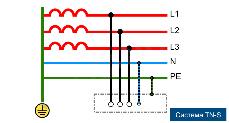
The TN-S subsystem is TN, in which the conductors (zero working, as well as protective) are separated throughout the system. It is the most modern, safest, but most expensive system. It has been used in telecommunication networks for a very long time (which is remarkable, when using it, interference in a low-current network is excluded).
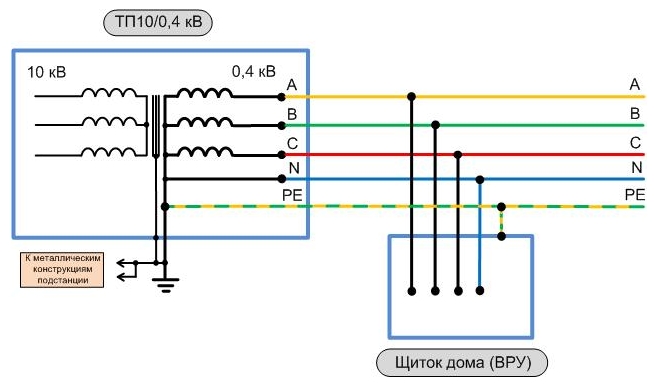
TN-C-S - device specific
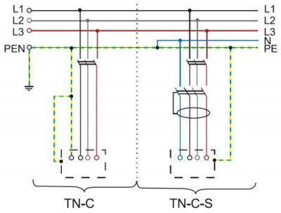
Subsystem TN-C-S - can be classified as an intermediate option. In it, the zero worker, as well as the protective conductors, are combined only in one part of it. Usually - in the main shield of the building (where protective earth supplemented by protective grounding). Throughout the building, these conductors are further separated. The system is optimal in terms of price-quality ratio. This scheme is currently the main one, which can be implemented in individual parts of electrical installations during reconstruction. Other grounding systems for electrical installations do not allow this. The cross-sections of the conductors are selected based on the values \u200b\u200bof the currents (calculated) flowing through them. The cross-sectional area (minimum) of the PEN conductor is 4 mm2. It is necessary to provide that the switchboard has separate terminals on the PEN bus (for each conductor - N and PE). When using a stranded or single wire as a PEN conductor, its insulation color must be exclusively yellow-green.
What is the TT system
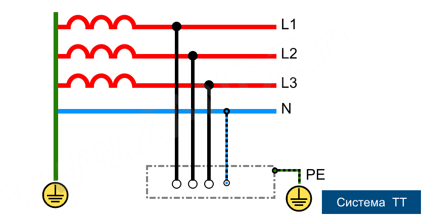
This system differs in that the zero of the source in it is grounded, while the exposed conductive parts of any electrical installation are connected to a ground that is electrically independent of the grounded zero (neutral) of the power source. In other words, the facility uses its own ground loop, which is in no way connected to zero. To date, this system is used as the main one in mobile structures, for example change houses, wagon houses, etc. (where it is not always possible to mount the earthing switch in accordance with the required standards). It is noteworthy that the coordination of its application is more difficult than TN. The use of an RCD becomes mandatory, high-quality grounding is also necessary (namely, 4 Ohm at 380 V), there are many features in the selection of the necessary protective circuit breakers.
IT system: distinctive features
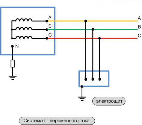
This system differs in that the source zero in it is isolated from ground or grounded through devices that have high resistance, and conductive open parts of electrical installations are grounded using grounding devices. IT is rarely used. Mainly - in electrical installations of buildings for special purposes. For example, for emergency lighting and power supply in hospitals. In general, where there are increased safety and reliability requirements.
Grounding systems technology
There are several technologies for installing a ground loop. The two most commonly used are the traditional and modular pin grounding system.
Traditional technology and materials
Grounding is made of black metal: corners, pipes, strips, etc. Installation begins with the creation of a project that reflects the place where the ground loop will be arranged, the location of technical communications in the ground. Then, focusing on the object, into the soil to a depth of 3 m, at a distance of about 5 m from each other, metal products (electrodes) of a certain section (not< 3-х). После этого эти электроды они свариваются в общий контур по периметру при помощи металлической полосы.
This technology has been mainstream for many decades. However, it has a number of disadvantages (for example, metal corrosion, installation laboriousness, etc.), so now they are trying to replace it with another, more modern and perfect grounding technology.
Modular grounding system

What is included?
- It consists of rods made of high quality steel and covered with copper. They are placed vertically in the ground. Each of these rods reaches a length of about one and a half meters, and in diameter - 14 mm, the mass of the 1st element is no more than 2 kg. On both sides of each rod, a copper-plated thread is cut 30 mm in length.
- The steel elements of this system are interconnected with brass couplings.
- The modular earthing system kit also includes a brass clamp used to connect the horizontal (special steel strips or copper wire running from the distribution box directly to the ground loop of this system) and vertical (copper-plated steel rods) earthing elements.
- The kit also includes two steel tips that will be attached to the rod by screwing onto the copper-plated thread. The tips will have to be chosen depending on the soil (especially hard or normal). It will pass the entire arrangement of this building grounding system.
- For anti-corrosion protection of all grounding elements, a protective paste is usually applied, with which the elements of the entire future grounding system are processed.
- For a safer and more reliable connection of horizontal and vertical components, use a protective tape (for example, PREMTAPE).
How is the installation going?
The installation of a modular pin grounding system takes place in several stages:
- The 1st vertical steel pin is installed.
- The intermediate resistance is measured.
- The rest of the vertical pins are mounted.
- A horizontal earthing switch is laid.
- Then the elements are connected and processed with a protective tape.
Advantages of a modular pin grounding system
- Allows you to save space (can be equipped on 1 m2 of area).
- Simple, does not require labor-intensive earthworks.
- No welding required.
- Such grounding can be used for any type of soil.
- Great depth is achieved - up to 50 m.
- Stainless steel conductors are used.
- No need for special equipment.
- Long service life.
Video: progressive protective circuit
From all of the above, we can conclude that today the most rational is the use of the TN-C-S system and the modular-pin technology of its installation. All the facts indicate that the latest generation grounding device technologies are superior to traditional ones in many respects. Their use reduces the duration of work, reduces financial costs, and increases the service life of grounding elements.
Grounding is a protective circuit system to prevent electric shock when a phase is shorted to the frame. Purpose, types and methods of its installation - these are the main issues facing every homeowner and industrial premises.
A grounding device is a structure equipped with a grounding conductor and grounding conductors.
Types of grounding depending on the distance of the object from the protective circuit
According to this characteristic, the types of grounding devices are subdivided:
- portable;
- contouring device.
Let's analyze each of them in more detail.
Remote device
With this type, the location of the earthing switch is made outside the premises. A remote (concentrated) protective device is mounted if it is impossible to equip the circuit on a site with rocky, stony soil, or if there is a ground quality most suitable for grounding behind the site. The spread of production equipment at a considerable distance from each other is another reason for installing a remote system.
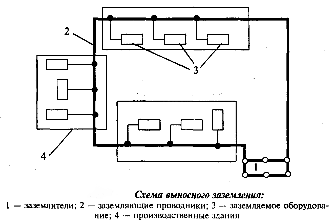
The advantage of this type is the ability to choose an installation site with the best soil properties, with a low level of resistance. Such soils include clay or sandy wet soil. But the method has a significant disadvantage. The value of the conductor tangency factor is 1, due to the distance from production facilities.
This type of protection is installed for servicing objects with low short-circuit currents (no more than kV). The potential voltage when touching the damaged section of the circuit is not less than the potential of the grounding conductors.
Contour device
Grounding electrodes are located evenly, along the boundaries of the contour of the serviced area and on it. Therefore, the second name of this type is distributed. With this method of installing earthing switches, the safety of using the devices is ensured by lowering the potentials on each earthing switch and their potentials are equalized. This method allows the peak short-circuit current to be reduced. Grounding electrodes located on the territory of the contour can solve this problem.
![]()
Each grounding method, with long use, can increase the loop resistance. For early detection of a malfunction, it is necessary to periodically inspect the circuit and tighten the nuts on the wire fasteners.
Re-grounding arrangement
This method allows you to reduce the value of the short circuit current and other damage to wiring and electrical devices, which is dangerous to humans. At the same time, it is a system of grounding electrodes located separately and independent of the main circuit.
The installation provides for the operation in an emergency of the nearest circuit breaker. Most often, an old building with an outdated two-core aluminum wiring is re-equipped. Wiring leads to each consumer from the end contact weld at the base of the circuit. The wires are fixed to the shield body with bolts and nuts with grovers.
Types of grounding depending on the wiring
Before carrying out work on the electrical wiring of the building, it is necessary to make a choice of the method of connecting the earth wire to the in-house network and the type of protection circuit. Here is the decoding of the abbreviations used in the name of the types of cable connections:
- I - insulated wiring;
- N - indicates connection to the neutral wire;
- T is a symbol indicating connection to a ground wire.
The world grounding system has been adopted, which includes three main types.
IT system
Practically inapplicable system in housing construction. With it, a resistance with a large rating is used or through an air gap. This type of grounding is used in laboratory and medical rooms. Serves to provide a high level of protection for equipment and devices that require a significant level of safety and stability during maintenance.
According to the rules of the PUE, for private economic construction, you can use a system with independent grounding conductors.
TT system
The wires are brought to the panel board, at the entrance to the building with two earthing switches. Most often they are used to maintain systems of voltage sources in the network and on the metal covering of the system without insulation. Significant performance indicators of zero wiring at a distance from current transformers to the consumer of electricity.

During installation, difficulties may arise associated with the selection of the diameter of the wiring to ensure the safety of the grounding itself. For these purposes in given view wire connection, a shutdown system is installed.
TN system
This, the most common form of conducting a grounding conductor with a grounding of the neutral wire, allows all current consumers of the building to be connected to the neutral. All equipment is connected to earth ground through the zero wires. All conductive housings, equipment and devices in switchboards and other consumers, in case of a short circuit to the housings, are disconnected from the mains using automatic machines and protect the person in the room from electric shock. It is divided into the following types:
- TN system - 5. Type of grounding and neutral conductor connection with two separate conductors. This method is by far the safest for humans. With this method, the wiring from the power source is carried out using a three-core copper wire with the appropriate cross-section for the given building and the number of consumers. As a rule, a brown or black conductor is used to connect the phase, zero is connected with a blue or blue wire, and a yellow-green color of insulation is used to connect the ground.
- TN-C-S system, in it two wires are supplied to the electrical panel, namely the neutral wire and the phase wire. And already in the dashboard, zero is divided into two conductors, one of which is zero, and the second is grounding wire. To ensure a reliable and safe protection it is required to install an additional disconnect switch in the panel after wiring the conductors.
When using copper stranded conductors in the wiring of an old building that is not equipped with a protective circuit, it appears to equip the power grid with reliable protection.
Such a system protects wiring and household appliances well in the event of a lightning strike. When installing an RCD, the level of human safety is increased. The disadvantages include - installation additional equipment and reduced safety when servicing a country house.
As a result, we present the main points of the article.
The cross-section of the wiring and the choice of the design of the grounding loops are one of the main characteristics when installing one of the types of the grounding loop.
To carry out work on the manufacture of the ground loop, various earthing switches made of artificial or natural metals are used. Based on clause 1,7,109 of the Installation Rules, a reinforced concrete or metal section of a building, protective sheaths of cables located in the ground, pipes immersed in wells and others can be used.
Do not connect ground wires to gas pipelines, sewerage pipes, heating pipelines. But for equalization of current potentials, these sections can be used.
At power electrical network buildings over kW, it must be equipped with a grounding system. Types of grounding are used to ensure the safe operation of the current network, but the resistance value should not exceed 4 ohms.
Earthing switches (grounding stakes driven into the ground to create a ground loop) must be made of copper, galvanized or ferrous metal. All values \u200b\u200bof the dimensions of ground electrodes and other components of the circuit are given in the paragraphs of the PUE.

The horizontal jumper of the ground loop must be buried in the ground for at least half a meter; in the case of light ground, it should be buried for at least one meter. Horizontal jumpers affect the loop resistance more than vertical ground electrodes.
If necessary, a repeated grounding circuit of the electrical network is installed.
When choosing a cross-section, it is necessary to familiarize yourself with, but the ground wire cannot be less than the phase wire.
Grounding will not replace the circuit breaker and RCDs, and they will not be able to do the grounding work.
To avoid electrical shock when touching exposed wiring or damaged electrical equipment, the International Electrotechnical Company (IEC) has developed a special protection called grounding. Also, this system is standardized in GOST RF and a detailed description is available in the book PUE (rules for the construction and operation of electrical equipment). What is the grounding circuit of the electrical network? Everything is very simple, it is an additional device conductor connected to zero. In the event of an accident, when insulation breaks down or a contact appears where it should not be, the phase energy will go to zero through the PE wire, and even in case of accidental contact, the person will not be hurt. Let us analyze what types of grounding systems are used in Russia.
TN and its varieties
The most common type of grounding system is TN, in which the zero is aligned with the ground along its entire length. This type is also called in the supply a solid-grounded neutral, when the conditional zero N of the source is connected to the PE grounding device. The grounding device is not complicated, but nevertheless it is technologically advanced and is a group of pins driven vertically into the ground to a considerable depth to the aquifer, from 2.5 meters or more. These pins are connected by a strip or cable to form a single ground loop for a residential building. Consider what is the classification of TN systems today and what is the difference between all varieties.
TN-C
In the old housing stock, a type of protection is used, this is when zero N also serves as a protective PE conductor, combined. This is the simplest and cheapest option for grounding electrical installations up to 1000 V.
Type TN-C is morally obsolete and electrically dangerous, since it does not have a separate protective conductor, and in the event of an emergency, the entire potential will be on the electrical equipment, exposing it to the risk of electric shock or fire.
TN-S
Therefore, in newly designed buildings, a different subsystem is used, in this device there is a separate phase conductor, zero (neutral) and a protective PE conductor. N and PE conductors, starting from the substation with a solidly grounded neutral, are separate components of the power supply system.
This type is the most reliable of the accepted types of grounding of the electrical network. Its disadvantages include high cost, as it needs an additional conductor from the substation to the consumer.
Devoid of these drawbacks, relatively easy to implement, which combines the advantages of the previously described systems. Also easy to implement when renovating old buildings. The meaning of this scheme is that the TN-C system is organized before the main switchboard, here they divide neutral wire PEN for two conductors N and PE, followed by the TN-S system.
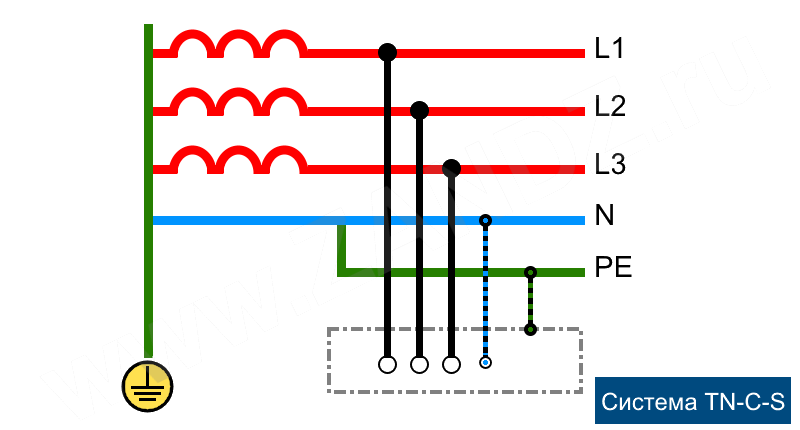
The disadvantage of this system is the same as that of TN-C, if the PEN bus is broken, the system is fully energized. This drawback is fought by installing additional devices, such as those that produce an emergency shutdown of the consumer from the network.
TT and IT
There are two more types of supply that are used in special conditions, this type is when the delivery of electrical energy is organized by phase wires from a source with a dead-grounded neutral, and grounding is organized directly at the consumer. In this way, mobile homes, temporary objects are connected. This type requires the mandatory use of RCD residual current devices.
Another option is a type of supply that does not use a solidly grounded neutral. The zero of the source is connected through special devices with high internal resistance, and a zero and protective grounding device is installed directly at the consumer (according to PUE 7, chapter 1.7). This type of supply is used in special laboratories, since the interference introduced in this way is minimal.

Globalization has not spared electrical engineering, IEC ( International Electrotechnical Company) has developed a unified standard by which grounding systems qualify.
The following three systems can be distinguished, as well as three more grounding subsystems:
- TN system: subsystems TN-C, TN-S, TN-C-S.
- TT system.
- IT system.
The international classification of grounding systems is indicated by capital letters. The first letter indicates the nature of the EARTHING OF THE POWER SUPPLY, the second - the nature of the GROUNDING OF OPEN PARTS OF THE ELECTRICAL INSTALLATION.
Which system reliably protects?
The abbreviation of the letters stands for:
- T (terre - ground) - grounded;
- N (neuter - neutral) - connected to the neutral of the source (nullified);
- I (isole) - isolated.
The GOST introduced the designations of zero conductors:
- N - zero working conductor;
- PE - neutral protective conductor;
- PEN - combined zero working and protective grounding conductor.
Purpose of grounding systems
I propose to disassemble each system and subsystem in order in order to better understand how they work and what they are for.
TN system - a system in which the neutral of the power supply is solidly grounded, and the exposed conductive parts of the wiring are connected to the solidly grounded neutral of the source by means of neutral protective conductors.
The term solidly earthed means that the N (neutral) conductor is connected not to the arc suppression reactor, but to the ground loop, which is directly mounted near the transformer substation.
TN system: TN-C subsystem
TN-C - zero working and zero protective conductors are combined in one conductor throughout the system (C - combined).
Advantages of the TN-C subsystem.
The most common subsystem, economical and simple.
Disadvantages of the TN-C subsystem
Such a system does not have a separate PE (protective earth) conductor. This means that there is no grounding in the outlets in the residential building. Often, with such a system, zeroing is done. Zeroing is an extreme measure designed for the effect of a short circuit. If the phase conductor is on the device case, a short circuit (short circuit) will occur, as a result, the circuit breaker will trip.
With such a TN-C system, potential equalization in the bathroom is unacceptable.
The TN-C grounding system is used in old housing stock and cannot be recommended for new buildings.
TN-C system diagram

TN system: TN-S subsystem
TN-S - zero working and zero protective conductors work separately throughout the system (S - separated).
Advantages of the TN-S subsystem.
The most modern and safe grounding system. Recommended for the construction of new buildings. Promotes good protection of people, equipment, as well as the protection of buildings.
Disadvantages of the TN-S subsystem.
Less common. It requires laying a five-core wire from a transformer substation in a three-phase network or a three-core cable in a single-phase network, which leads to an increase in the cost of the project.
System diagram TN-S

TN system: TN-C-S subsystem
TN-C-S - zero working and zero protective conductors are combined in one conductor in some part of it, starting from the power source to entering the building, such a system can be split into an N conductor and a PE conductor. After splitting, such a system requires re-grounding.
Advantages of the TN-C-S subsystem.
Disadvantages of the TN-C-S subsystem.
Needs modernization of risers in the entrances. If the PEN conductor is interrupted, electrical devices can be at a dangerous potential.

TT system
TT - the neutral of the source is solidly grounded, and the exposed conductive parts of the electrical installation are connected to an earthing switch electrically independent from the neutral earthing switch of the power supply.
Until recently, the TT grounding system was prohibited in our country. Today, this system remains quite in demand and is used for mobile buildings such as trailers, stalls, pavilions, houses, etc. It is allowed only in cases where electrical safety conditions in the TN system cannot be ensured.
Such a system requires high quality re-grounding, with high resistance requirements. The most effective ground in this case is the modular pin ground. In all listed systems, it is recommended to use an RCD (Residual Current Device) for safety.
TT system diagram

IT system
IT system - in such a system, the neutral of the power supply is isolated from earth or grounded through devices or devices with high resistance, and the exposed conductive parts of the electrical installation are grounded.
Classification of grounding systems for electrical installations and modernization of apartment wiring. Application experience.
For the correct repair or modernization of the wiring, you need to know exactly what grounding system is used at the facility. Your safety depends on it, in addition, it is important when drawing up a reconstruction project. In some cases, for example, a three-core cable is used, and in others, four and five-core.
Classification earthing systems for electrical installationsaccording to IEC
The International Electrotechnical Commission and from its submission the 7th edition of the PUE (rules for electrical installations) distinguish 3 grounding systems and several of their subsystems.
1. TN system (subsystems TN-C, TN-S, TN-C-S);
2. TT system;
3. IT system.
TN system
TN system is solid-grounded neutral system, in which the open conductive parts of the electrical installation are connected to the solidly grounded neutral of the source using zero protective conductors.
Term solidly grounded neutral means that at the transformer substation the neutral (zero) is connected directly to the ground loop (grounded).
Subsystem TN-C is TN, in which zero protective and zero working conductors are combined along its entire length, i.e. ...
TN-S is a system in which the neutral protective and neutral conductors are separated along the entire length. It is the safest, but also the most expensive system.
Subsystem TN-C-S is an intermediate option. In it, the zero protective and zero working conductors are combined in some part of it. Usually this is the main shield of the building (protective grounding is supplemented by protective grounding). Further throughout the building, these conductors are separated. This system is optimal in terms of price-quality ratio.
IT system
This is a system in which the source zero is isolated from earth, or grounded through devices with high resistance, and exposed conductive parts of the electrical installation are grounded using grounding devices. Nowadays the IT system is almost never used.
TT system
This is a system in which the source zero is grounded, and the exposed conductive parts of the electrical installation are grounded by a grounding device electrically independent of the source grounded zero. In other words, it uses its own ground loop at the facility, which is in no way connected to zero.
Today this system is the main one for mobile structures, for example change houses, house-cars, etc. Note that it is more difficult to coordinate the use of such a system than TN. It becomes mandatory, you need a high-quality grounding (4 ohms for 380 V), there are some peculiarities in the selection.
What kind of grounding system for electrical installations to use and how to modernize ?!
Based on the above, it is best to use a TN grounding system.
The TN-C system has been used in the past and cannot be recommended for new homes.
Everyone is good at the TN-S system, but it is expensive and is rarely used so far. The best option for now is the TN-C-S system.
Let us now dwell on the typical difficulties and mistakes encountered during the modernization of grounding systems.
1. Considering a private house, in which the wiring is already done with a three-core wire (phase, zero, ground), then replacing TN-C with TN-C-S is quite simple. You just need to make a high-quality grounding, connect it to the input switchboard and connect the PE wires of sockets and lamps (usually a yellow-green wire) to the point of connection between zero and ground (N and PE).
2. In an apartment or apartment building, not equipped with a ground loop, this cannot be done. Of course, it is better to do the wiring with a three-wire cable, but you do not need to connect it, nor in sockets (lamps).
The reason is that if you connect this wire to zero of the wiring (there is nowhere else to connect it, except perhaps the battery, which is prohibited), then due to the drop in the voltage in the neutral wire from the currents of the connected loads, the cases of your equipment will be energized relative to the ground ( batteries, pipes, etc.).
3. In the process of operation, there are other incidents, for example, after the elimination of an accident, electricians confuse the zero and phase wires. Neighbors who do not have a neutral wire on the equipment case are not in danger, but your case is at the phase potential!
4. There are frequent cases of zero burn-out of the input cable, occurring with phase imbalance, in this case there will also be a dangerous potential on the case.
Based on the foregoing, the need for use follows. These are devices that turn off the 220/380 V network when insignificant (but sensitive!) Currents of 10-30 mA flow through the human body. The disadvantage of these devices is that they will operate at any leakage currents, for example, when neighbors spill you. It can be very difficult.
So, when repairing wiring, use the TN-C-S grounding system. Lay wiring with colored core insulation (for example, VVG NG).
If your home does not have a ground loop, do not connect the ground wire to zero. For wiring in rooms where there is a lot of moisture, use.


