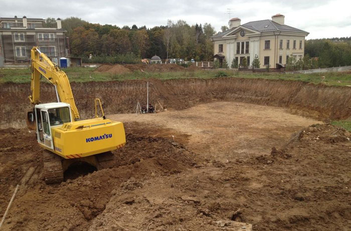
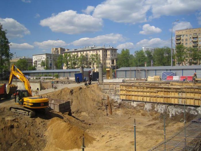
A rather complex technological process, including digging pits and strengthening slopes, characterized by phased implementation, is called the development of pits. Today these works are completely mechanized: excavators, bulldozers and other special equipment are used, piles are driven down to erect sheet piles, the fence itself is being carried out, etc.
The list of works included in the concept: excavation
Modern development of pits provides for the previous execution of some operations. It:
- geological exploration, on the basis of which the degree of density and composition of the soil, as well as the presence groundwater and the level of their occurrence; this information is necessary for calculating loads and choosing a method for driving piles;
- project development;
- coordination of documentation.
- digging a pit;
- providing waterproofing of the foundation (drainage);
- digging trenches;
- arrangement of embankments and slopes with sheet piling;
- distribution and removal of the excavated soil;
- laying of communication networks;
- backfilling of soil;
- vertical layout of the construction site;
- drilling and driving reinforced concrete piles or another method of driving them;
- foundation erection.
Earthen structures created during the excavation process can be temporary and permanent. Temporary include:
- foundation pit;
- trenches for laying communications;
- pit for excavated soil - cavalier.
The development of pits can be carried out at any time of the year, but in cold weather it is required to attract additional specialized equipment for loosening frozen soil, removing snowfall, etc.
The selection of equipment depends on climatic and local conditions, as well as on the condition of the soil. In cases where it is impossible to use classical earthmoving equipment, manual labor can also be used for excavation, supplemented by means of small mechanization.
In the developed project, all routes of underground and surface communications should be indicated. There is also a list of measures aimed at preserving nearby buildings and structures.
The excavated soil must be stored in such a way that it does not cause shedding of the slopes and walls of the pit. The tongue-and-groove fasteners are installed in such a way that they do not interfere with further work. In the case when the depth of the pit has exceeded the design mark, the excavated soil is laid on its bottom, which is rammed in layers.
Drilling, well construction and pile driving, as well as the construction of the foundation is carried out immediately after the completion of the excavation work. If an unplanned break occurs between these stages, then measures are taken to protect the pit from natural factors. For example, wellpoints or other equipment are installed to remove sediments.
The volume of work on the construction of the pit is 5-15% of the total construction volume of a particular facility. Moreover, their cost, including pile driving, can be up to 20%.
A well-designed construction site for the foundation of a building or structure guarantees the planned facility operational safety, reliability and durability. Such a task can only be done by highly qualified specialists who have an impressive experience of similar work, who have at their disposal all the necessary equipment and modern equipment... And all this is ready to provide your facility with Sotran, a construction and transport company, on account of which dozens of completed, successfully functioning facilities today.
The creation of a pit is the basis of any construction. It is with him that all work on the construction site begins. Its creation is based on an existing project.
The company "SpetsDemontazh" is ready to offer its customers services for the development of pits of any size and volume, while the initial cost of the work is from 300 rubles per cubic meter, including the process of removing the excavated soil to landfills. The final cost of the work is formed due to the selected work methodology and other factors of an individual nature.
Our company has significant experience in carrying out such work, uses modern equipment and technologies, which allows us to increase overall efficiency, reduce the time of work and their cost. We are guaranteed to provide daily processing of up to 1.5 cubic meters of land, including its cleaning from the construction site.
Among the factors that have a direct impact on the final cost of providing services for the development of a pit include:
- The nature of the terrain on which the work is planned.
- Features of the future foundation and the depth of its foundation.
- Soil type and moisture content. The presence or absence of groundwater.
- Terms of work and planned volumes.
- Seismological situation at the facility.
- The main hydraulic engineering parameters of the work and the features of the geology of the soil.
- Types of equipment used for construction.
- Distance to disposal sites.
The formation of the cost is carried out in each case individually, while in cottage construction the average cost of performing work varies between 300-400 rubles for each cubic meter of soil removed.
Despite the seeming simplicity, the process of developing foundation pits is not only laborious, but also technically complex work, the performance of which is better to be trusted by professionally trained people. Competent planning of the work allows not only to speed up the construction time of the facility, but also to adjust the cost estimate downward.
We are ready to offer our clients a full range of services related to the arrangement of foundation pits. We do:
- Layout on the ground
- Mechanized excavation of a foundation pit or trenches
- Loading into a cargo vehicle for the removal of soil from the construction site
- Direct disposal of soil to landfills
The company "SpetsDemontazh" uses exclusively mechanized methods of work, while for small volumes, compact mini-excavators with high performance are used. Used equipment brands JCB, Hitachi, Liebherr and others are among the best on the market. It is equipped with all the necessary set of attachments, which allows you to work with a depth of pits up to 19.5 meters inclusive.
Together with the sampling of soil, we organize on our own and its removal. This allows you to simplify and speed up the work process, reduce costs and eliminate the possibility of inconsistencies in the simultaneous work of several companies. In the process of removal, we use a three-shift scheme of work, which allows, if necessary, to dispose of up to 3 thousand cubic meters of soil every day.
Stages of excavation construction
Our specialists have sufficient practical experience in creating construction pits, which allows them to break down the work into several successive stages:
- At the first stage, geodetic exploration of the area is carried out, the composition and quality of the soil, the presence of soil waters are determined. Drawings of the future foundation pit are being drawn up.
- Excavation work is being carried out in accordance with the previously drawn up plan.
- The soil is loaded onto vehicles with its subsequent removal from the territory.
- A separate item is quality control of the work performed at all stages.
During the operation of the building, all structural loads are taken on by the foundation pit, therefore, at the stage of its arrangement, it is necessary to comply with the conditions prescribed in the plan.
The following factors directly influence the work on the creation of the pit:
- Soil properties. In this case, we mean its strength characteristics. For Moscow and the region most widespread obtained loamy soils or soils with a high level of peat content.
- The size of the future object. The future dimensions of the structure under construction form the loads that will affect the foundation pit, which requires the ability to hold them be foreseen in advance.
- Deepening the foundation. This factor is largely based on the height of the groundwater and the degree of soil freezing in winter conditions. Considered in the design process and the load on the foundation, taking into account the type of soil. For example, the deepening level for sandy and clayey soils is 0.5 and 0.7 meters, respectively.
- Climatic conditions at the time of work. In cases where work is carried out in winter, and the ground freezes from 0.25 meters or more, preliminary thawing is required. In the conditions of autumn or spring thaw, the work is complicated by the condition of the access roads and dirt roads at the sites of soil disposal, blurring directly at the construction site.
- The volume and composition of the preparatory work. This group includes clearing the area, transferring communications, reducing the height of the groundwater and so on.
MOSCOW ADVANCED DEVELOPMENT COMPLEX
MOSCOW GENERAL PLAN DEVELOPMENT DEPARTMENT
MOSSTROYLITSENZIYA
DEPARTMENTAL BUILDING STANDARDS
INSTRUCTIONS
FOR PRODUCTION OF LAND WORKS
IN HOUSING AND CIVIL
CONSTRUCTION CARRIED OUT
ORGANIZATIONS OF GLAVMOSSTROY
VSN 38-96
MOSCOW - 1997
Instructions for the production of earthworks in housing and civil construction, carried out by organizations of Glavmosstroy, were developed by the laboratory of bases and foundations of NIIMosstroy (Ph.D. V.A.Trushkov) and TsNIIOMTP (Ph.D. A.S. Menzurenko) at participation of Mosstroylicense (Yu.I. Stolyarov, Ph.D. V.D. Feldman). The instructions were drawn up on the basis of the results of research work carried out by NIIMosstroy, TsNIIOMTP, MGSU, as well as the many years of experience of specialized organizations of the Moscow Perspective Development Complex. The instructions were agreed with AO TSNIIOMTP, AO Glavmosstroy, AO Mosstroymehanizatsiya-2, AO Mosstroymehanizatsiya-5.
1. GENERAL PROVISIONS
1.1. These guidelines apply to the production and acceptance of excavation work carried out within quarters or separately under construction buildings, as part of zero cycle work, establish the sequence and interconnection of excavation work in summer and winter conditions, and recommend the most rational methods of work. 1.2. The instructions are intended for the design and organization of earthworks, as well as practical guidance in the performance of these works at housing and civil construction sites. 1.3. To carry out earthwork, the instructions contain technical characteristics of machines and mechanisms, the main operating parameters of earthmoving equipment and recommendations for their use in summer and winter. 1.4. When carrying out earthworks, the requirements of SNiP on the organization of construction production, geodetic works, safety measures and fire safety rules should be observed. 1.5. During earthworks, input, operational and acceptance control should be carried out, guided by the requirements of the relevant chapters of SNiP and reference annex 1 of SNiP 3.02.01-87. 1.6. Acceptance of earthworks with the preparation of inspection certificates hidden works should be carried out in accordance with provision 1 of SNiP 3.02.01-87. If necessary, it is allowed to indicate other elements in the project that are subject to intermediate acceptance with the preparation of certificates of inspection of hidden works.2. COMPOSITION OF EARTH WORKS
2.1. The structure of earthworks carried out in the complex of zero-cycle works within quarters or for separately constructed buildings includes: a) cutting, transportation and stacking of the vegetation layer of the soil (the places of storage of soil on the cartogram of earthworks are determined and applied by the construction organization); b) cutting and backfilling of soil during vertical planning of territories; c) digging trenches for the laying and re-laying of intra-quarter and courtyard underground communications - water supply, sewerage, gas pipeline, heating network, drains, collectors, drainage, electric cables and low-current lines; d) the device of an earthen trough and sandy base for permanent and temporary intra-quarter roads and driveways; e) digging pits and trenches for the foundations of buildings and structures with the removal of excess soil in the sinuses, trenches and compartments of technical underground with the delivery of the missing soil; f) backfilling and compaction of soil in the sinuses, trenches and compartments of technical subfields with the delivery of the missing soil; g) preparation of the base for the path of tower cranes.3. OBLIGATIONS OF THE ORGANIZATION DURING THE PRODUCTION OF EARTH WORKS
3.1. All earthworks (with the exception of the preparation of plant soil and peat) to be carried out by a mechanized method are required to carry out mechanization management under subcontracting agreements with organizations of foundation engineering trusts or organizations of general construction trusts. The complex of earthworks to be performed in a mechanized way by mechanization controls includes: a) preparatory work for all types of mechanized excavation. removal of the asphalt pavement and the breakdown of concrete and other foundations in a mechanized way at the places of excavation; b) when digging foundation pits for buildings; digging pits along the marks, as well as transporting soil; backfilling of soil under the floors of the technical underground (without compaction); backfilling of soil in the sinuses with compaction according to the technology recommended in section IV; arrangement and maintenance of temporary drainage ditches or enclosing rollers during earthworks (the construction organization indicates the place of water discharge); pumping storm and melt water during excavation; c) when digging for external communications: digging trenches into the dump with the removal of soil; backfilling of trenches with compaction according to the adopted technology and backfilling of trenches with sandy soil at intersections with roads, sidewalks and communications; d) for vertical planning: cutting off the soil according to the design marks (taking into account the necessary filling of plant soil) and moving it within a block, microdistrict or a separate site or outside them; delivery of missing soil for vertical planning; planning of territories according to design marks with tolerances up to ± 10 cm; e) for the production of landscaping works: cutting off plant soil and stacking it on temporary dumps. In winter, the collection of plant soil is not carried out; transfer of plant soil to organizations performing landscaping work, loading into vehicles and transporting it to places specified by landscaping organizations. 3.2. To ensure the normal organization of zero cycle works, including earthworks, the general contractor is obliged to transfer the site to the subcontractor foundation building trust no later than 1 month before the start of the work (Appendix 1). 3.3. The complex of earthworks is carried out under the direct control of the general contracting trust and the foundation building trust. To carry out earthworks in a mechanized way, they must, 20 days before the start of earthworks, send an order for the performance of work to the appropriate mechanization department with the following attachment technical documentation : a) for the development of pits and trenches - a working drawing of earthworks or a scheme for the production of earthworks with an indication of the dimensions of the pits or trenches at the base of the development and the vertical elevations of the base of the pits or trenches; b) for the production of work on a vertical layout: a draft of a vertical layout and a cartogram of earthworks with an indication of the boundaries of work, ensuring the commissioning of a group of buildings or individual objects; c) calculations of the volume of earthworks, compiled in accordance with the rules for calculating works, involved in the technical part of the Collection of unit prices for earthworks; d) calculation of the estimated cost or extract from the estimate, drawn up on the basis of the transferred schemes, calculations of the amount of work and unit prices for earthwork, taking into account the transition factors; e) a project for the production of earthworks with the obligatory indication of the movement of earth masses from pits, trenches and with vertical planning. In the event that, according to the project for the production of works, the soil is to be transported to an intermediate temporary warehouse, transfer the site for storing the soil to the mechanization department; f) a copy of the order for the development of pits and trenches. 3.4. The geodetic service associated with the performance of earthworks and, in particular, the breakdown of buildings in nature with the placement of axes for cast-off, the breakdown of the routes of external communications in nature, as well as the installation of the required number of benchmarks with the issuance of marks on them is assigned to the organization of general construction trusts and foundation construction trusts ... Organizations of foundation building trusts or general construction trusts should assist the mechanization departments of their geodetic service in monitoring the production of earthworks. Control over the observance of the specified marks during the development of pits and trenches and the responsibility for this lies with the mechanization department. Responsibility for the production of earthworks and the specified elevations on the vertical level lies with the Mechanization Department. 3.5. Responsibility for the implementation of excavation work in terms of dimensions at the base, as well as compliance with the steepness of the slopes established by the safety rules and technical conditions for the production of excavation work, lies with the Mechanization Department. 3.6. The organizations of foundation building trusts or general construction trusts are obliged to provide illumination of the territory on their own and at their own expense for the possibility of carrying out excavation work in two shifts, and also to ensure, if necessary, the performance of work to strengthen the slopes of the trenches. 3.7. Work on loosening frozen soil with the help of an explosion is carried out by specialized areas of blasting.4. SEQUENCE OF PERFORMANCE OF EARTH WORKS
4.1. When drawing up projects for the production of earthworks and performing these works in nature in summer conditions, it is necessary to observe the following sequence of their production: a) cutting, moving, stacking and removing vegetative soil from the construction site; b) the planning of the development areas, providing a temporary runoff of surface waters; c) digging trenches for laying underground utilities, including for the transfer of existing networks, the device of intra-quarter underground collectors from prefabricated elements and other underground structures; d) backfilling of soil into trenches with its compaction after laying pipelines and into the sinuses of underground collectors from prefabricated elements; e) digging soil in pits and trenches under underground part building; f) filling sand in the sinuses at the foundations and walls of technical underground and basements with its layer-by-layer compaction; g) preparation of the base for the path of tower cranes; h) vertical planning of the building area with soil compaction in the places of filling; i) earthworks for the arrangement of foundations for permanent roads, driveways and sites; j) earthworks for the improvement of the territory (plowing lawns, digging holes for trees and shrubs, etc.). Note ... The sequence of works specified in clause 4.1 depends on the specific conditions for building blocks (microdistricts) and, if justified, may change accordingly. 4.2. When performing zero cycle works in winter conditions, the order and sequence of earthworks change depending on the degree of their readiness, namely: a) if, by the beginning of winter, the cutting of the vegetation layer of the soil is completed at the construction site and the planning of the construction areas is completed to ensure the temporary runoff of surface water, then all types of earthworks listed in clause 4.1 are carried out in winter conditions in the same sequence, with the exception of work on the construction of foundations for permanent roads, driveways, sites, which are transferred to the warm season; b) if by the beginning of winter the zero cycle work has not been completed, then it is necessary to postpone the production of the largest possible volume of earthwork to the warm season. Exceptions to this instruction are allowed if it is necessary to cut a large layer of earth (over 1 m) on the site of the building and the site around it; c) in some cases, in winter conditions (with slightly interrupted terrain - up to 0.5 m), it is allowed to cut the soil for the construction of temporary roads, laying of crane runways and the construction of storage areas. 4.3. In order to prevent soil freezing, you should use the methods listed in table 1.|
Insulation method and time of work |
|
| 1. Plowing the soil to a depth of at least 35 cm, followed by harrowing to a depth of 10 - 15 cm. It is used in autumn to protect the soil from freezing in the case when digging of foundation pits is planned for the winter period. | |
| 2. Covering the soil surface with insulating materials - sawdust, mats, straw, etc. with a thickness of at least 10 cm. It is used in the fall to protect the soil from freezing if digging of foundation pits is planned for the winter period. |
|
| 3. Snow retention (installation of snow retention shields, construction of snow shafts with a thickness of at least 80 cm). It is used in winter to stop further freezing of the soil |
|
5. TECHNOLOGY OF PRODUCTION OF EARTH WORKS
5.1. Excavation projects are developed by the mechanization trusts performing these works. No later than one month before the commencement of earthworks, production projects must be considered and approved by the general contracting construction trust or foundation engineering trust. 5.2. The structure of the earthworks project should include: a) additional work performed with significant inflows of groundwater, swampy areas, possible landslides and ground displacements; b) methods of digging pits and trenches with a depth of more than 3 m or a complex configuration, requiring special fasteners; c) methods of preparing foundations for embankments and performing work when erecting embankments on collapsible soils, quicksands, wetlands and with inflows of groundwater; d) methods for arranging embankments on local heterogeneous soils that require special conditions for filling; e) ways to strengthen the slopes earthworks; f) calculations to justify the need to create possible dumps and open pits; g) methods of moving earth masses from pits, trenches and leveling faces. In addition to these basic provisions, the following measures should be developed in earthworks projects: a) methods for moving soil from reserve dumps for temporary storage, suitable for backfilling and dumping soil; b) methods of moving and transporting the missing sandy soil from other objects, indicating their addresses for backfilling under the base of floors, backfilling of trenches at their intersections with road surfaces, cables and underground utilities laid within the depth of the trenches. The same section should provide instructions on the composition of the excavation project, which should include: a) a working drawing or a scheme for the production of excavation with an indication of the dimensions of pits and trenches with their vertical marks along the base (bottom) of the excavations; b) calculations of the working and profile volume of earthworks in the vertical planning of the territory; c) calculations of the working and profile volume of earthworks for the laying of intra-quarter underground pipelines; d) calculations of the working volume of earthworks for the laying of intra-quarter underground cables; e) calculations of the working and profile volume of earthworks for the arrangement of troughs for intra-quarter roads, driveways, platforms and paths; f) calculations of the steepness of the slopes of pits and trenches with a depth of more than 5 m in all cases or up to 5 m in depth under unfavorable hydrogeological conditions. 5.3. Excavation works in the locations of existing underground communications are allowed only after taking measures to prevent damage to communications, with the written permission of the organization responsible for their operation, and in the presence of responsible representatives of construction organizations and the organization operating the underground communications. Prior to the commencement of earthworks, it is necessary to mark the axes and boundaries of these communications on the ground with well-visible signs. In case of discovery of existing underground communications and other structures that are not indicated in the existing design documentation, earthworks must be suspended, representatives of organizations operating these structures must be called to the site, at the same time the indicated places must be protected and other necessary measures must be taken to protect against damage found underground devices ... Digging of trenches and pits in the immediate vicinity of existing buildings and structures, as well as existing underground utilities, should be carried out only on condition that measures are taken against the settlement of these structures and the prior agreement of the customer with the organizations operating these buildings and structures. Measures to ensure the safety of existing buildings and structures should be developed as part of the work production project. When crossing trenches with existing underground utilities, the excavation of soil by a mechanized method is allowed at a distance of no closer than 2 m from the side wall and no closer than 1 m above the top of the cable pipe, etc. The soil remaining after mechanized mining must be refined manually without the use of percussion tools and with the adoption all measures to exclude the possibility of damage to these communications. 5.4. Excavation work is allowed only after the placement of markers. Securing the breakdown is carried out using outriggers and stakes located outside the earthen structures. The pillars defining elevation marks must be in the form of benchmarks. Layout of earthen structures should be carried out using geodetic instruments with careful observance of the design axes and elevations of the structure. When breaking up embankments, their subsequent settlement should be taken into account. 5.5. When building large residential areas (neighborhoods, microdistricts), earthworks should be carried out taking into account their complete completion within individual blocks of buildings. 5.6. Excavation work on cutting and transporting the vegetative layer of soil in blocks and on separately built-up areas must be carried out in compliance with the rules set out in 5.7 - 5.11. 5.7. Cutting of the vegetation layer of the soil should be performed only with bulldozers with a capacity of 60, 80, 100, 130 and 200 kW, depending on the maximum cutting depth. With an engine power of 60 kW, the maximum cutting depth should be 15 cm, with a power of 100 kW - 20 cm, with a power of 100 and 130 kW - 30 cm, with a power of 200 kW - over 30 cm. 5.8. The plant soil cut by bulldozers can be moved to the stacks at a distance of no more than 100 m. The soil is cut by successive longitudinal penetrations of the mechanism moving downhill in the working position. The passes must be equal to the length of the loading path of the machine. The movement of the mechanism in the working position uphill is allowed only with slopes not exceeding 3 - 5%. Unloading and leveling of plant soil in a stack begins from the remote part of the embankment. The collection of plant soil should be performed before the onset of frost and is not performed in winter. Stacks of vegetative soil should have entrances for transport with an angle of inclination to the horizon no more than 18 °. 5.9. It is recommended to take out the harvested plant soil from the stacking sites to the places of its consumption by dump trucks with a carrying capacity of over 3.5 tons. The plant soil should be loaded into dump trucks with single-bucket excavators with a bucket with a capacity of 0.25 - 0.65 cubic meters. m. 5.10. When cutting, transporting and stacking, it is forbidden to mix plant soil with soil unsuitable for planting and sowing. The quality and suitability of the plant soil for landscaping is determined by a competent soil-agronomic laboratory. 5.11. The use of plant soil suitable for landscaping works for other purposes is prohibited. 5.12. Excavation works on the vertical planning of the built-up areas must be carried out in compliance with the rules set out in sections 5.14 - 5.32 of these Instructions. Performing work on the vertical planning of built-up areas, as well as special sites for stadiums, squares, boulevards, etc. allowed only if there are planning projects for all types of underground structures and general ground balance. 5.13. The vertical planning of the territory of quarters or separately under construction buildings should be carried out: a) with a depth of cut of the soil of more than 0.5 m or a distance of its movement no more than 100 m - by bulldozers with a power of 60 to 200 kW or scrapers with a bucket with a capacity of 6 cubic meters m and more; b) when the depth of cut of the soil is more than 0.5 m or the distance of its movement is more than 100 m (with the depth of cut is less than 0.5 m), as well as if there are permanent or variable roads laid on the planned territory or prepared troughs for the foundations of roads, sites and tracks - single-bucket excavators with a bucket with a capacity of 0.5 - 1.0 cubic meters. m with the movement of soil by dump trucks. 5.14. When carrying out earthworks on the vertical planning of the territory, the Mosstroymehanizatsiya trusts are given the right to choose brands and types of machines and mechanisms, depending on the working conditions, soil categories and the availability of machines in mechanization departments. 5.15. Planning works on sites with cutting and backfilling are carried out using bulldozers or scrapers according to the scheme shown in Fig. 1. 5.16. The vertical leveling of the territory using single-bucket excavators is carried out according to the schemes shown in Fig. 2 and 3. In fig. 2 shows the sequence of soil cutting by a single-bucket excavator with a front shovel (bucket capacity 0.5 - 1.0 cubic meters) with dump trucks driving into the face, and in Fig. 3-single-bucket excavator with a backhoe (bucket capacity 0.5 - 1.0 cubic meters) without dump trucks entering the face. The main parameters of single-bucket excavators are shown in Appendix 2. 5.17. Excavation works are carried out in accordance with SNiP III -4-80 "Safety in construction" and "Guidelines for safety when excavating soil with excavators." 5.18. For the development of frozen soils when planning territories in winter conditions, one-bucket excavators with a backhoe with a bucket capacity of 0.5 - 1.0 cubic meters should be used. m. With a freezing depth of up to 0.25 m, the soil is developed by excavators without preliminary preparation, and at a great depth of freezing, the mechanisms and methods for preparing frozen soil for excavation are recommended, given in table. 2.
Figure: 1. The scheme of movement of the bulldozer when planning the territory
Figure: 2. Diagram of soil development using a single-bucket excavator with a front shovel
Figure: 3. Diagram of soil development using a single-bucket excavator with a backhoe
More detailed recommendations are given in the "Guidelines for the development of frozen soils by machines and mechanisms". 5.19. In cases where the machines recommended for loosening frozen soil cannot be used in construction, the soil should be thawed using heating elements. Achievable thawing depth of heating elements is not more than 1.5 m. 5.20. When preparing the soil for excavation with a wedge-hammer or an explosion, measures must be taken to ensure the integrity of buildings, structures, communications and work safety located near buildings (warning notices are posted, windows of neighboring buildings are protected, a dangerous zone is defined, etc.). 5.21. Loosening of frozen soil with a RO-126 mounted ripper on the basis of the DET-250 tractor is carried out by parallel penetrations in layers to a depth of 0.4 m with each penetration with subsequent transverse penetrations at an angle of 60 - 90 ° to the first. 5.22. No earlier than two hours before the development of the soil, it is necessary to clear the area intended for planning from snow. 5.23. For the development of frozen ground, bucket wheel excavators ETR-223B, ETR-224A are equipped with hydraulic reducers. 5.24. Rotary excavators ETR-223B, ETR-224A when digging frozen soil cut parallel trenches, and the ridges remaining between them are developed by excavators equipped with backhoes with a capacity of 0.5 cubic meters. m and above. 5.25. To prevent the soil from freezing, after excavation by rotary excavators, the trenches are again filled up with the help of a bulldozer with discarded soil. 5.26. Loosening of frozen soil by an explosion is carried out in the absence of buildings, structures and communications near the developed array. This work should be performed by specialized blasting areas of mechanization departments. 5.27. The deviations of the marks during the vertical planning of the territory should not exceed: when cutting the soil with bulldozers ± 5 cm; when cutting soil with scrapers ± 10 cm; when filling soil with bulldozers or scrapers, taking into account the compensating layer for soil settlement ± 5 cm. 5.28. Cleaning of the planned area after cutting the soil with excavators should be carried out by bulldozers, with the exception of areas closed by roads and sidewalks that can be damaged by bulldozer tracks. 5.29. Dumping of soil during the planning of the territory should be carried out in layers, the thickness of which is determined by the project for the production of earthworks and is assigned depending on the method of soil compaction. Laying of soils is carried out in horizontal or slightly sloping layers. The planned surfaces of the territory should have a slope for water flow not less than 0.002 or not more than 0.005 towards the water outlet. 5.30. When planning territories in order to comply with the marks and slopes specified by the project, all bulk soil under the road bases and sites must be compacted. Under the green areas, the soil is subject to compaction when the thickness of the dump is more than 1 m. 5.31. The required degree of soil compaction is achieved by the appropriate number of passes of the load compacting machines and the observance of the thickness of the filled soil in the layer-by-layer backfill in accordance with the data in Table. 3.
Table 3
Standards for compaction of bulk soils
|
Types of skating rinks |
Number of passes in one place |
The greatest thickness of the soil layer in the layer-by-layer backfill, cm |
| Pneumatic wheels weighing 10 t | ||
| Pneumatic wheels weighing 25 t | ||
| Cam type D-130 weighing up to 5 t | ||
| Cam type D-220 weighing up to 30 t | ||
| Tamping plate on a 2 ton excavator | ||
| Self-propelled pneumatic roller weighing 40 t |
Figure: 4. Diagram of digging a pit by excavators with a backhoe during its zigzag movement along the day surface of the site (the digits indicate the sequence of movement of the excavator)
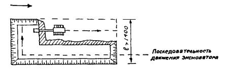
Figure: 5. Diagram of excavation of a pit by an excavator with a backhoe when it moves in parallel moves along the day surface of the site
5.38. When digging pits, it is necessary to simultaneously carry out all the excavation work provided for by the excavation project, in particular, the arrangement of ramps for the entry and exit of excavators, piles and bulldozers, the arrangement of widening and recesses for placing piles, water-reducing installations and other mechanisms. 5.39. The soil excavated from the pits is transported on dump trucks of the objects under construction to the places: a) filling up the soil, provided for by the cartogram of the vertical layout of the territory; b) city dump - if the soil is unsuitable for bedding and backfilling; c) backfilling of sinuses, trenches and other objects (this or another quarter); d) reserve dumps - for temporary storage of suitable soil in the amount necessary for backfilling or backfilling during construction. Notes: 1. It is prohibited to leave or temporarily store the soil directly behind the upper edge of the excavations (within the collapse prism) or at the bottom of the finished excavation. 2. The unsuitability of the soil for backfilling, backfilling and embankments is established by acts with the participation of the customer when opening pits, trenches and leveling faces. 5.40. In soils of natural moisture in the absence of groundwater and nearby underground structures, excavation of pits and trenches with vertical walls without fasteners can be carried out to a depth (in m) not more than: 1.0 - in sandy gravelly soils; 1.25 - in sandy loam; 1.50 - in loams and clays; 2.0 - in especially dense rocky soils. Notes: 1. In the presence of bulk, loose and medium density sandy and gravelly soils of natural moisture, as well as when located within the prism of the collapse of any structures or communications, digging pits with vertical walls without fasteners is not allowed and is carried out taking into account the device necessary fasteners or slopes. 2. It is not allowed to dig ditches and trenches with vertical walls without fastenings in the presence of waterlogged bulk and sandy soils. 5.41. The greatest steepness of the slopes of trenches and pits, arranged without fastenings in homogeneous continental cohesive soils of natural moisture, should be assigned in accordance with Table 4.
Table 4
The greatest permissible steepness of slopes of trenches and pits
|
Types of soils and their condition |
Excavation depth, m |
|||||
|
angle to degrees |
slope steepness |
angle to degrees |
slope steepness |
angle to degrees |
slope steepness |
|
| Bulk | ||||||
| Sandy and gravelly wet (unsaturated) | ||||||
| Clay: | ||||||
| Sandy loam | ||||||
| Loam | ||||||
| Clay | ||||||
| Loess dry | ||||||
Table 5
The smallest permissible horizontal distance from the base of the cut slope to the nearest machine supports
|
Digging depth |
Bulk soil |
||||
|
sandy and gravel |
sandy loam |
loamy |
clayey |
dry loess |
|
|
horizontal distance of the foot of the slope to the nearest support, m |
|||||
Table 6
Permissible underflow of soil (cm) at the base when operating with single-bucket excavators
5.49. Single-bucket excavators equipped with a backhoe with a bucket with a capacity of 0.5 - 1.5 cubic meters should be used for the development of frozen soils of pits in winter conditions. m 5.50. Instructions for preparing for excavation of frozen soil, given in paragraphs. 5.18 - 5.26, fully apply to the development of soil in pits. 5.51. In order to avoid subsidence of the soil in the filled up sinuses between the slopes of the pits and the walls of the technical subfields, it is necessary to carefully compact it and not allow the use of frozen soil for filling. 5.52. Pits for the foundations of walls and underground structures must be dug without disturbing the natural structure of the soil at the base. When excavating with multi-bucket excavators and scrapers, the shortfall during excavation development should not exceed 5 cm. Development of soil shortages, as a rule, must be performed mechanically. When cleaning up shortfalls for pits with bulldozers, excavators with special cleaning buckets or other leveling machines, the remaining shortfall to the design mark should not exceed 5 - 7 cm, which is manually finalized in the places where the foundation is installed. Accidental digging of soil, allowed during excavation of foundation pits, must be filled with soil that is homogeneous with the soil being developed in the excavation, brought to its natural density. In critical cases, the search points are filled lean concrete... 5.53. Excavation work for digging trenches for laying intra-quarter underground utilities must be carried out in compliance with the rules set out in paragraphs. 5.54 - 5.84 of these Instructions. 5.54. Digging trenches for laying intra-quarter underground utilities should be carried out with machines recommended in Table. 7.Table 7
|
Soil characteristics |
Trench depth in m |
|||||
|
from 1.5 to 2.0 m |
over 2.0 m |
|||||
|
sloped trenches |
trenches with vertical walls |
sloped trenches |
trenches with vertical walls |
sloped trenches |
||
| Lungs: | ||||||
| vegetable soil, sand, loam, no impurities, sandy loam without impurities, non-caking slag | ETR-223B ETR-224A | ETTs-252M | EO-3323A EO-3131 | ETTs-252M | EO-3323A EO-4121A | |
| Average: | ||||||
| oily clay, heavy loam, sandy loam with crushed stone, crushed stone with a grain size of up to 10 mm | ETR-223B ETR-224A | EO-2626VZ EO-3323A EO-3131 | ETR-224A | EO-3323A EO-3131 | ETTs-252M | EO-3323A EO-4121A EO-4112 |
| Severe: | ||||||
| pebbles and gravel, hard clay, sand with crushed stone more than 40%, crushed stone with a grain size of up to 50 mm, construction waste | ETR-223B ETR-224A | EO-3323A EO-3131 EO-4112 EO-4121A | ETR-224A | EO-4112 EO-4121A | ETTs-252M | EO-4121A EO-4112 EO-5111 |
Table 8
|
Types of soils and their condition |
Excavation depth, m |
Types of fasteners |
| Soils bound (clay, loam and sandy loam) of natural moisture | Horizontal fastening with boards with gaps through one board | |
| Bulk soils (sands) of natural moisture | Solid vertical and horizontal mount | |
| Different soils and high humidity | Also | |
| All types of soils with a strong inflow of groundwater |
regardless of depth |
Sheet piling below the groundwater level with a bivvy to a depth of at least 0.75 m |
Table 9
Pit sizes
|
Butt joint |
Sealant |
Conditional passage of the pipeline, mm |
Pit sizes, m |
|||
| Steel | Welded | For all diameters | ||||
| Cast iron | Bell | Rubber cuff | Up to 300 incl. | |||
| Hemp strand | Up to 300 incl. | |||||
| St. 300 | ||||||
| Sealants | Up to 300 incl. | |||||
| St. 300 | ||||||
| Asbestos-cement | Coupling type CAM | Shaped rubber ring | Up to 300 incl. | |||
| St. 300 | ||||||
| Cast iron flange coupling | O-ring and KChM type | Up to 300 incl. | ||||
| St. 300 | ||||||
| Any for free-flow pipes | Any | Up to 400 incl. | ||||
| Concrete and reinforced concrete | Socket, coupling and with a concrete belt | O-ring rubber | Up to 600 incl. | |||
| 600 to 3500 | ||||||
| Plastic | All types of butt joints | For all diameters | ||||
| Ceramic | Bell | Asphalt bitumen, sealant, etc. | Also | |||
Table 10
The smallest width of trenches with vertical walls along the bottom for laying pipelines
|
Methods of laying pipelines |
Trench width, m, excluding fasteners for butt joint |
||
|
bell |
socket, flanged, seam for all pipes and socket for ceramic pipes |
||
| 1. In lashes or separate sections with the outer diameter of pipes, D, m: | |||
| up to 0.7 incl. |
D +0.3, but not less than 0.7 |
||
| St. 0.7 | |||
| 2. The same in the areas developed by trench excavators for pipelines with a diameter of up to 219 mm, laid without lowering people into trenches (narrow trench method) | |||
| 3. The same in pipeline sections loaded with reinforced concrete weights or anchor devices | |||
| 4. The same in sections of the pipeline loaded with non-woven synthetic materials | |||
| 5. Separate pipes with outer pipe diameter D, m, incl .: | |||
| up to 0.5 | |||
| from 0.5 to 1.6 | |||
| from 1.6 to 3.5 | |||
Table 11
Estimated thickness of the sandy underlying layer of the permanent road under load N-13
After planning, the sandy base is compacted with an I-7 vibrator. The construction of a sandy base during snowfall and on frozen ground is not allowed. 5.89. When digging troughs for intra-quarter roads, driveways, platforms and paths, use single-bucket excavators equipped with a backhoe with a bucket with a capacity of 0.25 - 0.65 cubic meters. m bulldozers with a capacity of 80 to 200 kW, dump trucks with a carrying capacity of over 3.5 tons. 5.90. In winter, the ZMF-2300 and 2300A earthmoving and milling machine should be used to build troughs for roads. 5.91. When leveling the roadbed for roads and driveways, deviations from the design marks should not exceed +5 cm. 5.92. Excavation work on the construction of the subgrade for crane runways must be carried out in compliance with paragraphs. 5.93 - 5.103 of these Instructions. 5.93. The roadbed in the track laying area must be cleared of building materials waste, ice, snow, foreign objects and vegetation layer of the soil. Before starting the construction of the subgrade in the area of \u200b\u200bthe rail track, all excavation work related to the construction of the foundation of the building and the laying of underground communications must be completed. 5.94. The subgrade area should be planned in a transverse direction with a single-slope profile, with a slope towards the drain from 0.008 to 0.01. The longitudinal slope of the subgrade should be no more than 0.003. The width of the subgrade for a rail track constructed near a building should be taken depending on the type of cranes and determined by the formula:B \u003d A + 3h b + S + 2 (200 + 400) mm,
Where A - track track, mm; h b - the required thickness of the ballast under the supporting elements, mm; S - size support element across the track, mm. The initial data for determining the width of the roadbed are given in Appendix 1 of SNiP 3.08.01-85. 5.95. It is allowed to arrange the subgrade for the rail track entirely from bulk soil, as well as arrange part of the subgrade on bulk soil, and the other part on the main soil with a slope of 1: 1.5 slope at the junction of the bulk soil to the main one; the fill soil should be either sandy or homogeneous with the main soil. 5.96. When constructing a subgrade from bulk soil, it is prohibited: a) to use soil mixed with construction waste, wood residues, rotting or swelling inclusions, ice, snow and turf; b) use non-draining soil (clay, loam), mixed with drainage, in order to avoid the appearance of water bags in the body of the embankment; c) cover a layer of soil with high drainage capacity with soil with less drainage capacity; d) lay frozen soil, as well as thawed, mixed with frozen; e) carry out work on the construction of the roadbed during an intense snowfall without applying measures to protect the bulk soil from snow inclusions; f) to compact the soil with watering in winter. When resuming work after snowfalls and blizzards, the surface of the track to be arranged must be cleared of snow and ice. 5.97. The fill soil of the subgrade should be laid in layers with compulsory layer-by-layer compaction. The thickness of the layers is determined by the machines and equipment used to compact the soil. The density (volumetric weight of the skeleton) of the subgrade soil in g / m 3 should be at least: for fine and dusty sands - 1.7 for sandy loams and loams - 1.65 for heavy loams - 1.55 for dusty loams and for clays - 1.5. It is allowed to compact the bulk sandy and sandy loam soils of the subgrade in the summer by irrigation with a spray jet of water of each dumped layer of soil. The density of the subgrade soil should be checked according to GOST 5182-78 or any other modern methods under both rail lines. When constructing tracks with wooden half-sleepers, the density of the soil should be checked at least every 12.5 m, and when constructing tracks with reinforced concrete beams - under each beam. The results of the check must be entered into the act of putting the rail track into operation. 5.98. If the required soil density is less than the values \u200b\u200bspecified in clause 5.97, it must be re-compacted. If the required soil density is not achieved during the compaction process, the preparation of the subgrade should be carried out according to a special project. 5.99. Compaction of the subgrade should be performed when the natural moisture content of the soil is optimal. The optimum soil moisture content is shown in Table 12.
Table 12
The natural soil moisture should be determined according to GOST 5180-84. If the natural moisture content of the subgrade soil exceeds the optimum, before compaction it is necessary to remove the upper waterlogged soil layer. 5.100. Backfilling and compaction of trenches, sinuses and pits, over which rail tracks are to be built, should be carried out in the same way as the foundation of filled soil. 5.101. In winter conditions, it is allowed to use frozen soil for embankments and backfilling of sinuses, over which crane runways will be built. When laying frozen soil, layer-by-layer filling with a thickness of no more than 0.2 m with careful compaction should be observed. The size of clods of soil should not exceed 0.1 m. 5.102. A ballast prism is laid on the prepared subgrade in accordance with the instructions of SNiP 3.08.01.85. 5.103. When preparing the subgrade for laying rail tracks, the following mechanisms should be used: - a mounted excavator with a bucket with a capacity of 0.25 m 3 on a pneumatic-wheeled tractor of 1.4 t class; - a bulldozer on a caterpillar tractor of class 3 - 10 tons, depending on the maximum cut of the soil; - trailed vibrating rollers weighing 4 - 9 tons; - dump trucks with a carrying capacity of 3.5 - 10 tons; - single-bucket loaders on caterpillar or pneumatic wheels with a carrying capacity of 2 - 3 tons; - motor grader up to 110 hp Notes: 1. In connection with a wide range of machines of various standard sizes, models and their modifications, as well as a large range of replaceable attachments for these machines, the range of earth-moving equipment included mainly models of machines produced domestic industry during 1990 - 1996 These models will be in operation for several years (Appendices 3 - 11). 2. When performing earthwork, foreign earthmoving machines can be used, which, in terms of their technological parameters, correspond to the scope of work and the conditions for their implementation. The range of foreign machines and their parameters can be obtained from separate reference catalogs. It is not possible to provide such information within the framework of this work due to its limited volume. 3. Special works (punctures under roads, blasting operations, wall in the ground, soil consolidation, etc.) were not reflected in the framework of these instructions, since these types of work require special justifications in the design documentation for their implementation.Attachment 1
Appendix 2
BASIC PARAMETERS OF SINGLE BUCKET EXCAVATORS
A) - equipped with a straight shovel; b) - equipped with a backhoe; c) - equipped with a dragline; R is the largest digging radius in m; R 1 - the largest unloading radius in m; Н 1 - maximum digging height in m; H 2 - the highest unloading height in m; H 3 - maximum digging depth in m; Н 4 - the highest unloading height in m; L is the length of the main boom in m; R 2 - the largest unloading radius in m; H 5 - unloading height in m; H 6 - digging depth with side pass in m; H 7 - digging depth at the end pass in m.
Appendix 3
Technical Specifications of Trench Chain Excavators
|
The name of indicators |
||||
| Base |
MTZ-82 with dozer blade |
MTZ-82 with dozer blade |
Tractor TT-4 |
Tractor T-170M.00-1 |
| Engine power, kW | ||||
| Weight, t |
19.5, with add. equipment 20.6 |
|||
| Trench dimensions, m: | ||||
| depth | ||||
| width |
2.8 at the top 0.8 - 1.0 at the bottom |
|||
| Working speed, m / h | ||||
| Transport speed, km / h | ||||
| Dozer blade width, mm | ||||
| Blade height, mm | ||||
| Dump depth, m | ||||
| Blade rotation angle, degrees | ||||
| Optional equipment | Asphalt cutter, bar tool, trench cutting chain kit | Bar equipment for cutting cracks in permafrost, asphalt up to 1.4 m deep | With add. equipment, trench depth 3.5 m | Bar tool, trench cutting chain kit |
Appendix 4
Technical characteristics of trench bucket wheel excavators
|
The name of indicators |
||
| Base | Tractor using the units of the tracked tractor T-170 | |
| Engine power, kW | ||
| Weight, t | ||
| Trench dimensions, m: | ||
| depth | ||
| width without slopes | ||
| with slopes along the top | ||
| Working speed, m / h | ||
| Transport speed, km / h | ||
| Rotor: | ||
| diameter, mm | ||
| number of buckets | ||
| bucket capacity, l | ||
| Cutting speed, m / s | ||
| Conveyor belt width, mm | ||
| Belt speed, m / s |
Appendix 5
Technical characteristics of single-bucket universal excavators with a bucket with a capacity of up to 0.2 m 3
|
The name of indicators |
Borex-1621 |
Borex-1623 |
||
| Base |
Tractor T-25 |
Tractor T-30 |
Backhoe loader |
|
| Appointment | For earthwork in soils I - III cat. | For excavation in soils I - V cat. and loading and unloading operations in cramped conditions | For excavation in soils I - IV cat. and loading and unloading works | |
| Bucket capacity, m 3 | ||||
| Engine power, kW | ||||
| Weight, t | ||||
| Maximum digging depth with a backhoe, m | ||||
| Angle of rotation of the working equipment in the plan, deg. | ||||
| The greatest effort of digging, kN | ||||
| Digging axis offset, m | ||||
| Travel speed, km / h | ||||
| Optional equipment |
burial bucket 0.25 m 3 |
burial bucket 0.25 m 3 |
burial bucket 0.86 m 3 |
Appendix 6
Technical characteristics of semi-revolving hydraulic excavators with a bucket with a capacity of 0.25 m 3 for earthwork in soils of I-IV categories, as well as loading and unloading operations
|
The name of indicators |
Borex-2628 |
|||
| Base | ||||
| Bucket capacity, m 3 | ||||
| Engine power, kW | ||||
| Weight, t | ||||
| Hydraulic system pressure, MPa | ||||
| Maximum unloading height, m | ||||
| Travel speed, km / h | ||||
| Optional equipment | Shovel, back shovel, grab, forks, hydraulic hammer, dozer blade, ripper tooth, grab, replaceable buckets, telescopic stick | Loading. bucket 0.83 m 3, back and front shovels, grab, hydraulic hammer, grapple, ripper tooth, replaceable buckets | Loading. bucket 0.5 m 3, back and front shovels, grab, hydraulic hammer, gripper, ripper tooth, replaceable buckets | Loading, bucket 0.5 m 3, backhoe, grab, suspension hook, grab, hydraulic hammer, replacement buckets |
Appendix 7
Technical characteristics of hydraulic single-bucket excavators for the development of non-frozen soils of I-IV categories and previously loosened frozen and rocky soils with inclusions not exceeding 200 mm, as well as for loading and unloading operations
|
The name of indicators |
||||
| Base | Tractor-type crawler | Pneumatic wheel travel | Crawler | KAMAZ-5531 chassis |
| Bucket capacity, m 3 | ||||
| Engine power, kW | ||||
| Weight, t | ||||
| Hydraulic system pressure, MPa | ||||
| Digging depth, m | ||||
| Maximum unloading height, m | ||||
| Largest digging radius, m | ||||
| Travel speed, km / h | ||||
| Replaceable working equipment | Backhoe with buckets, m 3: 0.25; 0.4; 0.5; 0.63; 0.8; loading, bucket 1.4 m 3, front shovel, grab, ripper tooth, hydraulic hammer | Backhoe with buckets, m 3: 0.25; 0.4; 0.5; 0.63; 0.8; loading bucket 1.4 m 3, front shovel, grab, ripper tooth, hydraulic hammer | Ex. buckets 0.15; 0.25; 0.5; 0.63 m 3, leveling and profile buckets 0.5 m 3, leveling blade 2 m wide, ripper, add. insert 1.2 m | Telescope. boom 3.2 m, buckets 0.25; 0.5; 0.63 m 3, profile 0.63 m 3, grading 0.5 m 3, extension, single-shank ripper, blade |
Appendix 8
Technical characteristics of single-bucket excavators for excavation in soils of I-IV categories and previously loosened rocky and frozen soils with inclusions not exceeding 400 mm in size, as well as for loading and unloading operations
|
The name of indicators |
||||
| Base |
Crawler |
Pneumatic wheel travel |
Crawler |
|
| Working equipment drive |
Cable |
Hydraulic |
Hydraulic |
Cable |
| Bucket capacity, m 3 | ||||
| Engine power, kW | ||||
| Weight, t | ||||
| Hydraulic pressure MPa | ||||
| Largest digging radius, m | ||||
| Digging depth, m | ||||
| Digging height, m | ||||
| Maximum unloading height, m | ||||
| Largest unloading radius, m | ||||
| Travel speed, km / h | ||||
| Replaceable equipment | Forward and reverse shovels, dragline, grab, crane, piling equipment | Backhoe, grab, hydraulic hammer, ripper tooth, buckets for various purposes | Front and back shovels, grab, hydraulic hammer, ripper, drilling equipment, hook suspension | Forward and backward shovels, dragline, grab, crane |
Appendix 9
Types of single-bucket excavators used for excavation of excavations
|
Characteristics of soils |
Pit depth up to 2 m |
Pit depth up to 4 m |
Pit depth up to 6 m |
Water-saturated soils at a pit depth |
||||
|
with a volume of soil removed up to 1.5 thousand cubic meters. m |
with a volume of soil removed over 1.5 thousand cubic meters. m |
with a volume of soil removed up to 4 thousand cubic meters. m |
with a volume of soil removed over 4 thousand cubic meters. m |
with a volume of soil removed up to 6 thousand cubic meters. m |
with a volume of soil removed over 6 thousand cubic meters. m |
|||
| Light vegetable, sand and sandy loam without admixtures, non-caking slag | EO-2226 EO-3323A | EO-3323A EO-3131 | EO-3323A EO-3131 | EO-3123 EO-4112 EO-4121A | EO-4112 EO-4121A | EO-5111 EO-5222 | EO-4112 dragline | EO-4112 dragline |
| Medium Oily clay, heavy loam, sandy loam with crushed stone, crushed stone with a grain size of up to 40 mm | EO-3131 EO-3323A | EO-3223A EO-3131 | EO-4121A EO-4112 | EO-4121A EO-4112 | EO-4121A EO-4112 | EO-5111 EO-5222 | EO-4112 dragline | EO-4112 dragline |
| Heavy pebbles and gravel, hard clay, sand with more than 40% crushed stone, construction waste, crushed stone with a grain size of up to 50 mm | EO-4121A EO-4112 | EO-5111 EO-5122 | EO-5111 EO-5122 | EO-5111 EO-5122 | EO-5111 EO-5122 | EO-5111 EO-5122 | EO-5111 dragline | EO-5111 dragline |
Appendix 10
Technical characteristics of bulldozers
|
The name of indicators |
|||||
| Base | DT-75P-P2 DT-75DR-S2 | DZ-190 | T-170.01 | DET-250M2 | T-500 |
| power, kWt | |||||
| Weight, kg | |||||
| Dump |
non-rotation. |
non-rotation. |
|||
| Overall dimensions, mm: | |||||
| length | |||||
| height | |||||
| Cutting angle, degrees | |||||
| Rise, mm | |||||
| Lowering, mm | |||||
| Travel speed, km / h |
Appendix 11
Technical characteristics of loosening equipment mounted on crawler tractors
|
The name of indicators |
|||||
| Tractor types | DT-75D-RS2 DT-75N-RS2 | T-170.00 T-170.01 T-170M.00 T-170M.01 | DET-250M2 DET-250M3 | T-330 | T-500 |
| Traction class of tractors | |||||
| Number of teeth | |||||
| Depth, mm | |||||
| Capture width, mm | |||||
| Weight, kg |
Appendix 12
Technical specifications earthmoving and milling machine ZMF-2300
| 1. General Provisions. 1 2. Composition of earthworks. 2 3. Obligations of the organization in the course of earthworks. 2 4. The sequence of earthworks. 3 5. Technology of earthworks production. 4 Appendix 1 Act of transferring the site for the production of zero cycle works. 19 Appendix 2 Basic parameters of single-bucket excavators. 19 Appendix 3 Technical characteristics of trench chain excavators. 20 Appendix 4 Technical characteristics of trench bucket wheel excavators. 20 Appendix 5 Technical characteristics of single-bucket universal excavators with a bucket with a capacity of up to 0.2 m 3 21 Appendix 6 Technical characteristics of part-turn hydraulic excavators with a bucket with a capacity of 0.25 m 3 for excavation in soils of I-IV categories, as well as loading and unloading operations. 21 Appendix 7 Technical characteristics of hydraulic single-bucket excavators for the development of non-frozen soils of I-IV categories and previously loosened frozen and rocky soils with inclusions not exceeding 200 mm, as well as for loading and unloading operations. 22 Appendix 8 Technical characteristics of single-bucket excavators for excavation in soils of I-IV categories and previously loosened rocky and frozen soils with inclusions not exceeding 400 mm in size, as well as for loading and unloading operations. 22 Appendix 9 Types of single-bucket excavators used for excavation of excavations. 24 Appendix 10 Technical characteristics of bulldozers. 25 Appendix 11 Technical characteristics of loosening equipment mounted on tracked tractors .. 25 Appendix 12 Technical characteristics of the ZMF-2300 earthmoving and milling machine. 25 |
We carry out the development of the pit and perform any work of the preliminary stage of construction in Moscow and in other regions of Russia.
A pit is a specially dug hole for laying a foundation or for setting up an underground structure. Its configuration, depth and other parameters depend on the following factors:
- type, dimensions, weight of the future building;
- type of foundation - tape, pile, etc.;
- type of soil;
- groundwater level;
- freezing level;
- seismic situation in the area of \u200b\u200bdevelopment;
- presence / absence of other structures and communications nearby.
You can order work on the development of the pit in our company
Prices for zero cycle work and equipment transfer are the lowest in the region. For all questions call: 8 800 707-72-09
Technological map for the development of the pit
Since the beginning of the development of the foundation pit, our company has been taking a number of measures to reduce the possible risks of erecting building structures:
- geological / hydrogeological research;
- dewatering measures (on fine-grained soils with high groundwater levels);
Preliminary research
Before proceeding with the design of a structure, our specialists must find out the conditions in which it will be erected and function. The first thing that is carried out at the stage of preparation for construction is geological studies of the site.
We adhere to the following work plan:
- Study of archival documents in the area. Data on tectonics, layered structure of the soil, seismic conditions. All engineering and geological information that is available.
- Field stage. Acquaintance with the site on site: study of the relief, geophysical methods, excavation / drilling of exploration wells. Sampling of soil samples. At this stage, the sequence and thickness of the layers, as well as the level of the groundwater location, are specified.
- Cameral stage. Soil samples (composition, physicochemical characteristics) and water samples (chemical composition) are studied in a laboratory way.
If construction is planned on a watered area or in coastal zone, hydrogeological studies are also carried out.
We have our own geological prospecting specialists and hydrogeologists, we have all the necessary equipment for field work (drilling rigs, etc.) and equipment for laboratory research.
The main stages of excavation development
The development of a foundation pit is carried out in the following order:
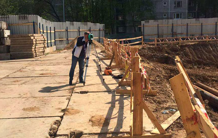
- Geodetic stakeout: parameters and angles of the pit are measured. The markup is carried out using levels and theodolites. Trenches are being made around the perimeter of the future pit. The cast-off is made from posts and boards, cords are pulled between the posts. The cast-off marks the boundaries of the pit and the future structure.
- Excavation work. First, the sod (vegetative layer of soil) is removed, then a foundation pit is dug to the design depth. The steepness of the slopes is calculated in the project and depends on the characteristics of the soil.
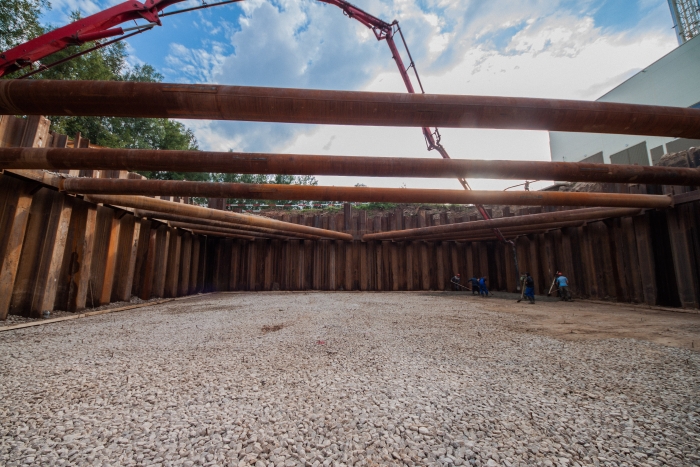
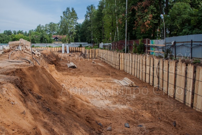
- Slope processing. The goal is to protect the walls from shedding, and the foundation pit itself from the penetration of groundwater.
We reinforce the slopes with metal sheet piles.
Other options - bituminization, freezing - are more energy intensive and less efficient.
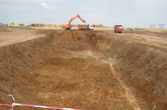
- The entire volume of soil during excavation is divided into parts. The bulk is taken out of the site, some remains for filling the sinuses of the excavation at the end of the foundation pouring.
We carry out the development of the pit in accordance with GOST and building rules (45.13330.2012 SP, latest revision 3.02.01-87 SNiP), and also draw up all the necessary accompanying documentation.
Methods for developing a pit and the necessary equipment
There are 4 methods of developing a pit in a mechanized way:
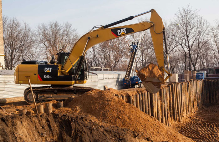
- mechanical - excavation with excavators;
- hydromechanical - washing out with powerful water jets. It is used for buildings near water sources. At the first stage, the soil is eroded, then the water-soil mass is transferred to the dump and the water is separated;
- explosive by means of explosives - dynamite, TNT, etc. It is used on rocky, permafrost and other hard soils;
- combined - a combination of mechanical and explosive methods.
The choice of machine when using the mechanical method depends on the application:
- for the development of soil in pits, trenches - shovel excavator cyclical action;
- when laying engineering networks - multi-bucket, rotary, continuous;
- when constructing railways and highways - a grader-elevator.
The bucket excavator can be equipped with:
- straight shovel. Used when excavating soil above the level of the machine;
- back shovel, dragline - below the level;
- grader. It is used in both cases on loose and loose soil.
Regardless of the working body, soil can be removed:
- into the dump within the reach of the excavator;
- with simultaneous loading in t / s - dump truck with a carrying capacity of 3.5 to 10 tons.
The excavator's place of work is called the slaughter. The cut that is obtained during the work is a sinking. Frontal penetration - when its axis coincides with the direction of development, otherwise - lateral.
The price per m3 of excavation depends on the volume of excavation work, the equipment used, and working conditions. Together with you, we will select the most favorable option for you.
Features of the development of a pit near an existing building
The development of pits near houses is a process of increased complexity and responsibility. In addition to having to work in cramped conditions, there is a risk of damage to previously erected buildings. As a result of ill-conceived work organization:
- cracks may appear in the foundations and walls of neighboring houses;
- distortions of doorways, staircases are formed;
- slab shifts.
Those. violations of normal operation appear, in extreme cases an emergency may occur. First of all, houses on soft soils suffer from construction sites in the neighborhood.
Technologists call the reasons for the deformations of buildings when constructing new foundations near them:
- sliding of the foundation soil towards the rarefaction zone (i.e. towards the pit);
- displacement of soil from under the foundation due to open drainage;
- dynamic loads on the soil when driving piles by the shock (sometimes vibration) method;
- development of frozen soils and freezing of thawed ones.
All these risks impose certain restrictions on the excavation and excavation of the excavation:
- the explosive method of excavation cannot be used;
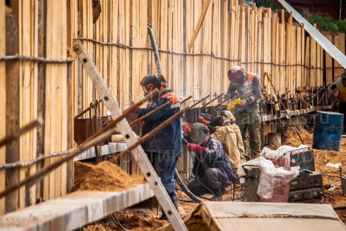
- you can not use the impact method of immersing the sheet piles;
- construction works in the pit associated with the use of heavy equipment should be reduced to the maximum.
In cases where construction work is carried out close to the neighboring house and the soles of the foundations are at the same level, construction is carried out by grappling. Each subsequent capture is done at the end of the foundation installation on the previous segment.
When developing deep pits, when the base of the foundation of a new house is located lower than the old one, it is necessary to install a sheet pile fence or a wall in the ground. You should also carefully carry out dewatering, as it can provoke additional soil subsidence.
Another development risk may arise in the presence of underground utilities. For the period of excavation, they should be lifted and suspended in a recess. The pipelines are placed in protective steel casings. If communications were discovered directly in the process of work, excavation continues manually. It is imperative to notify the organization that is responsible for these communications.
We will carry out excavation and removal of soil quickly, efficiently and absolutely safely for the existing development.
Development of a pit in Moscow? Contact us!
We carry out preliminary cycle works throughout Russia, provide services for any construction:
- pits for foundations and underground structures;
- trenches for communications;
- development of foundation pits for power transmission line supports;
- installation and strengthening of sheet piling for any purpose - for construction pits, hydraulic facilities, road works, collectors, etc.;
- preliminary studies;
- pile testing;
- design;
- dewatering;
- leader drilling;
- organization of the construction site.
- affordable price for excavation and other services;
- qualified specialists;
- all the necessary equipment is available;
- a wide range of sheet piles;
- sRO certificate;
- fast terms;
- quality assurance.
Leave a request for a consultation with a technical specialist
Find out how much you can save with us


