Driven piles are arranged directly on the construction site, at the site of a future building or structure.
Depending on the method of constructing wells and placing concrete in them, there are two types of rammed piles:
and) piles for which wells are drilled; there can be two ways to place concrete:
b) piles for which holes in the ground are formed by immersion steel pipe with a closed end, and the concrete is compacted by frequent ramming using hammer blows on the pipe (often rammed piles) or using vibration from a vibrator.
The walls can be fastened:
1.with casing (dry method)extracted from the well as the concrete is poured, and
Dry method applicable in stable soils; its technology is as follows (Fig. VI.10). Rotary drilling in the ground drills a well of the required diameter and to a given depth. After the bottom hole of the well reaches the design mark, if necessary, the lower part of the well is broadened with special wideners. After acceptance of the well according to the act, a reinforcing cage is mounted in it and concreted using the method of a vertically moving pipe (VTP). As the concrete is poured, the concrete-cast pipe is removed from the well. The concrete mix is \u200b\u200bcompacted using vibrators mounted on the receiving hopper of the concrete pipe.
2.without casing (wet method)when concrete is laid using a clay mortar (called bentonite);
Without casing you can also arrange bored piles (Fig. VI. 11). Here, as a formwork that prevents the collapse of the walls of the well, clay solution is used, which enters the well through a hollow drill rod. Due to the hydrostatic pressure exerted by this solution, the density of which is 1.2 ... 1.3 g / cm 3, piles are arranged without casing. Clay solution is prepared at the work site mainly from bentonite clays, and while drilling it is injected into the well. Rising up the borehole along its walls, the clay slurry enters the sump, from where it is returned by the pump to the drill rod for further circulation. Then a reinforcing cage is installed in the well. The concrete mix is \u200b\u200bfed using a vibrating bunker with a concrete-cast pipe, which is lowered into the well. The vibrated concrete mixture, entering the well, displaces the clay solution. As the well is filled with concrete mixture, the concrete pump is removed.

The considered method of borehole wall fixing is the simplest. However, it is not reliable enough and is very laborious when performing work in winter.
Installation of bored piles with casing of borehole walls (Fig. VI. 12) is possible in any geological and hydrogeological conditions. Casing pipes can be left in the ground or removed from boreholes during the piling process (inventory pipes). Casing sections are usually connected with specially designed joints or by welding. Casing pipes are immersed in the process of drilling a well with hydraulic jacks, as well as by driving the pipe into the ground or vibrating. Wells are drilled in a rotary or percussion way with special installations.
When shock When drilling, the casing sinks into the ground as the well is developed. In this case, individual sections of casing pipes are increased as needed.
When rotational In the drilling method, the leader is first drilled to the length of the casing section, after which the casing is immersed in the well. Then the next section of the well is drilled, after which the next section of the casing is built up and immersed in the well. These operations are repeated until the completion of drilling the well to the design mark.
After stripping the bottom hole and installing the reinforcement cage in the well, the well is concreted using the HMW method. As the well is filled with concrete, the inventory casing is removed. At the same time, a special system of jacks mounted on the installation imparts a reciprocating and rotary motion to the casing pipe, additionally compacting the concrete mixture. At the end of the concreting, the pile head is molded in a special inventory conductor.

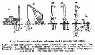
Driven piles are often made with a broadened bottom - the fifth. The broadening is done with special drills, as well as by detonating an explosive (camouflage piles). The broadening is done to increase the bearing capacity of the pile.
Camouflage piles are made as follows (Fig. VI. 13). First, a well is drilled, a casing is lowered into it. An explosive is placed at the bottom of the well, which is covered from above with a layer of 0.7 ... 1 m of cast concrete. " The resulting concrete plug is needed so that the energy of the explosion is directed to the formation of a cavity in the soil. The cavity is then filled with concrete and the pile is concreted in the usual way.
Frequency rammed piles are arranged by driving casing pipes resting on a metal tip. Then, in the cavity formed by the casing, a reinforced (or unreinforced) pile is arranged.
Frequency rammed piles (Fig. VI. 14) are arranged using a special pile driver. A hammer and a casing, which has a head in the upper part, are lifted onto the pile driver with a winch. A metal shoe with a resin rope is placed on the lower end of the casing to prevent water from entering the pipe. Under the influence of hammer blows, the casing is immersed to the design mark. When submerging, the pipe pushes the soil particles apart and compacts it. Then the hammer is raised and the reinforcement cage is lowered into the pipe cavity (if the piles are reinforced). From the vibrating bucket through a funnel, a concrete mixture with a cone draft of 8 ... 10 cm is fed into the cavity of the casing pipe.
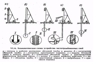
In parallel with the laying of the mixture, the casing is removed (pulled) by a small amount and again upset with a hammer blow to compact the concrete, with the metal shoe remaining at the base of the pile.
AT last years began to arrange soil-concrete piles, for which they use drilling and crane machines with a hollow drill rod, which has a mixing drill at the end with cutting and mixing blades. A water-cement slurry made in a mortar mixer is injected through the rods with a mortar pump. The mixing drill, during reverse rotation and extraction, compresses the soil saturated with a water-cement emulsion layer by layer. The result is a ground-concrete pile fabricated on site without excavation. In fig. U1.15 shows a schematic diagram of the device of soil-driven piles.

TYPICAL TECHNOLOGICAL CARD (TTK)
DEVICE OF FOUNDATIONS FROM DRILLED PIECES IN THE CONDITIONS OF EXISTING BUILDING AND RECONSTRUCTION
1 AREA OF USE
1 AREA OF USE
A typical technological map was developed for the construction of foundations from bored piles in the conditions of existing building and reconstruction.
It is intended for use by construction and installation organizations in the development of design estimates and work production projects.
When constructing buildings on pile foundations in the cramped conditions of urban development, dynamic loads acting on nearby buildings are a serious problem. The solution to this problem is possible with the use of bored pile technology.
The area of \u200b\u200bapplication of bored piles in all soils, except for rocky and coarse-grained, incl. flooded, structurally unstable without the use of inventory casing pipes or thixotropic solutions in cramped urban conditions with an approach to existing buildings up to 1 m.At the same time, when carrying out engineering and geological surveys, special attention should be paid to the examination of the places of foundation construction in order to identify various kind of obstacles (rocky layers, boulders larger than 25 cm, etc.).
Work can be carried out on the installation of bored piles with a diameter of 400-1200 mm and a depth of up to 25 m in various soil conditions for construction pile foundations near existing buildings with the use of imported equipment from "Casagranda S-40" (Italy).
Driven pile technology
Rammed piles are arranged in place of their future position by filling the well (cavity) with concrete or sand. Currently, a large number of solutions are used for such piles. Their main advantages:
the ability to manufacture any length;
absence of significant dynamic impacts during piling;
applicability in cramped conditions;
applicability when strengthening existing foundations.
Driven piles are made of concrete, reinforced concrete and soil, and it is possible to install piles with a widened heel. The method of piling is simple - a concrete mixture or soils, mainly sandy, are fed into pre-drilled wells for filling.
The following types of rammed piles are used - A.E. Strauss' piles, bored, pneumatic, vibro-rammed, frequency-rammed vibration-rammed, sand and soil concrete. The length of the piles reaches 20 ... 30 m with a diameter of 50 ... 150 cm. The piles manufactured using the installations of the companies Kato, Benoto, Liebcher can have a diameter of up to 3.5 m, a depth of up to 60 m, and a bearing capacity of up to 500 tons.
Features of the technology of piling works in conditions of reconstruction
The specifics of the production of pile works. During the reconstruction and technical re-equipment of enterprises, it is often necessary to strengthen the foundations or increase their bearing capacity. Under these conditions, various methods of supplying additional piles are used, the "wall in the ground" method, and a modified sinkhole method.
Installation of additional piles. With this method, bored and pressed multi-section piles are usually used, immersed in the corners of the foundation and receiving the load through a reinforced concrete frame arranged along its perimeter - a grillage. However, a more efficient solution is to install piles of hardened soil or rammed piles directly below the base of the existing foundation using "jet technology". This piling technology includes the following main processes:
drilling before subgrade wells with a diameter of 100 ... 150 mm through the lower step of the foundation at its corners, and, if necessary, between the corners;
lowering through the drilled hole in the foundation of the jet monitor and subsequent driving of a small-diameter well in the ground to the design depth by breaking the soil with a high-pressure jet from the monitor;
expansion of the well to the design cross-section by gradually raising the monitor, through the nozzle of which a water jet or a soil-strengthening solution enters, as a result of which a pile of hardened soil is formed.
It is possible to install a reinforcing cage in the well that goes into the existing foundation, followed by filling the well with a concrete mixture if the bearing capacity of the soil piles is insufficient.
When bringing soil piles under the foundations using the jet technology, three of its options are possible: one-, two- and three-component, differing in the number of components, the composition of the equipment and the bearing capacity of the resulting soil piles.
One-component technology provides for soil erosion by one or two oppositely directed streams of strengthening solution. The solution can be prepared in advance (cement-sand or cement-clay), or the required composition can be obtained by separate feeding of its components to the nozzles. Mixing will take place directly at the exit from the nozzle (liquid glass and hardener, cement-sand mortar and chemical additives-hardening accelerators, etc.). With one-component jet technology, the soil is eroded within a radius of 200 ... 350 mm from the nozzle, the diameter of the column of the soil pile is 0.5 ... 0.7 m.
Two-component inkjet technology carried out by the simultaneous supply of a stream of strengthening solution and a circular air stream concentric to it. The erosion of the soil with a mortar-air jet occurs within a radius of 1.0 ... 1.5 m, and the diameter of the soil pile reaches 2 ... 3 m. three-component technology additionally, additives are added to the soil, accelerating the process of pile formation.
With the jet technology, it is possible to obtain piles of various sections: screw, tapered, with transverse diaphragm discs, etc. Due to the developed lateral surface load bearing capacity piles are 1.5 ... 1.8 times higher than those of circular cross-section piles.
Screw piles are arranged by lifting a monitor having one or more side nozzles located one above the other with a simultaneous rotation around its vertical axis. The number of propeller blades on such piles corresponds to the number of nozzles on the monitor. The pitch of the propeller blades is determined by the lifting speed of the monitor.
Indentation of multi-section piles. Multi-section piles usually consist of three or more prefabricated short sections. These sections are sequentially joined as they are pressed into the ground by jacks or other mechanisms to a position at which the design bearing capacity is provided. The jack is installed under the sole of the existing foundation, under a special beam or inventory thrust device, anchored for fixed structures and adjacent buildings. For the installation of multisection piles, steel pipes with a diameter of 245 ... 400 mm with a shoe or a welded bottom end are used. Pile sections with a length of about 1 m are joined by welding as they are pressed in. After pressing, the pile cavity is filled with a concrete mixture. Reinforced concrete sections of piles with a section of 30x30 and a length of 60, 90 and 120 cm with a pin joint of the sections are used.
The advantages of multisection piles are that indentation is carried out in the static pile test mode, there are no dynamic effects during pile driving, high reliability of reinforcement of structures and constant monitoring of the pile bearing capacity during driving is ensured.
Modified sinkhole method... This method makes it possible to increase the bearing capacity of the soil mass under the existing foundation by enclosing the soil in a reinforced concrete shell, where the soil can perceive high pressures, since it is located in the closed volume of the sinkhole and is subjected to a triaxial stress state. The modified sinkhole method differs from the traditional one in that the soil is excavated from the outside, not inside the sinkhole. After excavation to the level of the lower step of the foundation, a well shell (prefabricated or monolithic) is arranged, it is lowered with soil development along the outer contour, and then the walls of the shell are increased. Work is carried out sequentially until the shell is immersed at the design level.
Bored piles.
A characteristic feature of the device of bored piles is preliminary drilling of wells to depth assignments.
The very first in our country, on the basis of which the existing varieties of bored piles are used, are A.E. Strauss' piles, which were proposed in 1899. Manufacturing of piles includes the following operations:
drilling a well;
lowering the casing into the well;
extraction of crumbling soil from the well;
filling the well with concrete in separate portions;
compacting concrete in these portions;
gradual extraction of the casing.
A pipe with a diameter of 25 ... 40 cm is carefully lowered into a well drilled to the design mark (5 ... 12 m) and then loaded with a concrete mixture. After filling the well to a depth of about 1 m, the concrete mixture is rammed and the casing pipe is slowly raised up until the thief, until the height of the mixture in the pipe decreases to 0.3 ... 0.4 m. The concrete mixture is loaded again and the process is repeated. Considering that the borehole diameter is larger than the casing pipe diameter and the surface of the drilled soil turns out to be uneven, rough, when filling the casing pipe with concrete mixture, lifting it and compacting the mixture, the concrete will fill the entire free volume, including the gap between the borehole walls and the casing pipe. Part of the concrete and laitance will penetrate into the soil, increasing its strength.
The disadvantages of this method are the impossibility to control the density and solidity of concrete over the entire height of the pile, the possibility of washing out the unsecured concrete mixture by groundwater.
Reinforcement of piles is carried out only in the upper part, where metal rods are installed to a depth of 1.5 ... 2.0 m in fresh concrete for their subsequent connection with the grillage.
Depending on the soil conditions, bored piles are arranged in one of the following ways - dry (without fixing the walls of the wells), using a clay solution (to prevent the collapse of the walls of the well) and with the casing of the well.
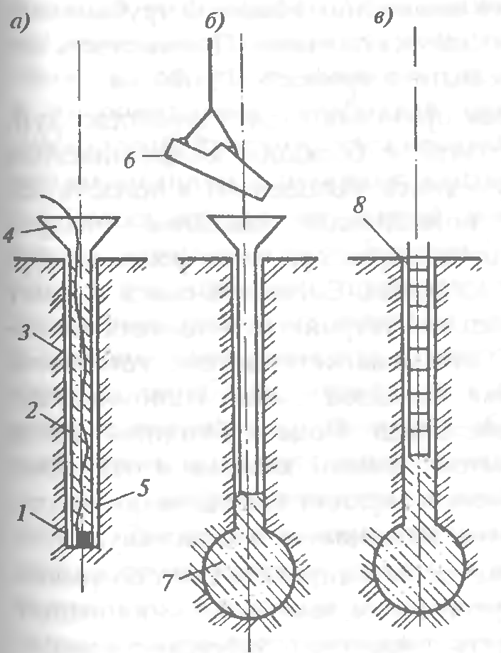
Dry method applicable in stable soils (subsidence and clayey solid semi-solid and tough-plastic consistency), which can hold the walls of the well (Fig. 1). A well of the required diameter is drilled out by rotary drilling in the ground to a given depth. After accepting the well in the prescribed manner, if necessary, a reinforcing cage is mounted in it and concreted using the method of a vertically moving pipe.
Fig. 1. Technological scheme of the device of bored piles by dry method:
and - well drilling; b - drilling out the widened cavity; at r - installation of a concrete pipe with a vibrating bunker; d - well concreting using the vertically movable pipe (VTP) method; e - lifting of the concrete pipe; 1 - drilling rig; 2 - drive; 3 - auger working body, 4 - well; 5 - dilator, 6 - widened cavity; 7 - reinforcing cage; 8 - jib crane; 9 - conductor-branch pipe; 10 - vibrating hopper; 11 - concrete pipe; 12 - bucket with concrete mix; 13 - widened pile heel
Concrete pipes used in construction, as a rule, consist of separate sections and have joints that allow you to quickly and reliably connect the pipes. Sections of concrete pipes with a length of 2.4 ... 6 m at the joints are fastened with bolts or locks, at the first section a receiving hopper is attached through which the concrete mixture is fed into the pipe. A concrete-cast pipe is lowered into the well to the very bottom, the concrete mixture is fed into the receiving funnel from a concrete mixer or with the help of a special loading hopper, vibrators are fixed on the same funnel, which compact the laid concrete mixture. As the mixture is laid, the concrete-cast pipe is removed from the well. At the end of the concreting of the well, the pile head is molded in a special inventory conductor, and in winter it is additionally reliably protected. Using the considered technology, bored piles with a diameter of 400 to 1200 mm are produced using the dry method, the length of the piles reaches 30 m.
Application of mud... The installation of bored piles in weak water-saturated soils requires increased labor costs, which is due to the need to fix the borehole walls to protect them from collapse (Fig. 2). In such unstable soils, a saturated clay solution is used to prevent the collapse of the borehole walls. bentonite clays with a density of 1.15 ... 1.3 g / cm, which exerts hydrostatic pressure on the walls, temporarily holds together individual soils, especially watered and unstable, while keeping well walls from collapsing well. This is also facilitated by the formation of a mud cake on the borehole walls due to the penetration of the solution into the soil.
Fig. 2. Technological diagram of the installation of bored piles under clay mortar:
and - well drilling; b - device for an expanded cavity; at - installation of a reinforcing cage; r - installation of a vibrating bunker with a concrete cast pipe; d - concreting of the well using the VCT method; 1 - well, 2 - drilling rig; 3 - pump; 4 - clay mixer; 5 - pit for mud; 6 - expander; 7 - barbell; 8 - jib crane; 9 - reinforcing cage; 10 - concrete pipe; 11 - vibrating hopper
Wells are drilled in a rotary way. The clay solution is prepared at the work site and, while drilling, is fed into the well through a hollow drill rod under pressure. As the drilling progresses, the solution under hydrostatic pressure from the drilling site, meeting the resistance of the soil, begins to rise up along the walls of the well, carrying out the soils destroyed by the drills, and reaching the surface, it enters the sump sump, from where it is pumped back into the well for further circulation.
The mud, which is under pressure in the well, cements the soil of the walls, thereby preventing the penetration of water, which makes it possible to exclude the use of casing pipes. After the completion of the well drilling, a reinforcing cage is installed into it, if necessary, the concrete mixture from the vibrating bunker through the concrete pipe falls to the bottom of the well, rising upwards, the concrete mixture displaces the clay solution. As the well is filled with concrete, the concrete pipeline is lifted.
Currently, a special polymer concentrate based on polyacrylamide is being successfully tested, which, during hydration, forms a colloidal drilling fluid that creates a protective film on the wellbore walls, which, in combination with excessive hydrostatic pressure, prevents them from shedding. Drilling in difficult geological conditions without the use of casing pipes showed the integrity of the bored pile throughout the entire depth after pumping concrete into it and the absence of any sagging or depressions of concrete on the lateral surface of the pile. The use of a colloidal solution can significantly increase the productivity of drilling operations, reduce their cost and labor intensity, and sharply reduce the need for casing without compromising the quality of work.
Well casing... Piling by this method is possible in any hydrogeological conditions; casing can be left in the well or removed from the well during the pile fabrication process (Figure 3). Casing pipes are connected to each other using locks of a special design (if these are inventory pipes) or by welding. Wells are drilled in a rotary or percussion way. The immersion of the casing pipes in the ground during the drilling of the well is carried out with hydraulic jacks.
Fig. 3. Technological diagram of the device of bored piles using casing pipes:
and - installation of a conductor and well drilling; b - immersion of the casing; at - well drilling; r - building up the next link of the casing; d - bottom hole cleaning; e - installation of a reinforcing cage; f - filling the well with concrete mix and removing the casing; 1 - a working body for drilling a well; 2 - well; 3 - conductor; 4 - drilling rig; 5 - casing pipe; 6 - reinforcing cage; 7 - concrete pipe; 8 - vibrating hopper
After stripping the bottom and installing the reinforcement cage, the well is concreted using the method of a vertically movable pipe. As the well is filled with concrete, they can also extract the inventory casing. A special system of jacks, mounted on the unit, imparts a reciprocating movement to the pipe, due to which the concrete mixture is additionally compacted. Upon completion of the concreting of the well, the pile head is formed. An installation for the manufacture of rammed piles using casing pipes with the extraction of soil from the pipe with a vibrating grab is found (Fig. 4).
Fig. 4. Technological scheme for manufacturing rammed piles with excavation under the protection of casing pipes:
and - immersion of the casing with a vibrating unit; b - extraction of soil from the casing with a vibrating grab; at - pile concreting; r - extraction of the casing with a vibrating unit; 1 - casing pipe; 2 - vibration unit; 3 - vibrating grab; 4 - reinforcing cage; 5 - a bucket with concrete mix
Bored piles with widened heel... The diameter of such piles is 0.6 ... 2.0 m, the length is 14 ... 50 m. There are three ways of arranging pile widening. The first way is bursting reinforced ramming concrete mixture in the lower part of the well, when it is impossible to assess the quality of the work, the shape (what the heel of the broadening has become), how much the concrete has mixed with the soil and what is its bearing capacity.
In the second method, the well is drilled with a machine having a special device in the form of an opening knife on the drill string. To form a widening of the well with a diameter of up to 3 m (Fig. 5), the knife is opened by a hydraulic mechanism controlled from the surface of the earth. When the rod rotates, the knives cut the soil, which falls into the bucket located above the expander. After several operations of cutting the soil with knives and extracting it to the surface, an expanded cavity is formed in the soil. A mud from bentonite clays is fed into the well, which circulates continuously and ensures the stability of the well walls. When the broadening device is used, the cavity is drilled out simultaneously with the supply of fresh mud to the well until the complete replacement of the mud contaminated with soil. After completing the drilling of the well to the design depth, the drill string with the reamer is removed, and the reinforcement cage is installed in the well. Concreting is carried out by the method of a vertically moving pipe, when at the same time a concrete mixture is fed into the pipe and lifted. The concrete mixture, in contact with a viscous clay mortar, does not reduce its strength, the cement binder is not washed out of the mixture. The concrete mix squeezes the slurry up the pipe and through the gap between the pipe and the well. The lower end of the concrete-cast pipe must be permanently buried in the concrete mixture to a depth of about 2 m; concreting is carried out continuously so that there are no layers of clay solution in the concrete.
Fig. 5. Drilling out a cavity in the ground with a reamer:
and - the position of the reamer during drilling the well; b - the same, in the process of drilling out the cavity; 1 - soil collector; 2 - cutting knives; 3 - well; 4 - barbell; 5 - widened cavity
Explosive way broadening devices (Fig. 6). A casing is installed in the drilled well. An explosive charge of the calculated mass is lowered to the bottom of the borehole and the wires from the detonator are brought out to the explosive machine located on the surface. The well is filled with concrete mixture 1.5 ... 2.0 m, the casing is raised by 0.5 m and an explosion is made. The energy of the explosion compacts the soil and creates a spherical cavity, which is filled with concrete from the casing. After that, portions and with the necessary compaction fill the casing pipe with concrete mixture to the top.
Fig. 6. Technological scheme of piles with camouflage broadening:
and - lowering the explosive charge and filling the well with a concrete mixture; b - the rise of the concrete pipe and the formation of a broadened heel by the explosion; at - ready-made rammed pile with camouflage broadening; 1 - explosive charge; 2 - wire to the blasting machine; 3 - casing pipe; 4 - receiving funnel; 5 - concrete mix; 6 - bucket with concrete mix; 7 - widened heel; 8 - reinforcing cage
Bored pile with shoe... The peculiarity of the method is that a casing is lowered into the drilled well, which has a loosely supported cast-iron shoe at the end, which is left in the ground after the casing is immersed to the required depth. By batchwise loading the concrete mixture, regularly compacting it and gradually removing the pipe from the well, a ready-made rammed concrete pile is obtained.
Concrete piles... The fundamental difference of the method is that the casing pipe up to 40 ... 50 m long has a rigidly fixed shoe in the lower part. After reaching the bottom of the well, the pipe remains there, is not retrieved, but filled with concrete.
Underwater concreting used to protect the concrete mixture from erosion at a high level of sedentary groundwater... The concrete mixture is fed into the casing not through a chute, but under pressure through a pipeline submerged to the very bottom of the well. Thanks to the pressure, the mixture is squeezed out of the pipe, fills the well space from below and begins to rise upward, pushing the water in the well upward. In the process of filling a well with a concrete mixture, it is necessary to ensure that the concrete-cast pipe rises at the same speed as the casing pipe, the bottom of the pipe is constantly 30 ... 40 cm below the top of the laid concrete mixture.After the well is completely filled, the top layer of concrete mixture with a thickness of 10 ... 20 cm in contact with water is cut off.
In flooded soils, pressure concreting of rammed piles can be used, which consists in continuous injection of concrete mixture to the entire height of the well under the influence of hydrostatic pressure generated by concrete pumps. Pressure concreting excludes mixing of the concrete mixture with water, clay solution or slag (drilling materials). The injection rate is set on the basis of the conditions for the continuity of the process of concreting the pile and unimpeded extraction of the casing after filling the well with concrete before setting. The mobility of the injected concrete mixtures should be within 18 ... 24 cm.
Compressed-air piles... Piles are used when constructing foundations in water-saturated soils with a high filtration coefficient. In this case, the concrete mixture is placed in the cavity of the casing pipe at a constant high blood pressure air (0.25 ... 0.3 MPa), which is supplied from the compressor through the receiver, which serves to smooth out pressure fluctuations. The concrete mixture is fed in small portions through a special device - a sluice chamber, which operates on the principle of pneumatic injection units used to transport concrete mixture. The airlock is closed with special valves. The concrete mixture is fed into the chamber with the lower valve closed and the upper open; when the chamber is filled with a mixture, the upper valve closes, the lower, on the contrary, opens, the mixture is squeezed into the well.
Driven piles of any type should be concreted without interruption. When the piles are located less than 1.5 m from one another, they are carried out through one, so as not to damage the newly concreted ones.
The missed wells are concreted during the second sinking of the concrete-casting installation, after being set with previously concreted piles of sufficient strength and bearing capacity. This sequence of works provides for the protection of both finished wells and freshly concreted piles from damage.
Bored piles have a number of disadvantages that hinder their wider application. Such disadvantages include a small specific bearing capacity, high labor intensity of drilling operations, the need to anchor wells in unstable soils, the complexity of concreting piles in water-saturated soils and the difficulty of quality control of the work performed.
Piling in pushed holes is quite effective in dry soils. When installing such piles, a compacted zone is created in the soil, the strength of the soil increases and its deformability decreases. The installation of rammed piles in compacted wells is performed by pushing methods without extracting soil to the surface.
This work technology is based on the formation of a well by multiple dropping from the height of the cast-iron cone, as a result of which the well is punched. Then the well is filled in portions with concrete, crushed stone or sand and compacted until a broadened part is formed at the base of the pile. In the upper part, when laying the concrete mixture, it is compacted by vibration. Many modifications of this method have been developed. The formation of wells and cavities in the soil without its excavation is carried out: punching with cores and casing pipes using hammers, punching with vibratory pilers and vibrating hammers, punching with shells and ramming, punching with pneumatic punches, expanding with hydraulic seals, punching with screw devices.
Found application stamping method using a percussion rope drilling machine (Fig. 7). First, a leader well is drilled to a depth of up to 1/2 of the length of the future pile, then the well is pierced with an impact tool to the required depth. A rigid concrete mixture is loaded into the lower part of the well with a column of 1.5 ... 2 m and a widened heel is arranged at the base of the pile with tamper blows. A casing is installed at the wellhead, a reinforcing cage is mounted and the upper part of the pile is concreted.
Fig. 7. Technological diagram of the device of bored piles with a stamped heel:
and - well drilling; b - installation of a casing in the well; at - backfilling of hard concrete mix into the well; r - ramming the concrete mixture into the base; d - extraction of the casing and installation of the reinforcement cage; e - concreting the pile shaft with compaction with a deep vibrator; f - pile head formwork; 1 - drilling machine; 2 - working mechanism with attachments for the device of a widened heel; 3 - casing, 4 - tray for loading rigid concrete mixture; 5 - rammer; 6 - jib crane; 7 - reinforcing cage; 8 - bucket with concrete mix; 9 - funnel; 10 - stamped broadened heel; 11 - top formwork
The method of vibrating piles is characterized by the presence of a vibrating former. Its hollow tip has blades at the bottom and is connected via a rigid bar to a vibrator. Under the action of the latter, the tip is immersed in the ground and forms a well, which, as the tip is immersed, is filled with a concrete mixture from a hopper installed above the wellhead. After drilling the well, the tip is slightly raised, while its blades open, through the cavity of the tip, the concrete mixture falls to the bottom of the well. A lost cast iron shoe can be used instead of self-opening sashes.
Rammed piles are used in dry, bonded soils. A steel casing pipe with a removable reinforced concrete shoe at the end is immersed into the drilled well with the help of a vibratory driver fixed to the excavator. The pipe cavity is filled to 0.8 ... 1.0 m with a concrete mixture, it is compacted using a special ramming rod suspended from a vibrator (Fig. 8). As a result, the shoe, together with the concrete mixture, is pressed into the ground, and a widened heel is formed. The casing pipe is filled with concrete mixture in portions with constant compaction. As the well is filled with concrete, the casing is lifted by an excavator while the vibratory pile driver is operating, which significantly reduces the adhesion of the pipe to the concrete during its extraction.
Fig. 8. Technological diagram of the device of rammed piles:
and - well formation; b - laying the first batch of concrete; at - compacting the concrete mix with a tamper bar rigidly connected to the vibratory pile driver; r - laying and compaction of subsequent layers of concrete mix; d - extraction of the casing and installation of the reinforcement cage in the head of the pile
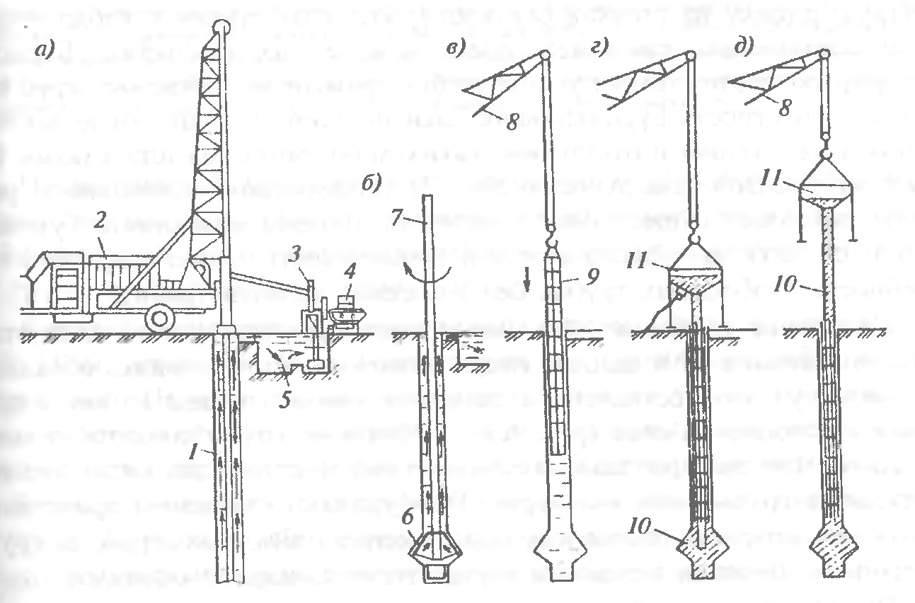
Frequency rammed piles arrange by driving the casing into the drilled well together with a cast iron shoe put on at the end, which remains in the ground (Fig. 9). Loading the concrete mixture into the casing is carried out in portions in 2 ... 3 steps. The cross-section of the pile is formed and the casing is pulled out of the well using a double-acting hammer that transfers the force through the casing.
Fig. 9. Technological diagram of the device of rammed piles:
and b - installation of a reinforcing cage; at - supply of concrete mixture into the pipe cavity; r - extraction of the casing with simultaneous consolidation of the concrete mixture; 1 - casing pipe; 2 - pile driver; 3 - double action hammer; 4 - reinforcing cage; 5 - bucket with concrete mix; 6 - receiving funnel; 7 - cast iron shoe
A casing pipe with a cast iron shoe is immersed in the ground to the design mark under the influence of hammer blows. When submerging, the pipe pushes the soil particles apart and compacts it. When the pipe reaches its lowest point, a reinforcing cage is lowered into its cavity (if necessary), then a rigid concrete mixture with a cone draft of 8 ... 10 cm is fed through a funnel from a vibrating bucket to the cavity of the casing pipe.
After filling the casing to a height of 1 m, they begin to raise it, while the shoe slides off under the action of the concrete mixture pressing on it, which begins to fill the well. A double-acting hammer connected to the casing produces frequent paired blows directed alternately up and down. From blows directed upwards in 1 min, the pipe is removed from the ground by 4 ... 5 cm, and from blows directed downwards, the pipe is upset by 2 ... 3 cm. The ramming of the concrete mixture entering the well under the action of its own mass is carried out due to the impacts of the lower edge of the casing pipe and the friction of concrete against the pipe walls as a result of the vibration of the hammer, in connection with which, the entire concrete mixture is constantly in the process of vibration and, as a result, is well compacted. As a result, the soil in the lower part of the well is compacted, part of the concrete mixture is pressed into the walls of the well, increasing their strength.
This compaction of concrete in the casing is continued until the pipe is completely removed from the ground. If necessary, external vibrators are attached to the extracted casing pipe, which make it possible to better compact the upper layers of the concrete mixture. Frequency rammed piles can be made reinforced. Reinforcement is carried out by calculation, but in most cases, the reinforcement cage is used only in the upper part of the pile to connect to the reinforcement monolithic grillage... If the reinforcement is provided for the entire height of the pile, then the reinforcement cage is lowered into the casing before concreting begins.
Sand rammed piles - the cheapest way to compact soft soils. A steel casing with a shoe is immersed in the ground using a vibratory pile driver (Fig. 10). Having reached the design mark, it is partially filled with sand, when the casing is raised due to the mass of sand, it is separated from the shoe, and with the help of a vibratory pile driver it is extracted to the surface, while the soil is compacted from vibration shakes. Additional and effective sealing can be achieved by spilling the well with water. Use pipes with a diameter of 32 ... 50 cm; during extraction, a layer of sand with a height of 1.0 ... 1.25 m must always be in the pipe.The method is applicable for wells up to 7 m deep.
Fig. 10. Layout of the device of sand (soil) rammed piles:
and - immersion of the casing; b - pipe extraction; at - drop-down tip; 1 - vibrator; 2 - casing pipe; 3 - hinge; 4 - tip flap; 5 -ring
Ground concrete piles. Soil-concrete piles have been used, which are arranged using drilling rigs with a hollow drill rod having a mixing drill at the end with special blades cutting and simultaneously mixing the mixture. After drilling a well in soft sandy soils to the desired mark, a water-cement suspension (solution) is fed into the hollow rod under pressure from a mortar mixing plant. The drill rod slowly begins to rise upward with reverse rotation, the soil is saturated with cement mortar and is additionally compacted with a drill. The result is a sand-cement pile fabricated on site without excavation.
Screwed piles... Often, pits for buried structures have to be arranged near existing buildings. Driving piles and sheet piles can lead to their deformation due to the resulting dynamic effects. When installing bored piles, where the casing is immersed with advance sampling of soil from the pipe cavity, leakage is possible soil mass from under the adjacent foundations, which can also lead to deformations of existing buildings. The use of slurry wall methods or the use of mud to submerge the pipes increases the project cost.
Fig.11. Diagram of a screw-in pile:
1 - metal pipe; 2 - welding of the coil with the pipe; 3 - winding from reinforcement with a diameter of 10 ... 16 mm with a step of 200 ... 400 mm; 4 - cross-shaped blind or lost tip; 5 - crosspiece; 6 - metal disc
With these methods, the natural underground environment and its balance are disturbed, which can lead to undesirable results or to a serious increase in the cost of construction. In cases of dense building, it is advisable to use the screw-on pile method. The essence of the method is that the metal pipe is not driven into the ground, but screwed up (Fig. 11). A narrow auger made of reinforcement with a diameter of 10 ... 16 mm with a pitch of 200 ... 500 mm is wound onto the pipe at the factory. Depending on soil conditions, the pipe can be equipped with a plug with rippers, blind or loose, allowing, if necessary, to prevent water from entering the pipe body. When the pipe is screwed in, the surrounding soil is partially compacted, about 15 ... 25% of it is squeezed out.
If the pipe in the lower part is deaf, then after screwing to the design mark, a reinforcing cage is inserted into it and it is filled with concrete mixture. For pipes with a lost tip, a reinforcing cage is inserted into it, the pipe is filled with concrete, in the process of concrete setting, the pipe is unscrewed, a shoe remains in the ground, on which the reinforced concrete bored pile rests. With particularly dense soils, it is possible to pre-drill a well to a slightly shallower depth (up to 1 m) and the diameter of the well should be less than the diameter of the pipe. The diameter of the screwed pipes is 300 ... 500 mm, the length is from 4 to 20 m. It is important that the technology allows to carry out work near existing buildings at a height of 5 floors at a distance of about 40 cm, at a higher height - about 70 cm.
In recent years, foundations have become widespread in the form of powerful deep-laid supports with a high bearing capacity, built with the help of special machines (Fig. 12). The excavation is carried out using a grab bucket inside the sinking casing. During excavation, the lower end of the pipe should be below the bottom of the well. The face is cleaned with a grab bucket. After installing the reinforcement cage in the well, concreting is carried out using the method of vertically moving pipe; the deepening of the concrete pipe into the concrete mixture must be at least 1 m.
Fig. 12. Technological diagram of the device of bored piles with a diameter of 2 ... 3.5 m:
and - installation of a drilling rig; b - well drilling; at - face cleaning; r - installation of the reinforcing cage; d - installation of a concrete pipe; e - pile concreting; 1 - drilling rig; 2 - casing pipe; 3 - grab bucket; 4 - reinforcing cage; 5 - concrete pipe
2. FEATURES OF DESIGNING DRILL PILES AND PIPE FOUNDATIONS
2.1. The design and installation of bored piles is carried out in accordance with the requirements SNiP 2.02.03-85 "Pile foundations", SNiP 3.02.01-87 "Earthworks, foundations and foundations ", SNiP 2.03.01-84 "Concrete and reinforced concrete structures".
2.2. Loads and impacts, their combinations, reliability factors and operating conditions are determined in accordance with the requirements SNiP 2.01.07-85 Loads and Actions and Industry Design Codes.
2.3. Bored piles with the use of imported equipment are reinforced with welded spatial frames. Longitudinal working reinforcement must be evenly spaced around the circumference. The number of rods must be at least 6, and the diameter must be at least 18 mm. The distance between the longitudinal bars should be at least 40 cm. The longitudinal reinforcement bars should preferably be used from steel of class AIII.
Reinforcement cages should have fixing elements made of plastic tubes with a diameter of 90 mm and a length of 70 mm, providing the required thickness of the concrete cover, installed on transverse stiffening rings along the length of the pile.
2.4. The reinforcement frame, in addition to the basic requirements imposed by SNiPs, must have a rigidity sufficient to immerse it in a well filled with concrete. For this purpose, it must be manufactured welded with one-piece longitudinal rods bent into a cone at the bottom. If necessary, it is recommended to weld transverse stiffening rings with a height step of 2-3 m. It is preferable to have a minimum number of rods with a larger diameter.
2.5. Protective layer concrete should be at least 70 mm and ensured by installing clamps on transverse stiffening rings welded to the reinforcing cage.
; GOST 12730.5-84.
2.7. Changes in the design of foundations from bored piles, caused by the discrepancy between the actual geological, hydrogeological and other conditions adopted in the project, must be made by the design organization with prior agreement with the customer.
2.8. Work on the installation of bored piles should be preceded by the planning of the construction site at a given elevation with a breakdown of the axes of the structure and reliable fixing of the position of the rows of bored piles on the ground.
2.9. The layout of the axes of structures should be drawn up by an act, to which are attached layouts of the layout signs, data on the binding to the baseline and to the high-altitude support network. The correctness of the layout should be systematically checked during the production of work, as well as in each case of displacement of the points fixing the axes.
2.10. The deviations of the alignment axes of the rows of bored piles from the design ones should not exceed 1 cm per 100 m of the row; in the position of single bored piles - ± 0.05 of the pile diameter; with an ordinary or cluster arrangement of piles - ± 0.15 of the pile diameter.
Pile head deviations from design position vertically, it is allowed in the direction of overstating the heading mark up to 10 cm, and in the direction of underestimation - up to 20 cm.In all cases, the embedding of the pile head into the concrete of the grillage (excluding preparation) must be at least 10 cm.
The tangent of the angle of deviation of the vertical axis of the pile from the design position should not exceed 1/100 (deviations of the borehole wall from the plumb line should not exceed 10 cm for every 10 m of the borehole depth).
2.11. In winter, work on the installation of bored piles in flooded soils can be carried out at an outside air temperature of up to minus 10 ° C.
Work on the installation of bored piles at lower temperatures is possible with the adoption of special measures to ensure the normal operation of the drilling rig, equipped with an on-board system for monitoring the main parameters of the technological process, while carefully protecting the freshly laid concrete from freezing. These activities should be indicated in the work organization project.
2.12. The materials used for the preparation of concrete for bored piles must meet the requirements of GOSTs for binding materials.
2.13. For the manufacture of concrete mix used:
- cement for the preparation of concrete grade at least 300, resistant to the effects of an aggressive environment with a setting time of at least 2 hours. The use of aluminous, quick-setting and hot cements is not allowed;
- sand, crushed stone, gravel of fractions no more than 20 mm. The strength of gravel and crushed stone must be at least 800 kgf / cm;
- concentrates of lignosulfonates (LST) in accordance with the "Guidelines for the use of chemical additives in concrete". M., Stroyizdat, 1981.
Driven piles are arranged in place of their future position by filling the well (cavity) with concrete or sand. Currently, a large number of solutions are used for such piles. Their main advantages:
■ the ability to manufacture any length;
■ absence of significant dynamic impacts during piling;
■ applicability in confined spaces;
■ Applicability when reinforcing existing foundations. Driven piles are made of concrete, reinforced concrete and soil, and it is possible to install piles with a widened heel. The method of piling is simple - a concrete mixture or soils, mainly sandy, are fed into pre-drilled wells for filling.
It will add the following types of rammed piles - A.E. Ostrich, bored, pneumatic, vibration rammed, frequency rambo-she, vibration rammed, sand and soil concrete. The length of the piles reaches 20 ... 30 m with a diameter of 50-150 cm. The piles manufactured using the installations of the companies Kato, Benoto, Liebherr can have a diameter of up to 3.5 m, a depth of up to 60 m, and a bearing capacity of up to 500 tons.
Bored piles. A characteristic feature of the device of bored piles is preliminary drilling of wells to a given depth.
The very first in our country, on the basis of which all existing varieties of bored piles are used, are A.E. Ostrich, which were proposed in 1899. Making piles includes the following operations:
■ drilling a well;
■ lowering the casing into the well;
■ extraction of crumbling soil from the well;
■ filling the well with concrete in separate portions;
■ compacting concrete in these portions;
■ in the gradual extraction of the casing.
A pipe with a diameter of 25-40 cm is carefully lowered into a well drilled to the design mark (5-12 m) and then loaded with a concrete mixture. After filling the well to a depth of about 1 m, the concrete mixture is rammed and the casing pipe is slowly raised up until the height of the mixture in the pipe decreases to 0.3-0.4 m. The concrete mixture is loaded again and the process is repeated. Considering that the borehole diameter is larger than the casing pipe diameter and the surface of the drilled soil turns out to be uneven, rough, when filling the casing pipe with concrete mixture, lifting it and compacting the mixture, the concrete will fill the entire free volume, including the gap between the wellbore walls and the casing pipe. Part of the concrete and laitance will penetrate the soil, increasing its strength.
The disadvantages of this method are the inability to control the density and solidity of concrete over the entire height of the pile, the possibility of erosion of the non-set concrete mixture by groundwater.
Reinforcement of piles is carried out only in the upper part, where metal rods are installed to a depth of 1.5 ... 2.0 m in fresh concrete for their subsequent connection with the grillage.
Depending on the soil conditions, the bored piles are arranged * from one of the following methods - dry (without fixing the walls of the wells), using a clay solution (to prevent the collapse of the walls of the well) and with the casing of the well.
The dry method is applicable in stable soils (subsidence and clayey of solid semi-solid and tough-plastic consistency), which can hold the walls of the well (Fig. 6.13). A well of the required diameter is drilled out by rotary drilling in the ground to a given depth. After accepting the well in the prescribed manner, if necessary, a reinforcing cage is mounted in it and concreted using the method of a vertically moving pipe.
R and C. 6.13 Technological scheme of the device of bored piles by dry method:
a - well drilling; b - drilling out the broadened cavity; c - installation of a reinforcing cage, f - installation of a concrete-cast pipe with a vibrating hopper; e - concreting of the well by the method of vertically movable pipe (VPT), \u200b\u200be - lifting of the concrete pipe; Do a drilling rig; 2 -drive; 3 - screw working body, 4 - well, 5 - reamer; 6 - widened cavity; 7 - reinforcing cage; 8 - jib crane; 9 - conductor-branch pipe; 10 - vibrating hopper; II - concrete pipe; 12 - bucket with concrete mix; 13 - widened pile heel
Concrete pipes used in construction, as a rule, consist of separate sections and have joints that allow you to quickly and reliably connect the pipes. Sections of concrete pipes with a length of 2.4 ... 6 m at the joints are fastened with bolts or locks, at the first section a receiving hopper is attached through which the concrete mixture is fed into the pipe. A concrete-cast pipe is lowered into the well to the very bottom, the concrete mixture is fed into the receiving funnel from a concrete mixer or with the help of a special loading hopper, vibrators are fixed on the same funnel, which compact the laid concrete mixture. As the mixture is laid, the concrete-cast pipe is removed from the well. At the end of the concreting of the well, the pile head is molded in a special inventory conductor, and in winter it is additionally reliably protected. Using the considered technology, bored piles with a diameter of 400 to 1200 mm are produced using the dry method, the length of the piles reaches 30 m.
The use of mud. The installation of bored piles in weak water-saturated soils requires increased labor costs, which is due to the need to fix the borehole walls to protect them from collapse (Fig. 6.14). In such unstable soils, to prevent the collapse of the walls of wells, a saturated clay solution of bentonite clays with a density of 1.15-1.3 g / cm3 is used, which exerts hydrostatic pressure on the walls, temporarily bonds individual soils, especially watered and unstable ones, while holding the walls well wells from collapse. This is also facilitated by the formation of a mud cake on the borehole walls due to the penetration of the solution into the soil.
R and C. 6.14. Technological diagram of the device of bored piles under clay mortar:
a) - drilling a well; b - device for an expanded cavity; c - installation of the reinforcing cage; d - installation of a vibrating bunker with a concrete pipe; e - concreting of the well using the VCT method; At the well, 2 - drilling rig; 3 - pump; 4 - clay mixer; 5 - pit for mud b - expander, 7 - bar, 8 - jib crane, 9 - reinforcement cage; 10 - concrete pipe; II - vibrating hopper
Wells are drilled in a rotary way. The clay solution is prepared at the work site and, while drilling, is fed into the well through a hollow drill rod under pressure. As the drilling progresses, the solution under hydrostatic pressure from the drilling site, meeting the resistance of the soil, begins to rise up along the walls of the well, carrying out the soils destroyed by the drills, and coming to the surface, it enters the sump sump, from where it is pumped back into the well for further circulation.
The mud, which is under pressure in the well, cements the soil of the walls, thereby preventing the penetration of water, which makes it possible to exclude the use of casing pipes. After the completion of the well drilling, a reinforcing cage is installed into it, if necessary, the concrete mixture from the vibrating bunker through the concrete pipe falls to the bottom of the well, rising upward, the concrete mixture displaces the clay solution. As the well is filled with concrete, the concrete pipeline is lifted.
Currently, a special polymer concentrate based on polyacrylamide is being successfully tested, which, during hydration, forms a colloidal drilling fluid that creates a protective film on the wellbore walls, which, in combination with excessive hydrostatic pressure, prevents them from shedding. Drilling in difficult geological conditions without the use of casing pipes showed the integrity of the bored pile throughout the entire depth after the injection of concrete into it and the absence of any sagging or depressions of concrete on the lateral surface of the pile. The use of a colloidal solution can significantly increase the productivity of drilling operations, reduce their cost and labor intensity, and sharply reduce the need for casing without reducing the quality of work.
Casing of wells. Piling by this method is possible in any hydrogeological conditions; the casing can be left in or removed from the well during the pile fabrication process (Figure 6.15). Casing pipes are connected to each other using locks of a special design (if these are inventory pipes) or by welding. Wells are drilled in a rotary or percussion way. The immersion of the casing pipes in the ground during the drilling of the well is carried out with hydraulic jacks.

Figure 6.15. Technological diagram of the device of bored piles using casing pipes:
a - installation of a conductor and drilling of a well; b - immersion of the casing; c - penetration; d - building up the next link of the casing; d - bottomhole cleaning of the borehole y ^ scale of the armature of the yugoframe; »C - filling the well with a concrete mixture and extracting the casing-body for drilling the well; 2 - well; 3 - conductor; 4-drilling rig "5 - ssadnaya t ^ uba; b - reinforcing cage; 7 - concrete pipe; 8 - vibrating hopper
After stripping the bottom and installing the reinforcement cage, the well is concreted using the method of a vertically movable pipe. As the well is filled with concrete, they can also extract the inventory casing. A special system of jacks, mounted on the unit, imparts a reciprocating movement to the pipe, due to which the concrete mixture is additionally compacted. Upon completion of the concreting of the well, the pile head is formed. An installation is found for the manufacture of rammed piles using casing pipes with the extraction of soil from the pipe with a vibrating grab (Figure 6.16).
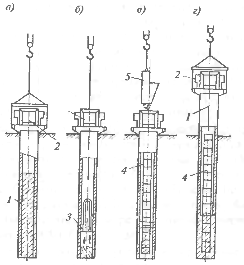
Figure: 6.16. Technological scheme for manufacturing rammed piles with excavation under the protection of casing pipes:
a - immersion of the casing with a vibrating unit; b - extraction of soil from the casing with a vibrating grab; c - pile concreting; d - extraction of the casing with a vibrating unit; / - casing; 2 - vibration unit; 3 - vibrating grab; 4 - reinforcing cage; 5 - a bucket with concrete mix
Bored piles with widened heel. The diameter of such piles is 0.6 ... 2.0 m, the length is 14 ... 50 m. There are three ways to construct pile extensions. The first method is the expansion of the soil by reinforced tamping of the concrete mixture in the lower part of the well, when it is impossible to assess the quality of work, the shape (what the heel of the broadening has become), how much concrete has mixed with the soil and what is its bearing capacity.
In the second method, the well is drilled with a machine that has a special device on the drill string in the form of an opening knife, to form a widening of the well with a diameter of up to 3 m (Fig. 6.17). The knife is opened by a hydraulic mechanism controlled from the ground. When the bar rotates, the knives cut the soil, which falls into the bucket located above the expander. After several operations of cutting the soil with knives and extracting it to the surface, a widened cavity is formed in the soil. A mud from benthokite mud is fed into the well, which circulates continuously and ensures the stability of the well walls. When the broadening device is used, the cavity is drilled out simultaneously with the supply of fresh mud to the well until the complete replacement of the mud contaminated with soil. After completing the drilling of the well to the design depth, the drill string with the reamer is removed, and the reinforcement cage is installed in the well. Concreting is carried out by the method of a vertically moving pipe, when at the same time a concrete mixture is fed into the pipe and lifted. The concrete mixture, in contact with a viscous clay mortar, does not reduce its strength, the cement binder is not washed out of the mixture. The concrete mix squeezes the slurry up the pipe and through the gap between the pipe and the well. The lower end of the concrete-cast pipe must be permanently buried in the concrete mixture to a depth of about 2 m; concreting is carried out continuously so that there are no layers of clay solution in the concrete.

Figure: 6.17. Drilling out a cavity in the ground with a reamer:
a - the position of the reamer during drilling the well; b - the same, in the process of drilling out the cavity; 1 - soil collection; 2 - cutting knives; 3 - well; 4 - barbell; 5 - widened cavity
The explosive method of the broadening device (Fig. 6.18). A casing is installed in the drilled well. An explosive charge of the calculated mass is lowered to the bottom of the borehole and the wires from the detonator are brought out to the explosive machine located on the surface. The well is filled with a concrete mixture 1.5 ... 2.0 m, the casing is raised by 0.5 m and an explosion is made. The energy of the explosion compacts the soil and creates a spherical cavity, which is filled with concrete from the casing. After that, pistons and with the necessary seal fill the casing pipe with concrete mixture to the top.
R and C. 6.18. Technological scheme of piles with camouflage broadening:
a - lowering the explosive charge and filling the well with a concrete mixture; b - the rise of the concrete-cast pipe and the formation of a broadened heel by the explosion; c - a finished rammed pile with camouflage broadening; 1 - explosive charge; 2 - wire to the blasting machine; 3 - casing pipe; 4 - buried funnel; J - concrete mix; b - a bucket with a concrete mixture; 7 - widened heel; 8 - reinforcing cage
Bored pile with shoe. [The peculiarity of the method is that a casing pipe is lowered into the drilled well, which has a loosely supported cast-iron shoe at the end, which is formed in the soil after immersion [of the casing pipe to the required depth. By batch-loading the concrete mixture, regularly compacting it and removing the pipe from the borehole, a finished rammed concrete pile is obtained.
Concrete piles... The fundamental difference of the method is that the casing pipe up to 40 ... 50 m long has a rigidly fixed shoe in the lower part. After reaching the bottom of the well, the pipe remains there, is not retrieved, but filled with concrete.
Underwater concreting used to protect the concrete mixture from erosion at a high level of low-mobile groundwater. The concrete mixture is fed into the casing not through a chute, but under pressure through a pipeline submerged to the very bottom of the well. Thanks to the pressure, the mixture is squeezed out of the pipe, fills the well space from below and begins to rise upward, pushing the water in the well upward. In the process of filling a well with concrete, it is necessary to ensure that the concrete-cast pipe rises at the same speed as the casing pipe, the bottom of the pipe is constantly 30 ... 40 cm below the top of the laid concrete mixture. After the well is completely filled, the top layer of concrete mixture with a thickness of 10 .. .20 cm in contact with water is cut off.
In flooded soils, pressure concreting of rammed piles can be used, which consists in continuous injection of concrete mixture to the entire height of the well under the influence of hydrostatic pressure generated by concrete pumps. Pressure concreting excludes mixing of the concrete mixture with water, clay solution or slag (drilling materials). The injection rate is set on the basis of the conditions for the continuity of the process of concreting the pile and unimpeded extraction of the casing after filling the well with concrete before setting. The mobility of the injected concrete mixtures should be within 18 ... 24 cm.
Compressed-air piles... Piles are used when constructing foundations in water-saturated soils with a high filtration coefficient. In this case, the concrete mixture is placed in the cavity of the casing at a constant high air pressure (0.25 ... 0.3 MPa), which is supplied from the compressor through the receiver, which serves to smooth out pressure fluctuations. The concrete mixture is fed in small portions through a special device - a sluice chamber, which operates on the principle of pneumatic injection units used to transport concrete mixture. The airlock is closed with special valves. The concrete mixture is fed into the chamber with the lower valve closed and the upper open; when the chamber is filled with a mixture, the upper valve closes, the lower, on the contrary, opens, the mixture is squeezed into the well.
The missed wells are concreted during the second sinking of the concrete casting installation, after being set with previously concreted piles of sufficient strength and bearing capacity. Such a sequence of works provides for the protection of both finished wells and fresh concrete piles from damage.
Bored piles have a number of disadvantages that hinder their wider application. Such disadvantages include a small specific bearing capacity, high labor intensity of drilling operations, the need to anchor wells in unstable soils, the complexity of concreting piles in water-saturated soils and the difficulty of quality control of the work performed.
Piling in pushed holes is quite effective in dry soils. When installing such piles, a compacted zone is created in the soil, the strength of the soil increases and its deformability decreases. The installation of rammed piles in compacted wells is performed by punching methods without extracting soil to the surface.
This work technology is based on the formation of a well by multiple dropping from the height of the cast-iron cone, as a result of which the well is punched. Then the well is filled in portions with concrete, crushed stone or sand and compacted until a broadened part is formed at the base of the pile. In the upper part, when laying the concrete mixture, it is compacted by vibration. Many modifications of this method have been developed. The formation of wells and cavities in the soil without its excavation is carried out: punching with cores and casing pipes using hammers, punching with vibratory pilers and vibrating hammers, punching with shells and ramming, punching with pneumatic punches, expanding with hydraulic seals, punching with screw devices.
Found an application of the punching method using a percussion-rope drilling machine (Fig. 6.19). First, a leader well is drilled to a depth of up to V2 of the length of the future pile, then the well is punched with a percussion tool to the required depth. A rigid concrete mixture is loaded into the lower part of the well with a column of 1.5 ... 2 m and the tamper tsars arrange a widened heel at the base of the pile. A casing is installed at the wellhead, a reinforcing cage is mounted and the upper part of the pile is concreted.
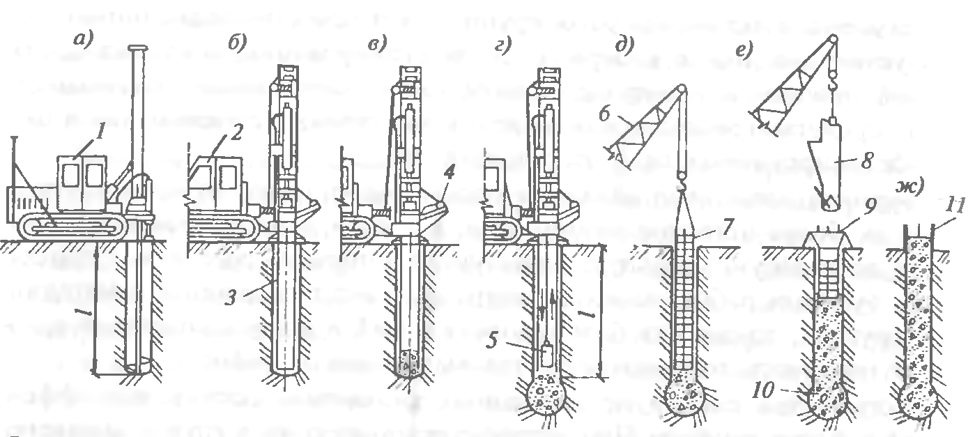
Figure: 6.19. Technological diagram of the device of bored piles with a stamped heel:
a - drilling a well: b - installing a casing in the well: c - backfilling a hard concrete mixture into the well, d ramming the concrete mixture into the base, O - removing the pipe with a casing and installing a reinforcing cage: c - concreting the pile shaft with compaction with a deep vibrator, w - pile head formwork, / - drilling machine; 2 - working mechanism with attachments for the device of a widened heel; 3 - casing pipe; 4 - tray for loading hard concrete mix; 5 - rammer; b - jib crane; 7 - reinforcing cage; 8 - buckets with concrete mix, 9 funnel, 10 - stamped broadened heel. 11 - top formwork
The method of vibrating piles is characterized by the presence of a vibrating shaper. Its hollow tip has blades at the bottom and is connected via a rigid bar to a vibrator. Under the action of the latter, the tip is immersed in the ground and forms a well, which, as the tip is immersed, is filled with a concrete mixture from a hopper installed above the wellhead. After drilling the well, the tip is slightly raised, while its blades open, through the cavity of the tip, the concrete mixture falls to the bottom of the well. A lost cast iron shoe can be used instead of self-opening sashes.
Rammed piles are used in dry, bonded soils. A steel casing pipe with a removable reinforced concrete shoe at the end is immersed into the drilled well with the help of a vibratory driver fixed to the excavator. The pipe cavity is filled to 0.8 ... 1.0 m with a concrete mixture, it is compacted using a special ramming rod suspended from a vibrator (Fig. 6.20). As a result, the shoe, together with the concrete mixture, is pressed into the ground, and a widened heel is formed. The casing pipe is filled with concrete mixture in portions with constant compaction. As the well is filled with concrete, the casing is lifted by an excavator while the vibratory pile driver is operating, which significantly reduces the adhesion of the pipe to the concrete during its extraction.
![]()
Fig- 6.20. Technological diagram of the device of rammed piles:
a - formation of a well, 6 - laying the first batch of concrete mixture; c - compaction of the concrete mixture with a tamper bar rigidly connected to the vibrator; d - laying and compaction of subsequent layers of concrete mix; e - extraction of the casing and installation of the reinforcement cage in the head of the pile
Frequency rammed piles are arranged by driving the casing into the drilled well together with a cast iron shoe put on at the end, which remains in the ground (Figure 6.21). Loading the concrete mixture into the casing is carried out in portions in 2 ... 3 steps. The cross-section of the pile is formed and the casing is pulled out of the well using a double-acting hammer that transfers the force through the casing.
A casing pipe with a cast iron shoe is immersed in the ground to the design mark under the influence of hammer blows. When submerging, the pipe pushes the soil particles apart and compacts it. When the pipe reaches its lowest point, a reinforcing cage is lowered into its cavity (if necessary), then a rigid concrete mixture with a cone draft of 8 ... 10 cm is fed through a funnel from a vibrating bucket to the cavity of the casing pipe.
After filling the casing to a height of 1 m, they begin to raise it, while the shoe slides off under the action of the concrete mixture pressing on it, which begins to fill the well. A double-acting hammer connected to the casing produces frequent paired blows directed alternately up and down. From blows directed upwards in 1 min, the pipe is removed from the ground by 4 ... 5 cm, and from blows directed downward, the pipe is upset on
2 ... 3 cm. The ramming of the concrete mixture entering the well under the action of its own weight is carried out due to the impacts of the lower edge of the casing and the friction of concrete against the pipe walls as a result of the vibration action of the hammer, and therefore the entire concrete mixture is constantly in the process vibration and ultimately becomes well compacted. As a result, the soil in the lower part of the well is compacted, part of the concrete mixture is pressed into the walls of the well, increasing their strength.
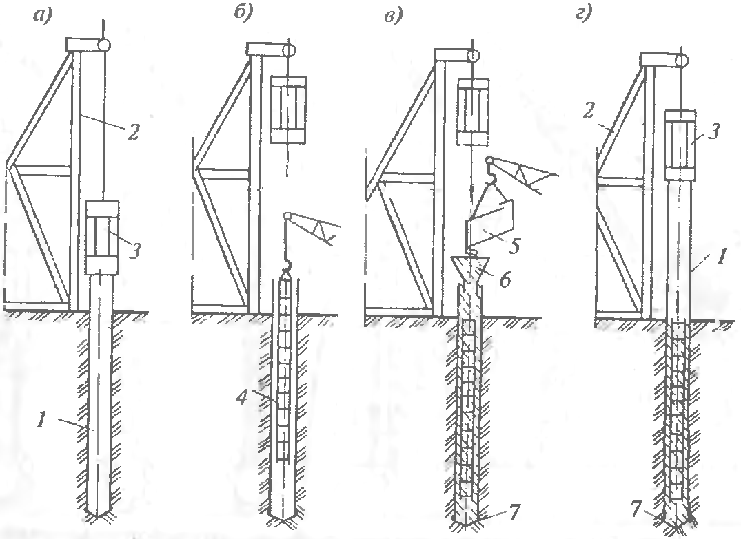
Figure: 6.21. Technological diagram of the device of rammed piles:
a - immersion of the casing; 6 - installation of the reinforcement cage; c - supply of concrete mixture into the pipe cavity; d - extraction of the casing with simultaneous compaction of the concrete mixture; ^ - casing pipe; 2 - pile driver; 3 - double action hammer; 4 - reinforcing cage; 5 - bucket with concrete mix; 6 - receiving funnel; 7 - cast iron shoe
This compaction of concrete in the casing is continued until the pipe is completely removed from the ground. If necessary, external vibrators are attached to the extracted casing pipe, which make it possible to better compact the upper layers of the concrete mixture. Frequency-reinforced piles can be made reinforced. Reinforcement is carried out by calculation, but in most cases, the reinforcement cage is used only in the upper part of the pile to connect with the reinforcement of a monolithic grillage. If the reinforcement is provided for the entire height of the pile, then the reinforcement cage is lowered into the casing before concreting begins.
Sand piles are the cheapest method of compacting soft soils. A steel casing pipe with a shoe is immersed in the ground using a vibratory pile driver (Fig. 6.22). Having reached the design mark, it is partially filled with sand, when the casing is raised due to the mass of sand, it is separated from the shoe, and with the help of a vibratory pile driver it is extracted to the surface, while the soil is compacted from vibration shakes. Additional and effective sealing can be achieved by spilling the well with water. Use pipes with a diameter of 32-50 cm; during extraction, there should always be a layer of sand with a height of 1.0-1.25 m in the pipe. The method is applicable for wells up to 7 m deep.
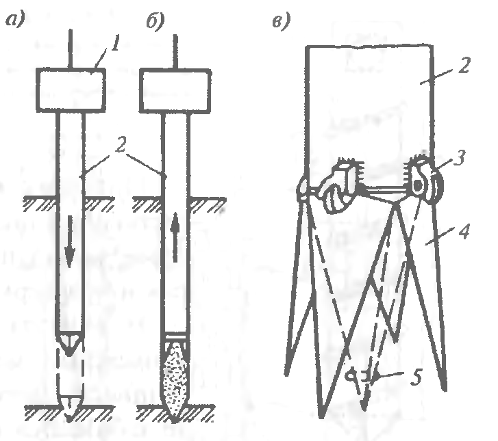
Figure: 6.22. Layout of the device of sand (soil) rammed piles:
a - immersion of the casing; b - pipe extraction; c - drop-down tip; I - vibrator; 2 - casing pipe; 3 - hinge; 4 - tip flap, 5 - ring
Ground concrete piles. Soil-concrete piles have been used, which are arranged using drilling rigs with a hollow drill rod having a mixing drill at the end with special blades cutting and simultaneously mixing the mixture. After drilling a well in soft sandy soils to the desired mark, a water-cement suspension (solution) is fed into the hollow rod under pressure from a mortar mixing plant. The drill rod slowly begins to rise upward with reverse rotation, the soil is saturated with cement mortar and is additionally compacted with a drill. The result is a sand-cement pile fabricated on site without excavation.
Screw-on piles. Often, pits for buried structures have to be arranged near existing buildings. Driving piles and sheet piles can lead to their deformation due to the resulting dynamic effects. When installing bored piles, where the casing is immersed with advance sampling of soil from the pipe cavity, the soil mass may leak from under the adjacent foundations, which can also lead to deformations of existing structures. The use of “wall-in-the-ground” methods or the use of mud for submerging the pipes increases the cost of the Project.
 Figure: 6.23. Diagram of a screw-in pile:
I - metal pipe, 2 - welding of winding with a pipe; 3 - winding from reinforcement with a diameter of 10-16 mm with a step of 200. 400 mm; 4 - cross-shaped blind or lost tip; 5 - crosspiece, b - metal disc
With these methods, the natural underground environment and its balance are disturbed, which can lead to undesirable results or to a serious increase in the cost of construction.
In cases of dense building, it is advisable to use the screw-on pile method. The essence of the method is that the metal pipe is not driven into the ground, but screwed up (Fig. 6.23). A narrow auger made of reinforcement with a diameter of 10..L 6 mm with a pitch of 200 ... 500 mm is wound onto the pipe at the factory. Depending on soil conditions, the pipe can be equipped with a plug with rippers, blind or loose, allowing, if necessary, to prevent water from entering the pipe body. When the pipe is screwed in, the surrounding soil is partially compacted, about 15 ... 25% of it is squeezed out.
If the pipe in the lower part is deaf, then after screwing to the design mark, a reinforcing cage is inserted into it and it is filled with concrete mixture. For pipes with a lost tip, a reinforcing cage is inserted into it, the pipe is filled with concrete, in the process of concrete setting, the pipe is unscrewed, a shoe remains in the ground, on which the reinforced concrete bored pile rests. With especially dense soils, it is possible to pre-drill a well to a slightly shallower depth (up to 1 m) and the diameter of the well should be less than the diameter of the pipe. The diameter of the screwed pipes is 300 ... 500 mm, the length is from 4 to 20 m. It is important that the technology allows to carry out work near existing buildings at a height of 5 floors at a distance of about 40 cm, at a higher height - about 70 cm.

Figure: 6.24. Technological diagram of the device of bored piles with a diameter of 2 ... 3.5 m:
a - installation of a drilling rig; 6 - well drilling; c - face cleaning; d - installation of the reinforcement cage; d - installation of concrete pipes; f - pile concreting, I - drilling rig; 2 - casing pipe; 3 - grab bucket; 4 - reinforcing cage, 5 - concrete pipe
In recent years, foundations have become widespread in the form of powerful deep-lying supports with a high bearing capacity. constructed with the help of special machines (Fig. 6.24). The excavation is carried out using a grab bucket inside the sinking casing. During excavation, the lower end of the pipe should be below the bottom of the well. The face is cleaned with a grab bucket. After installing the reinforcement cage in the well, concreting is carried out using the method of vertically moving pipe; the deepening of the concrete-lithic pipe into the concrete mixture must be at least 1 m.


