Under certain conditions, a loss of stability of a part of the soil massif may occur, accompanied by the destruction of structures interacting with it. This is due to the formation of some areas in the massif, where the ratio between the acting stresses becomes such that the strength of the soil is exhausted.
The assessment of the stability of the soil massif is based on the analysis of stresses arising in them from their own weight and the designed structure, and comparisons with their limiting values.
The condition of limiting equilibrium at a point of the soil massif is characterized by the following expressions of the theory of limiting equilibrium:
For sand (4.1)
For clay soil 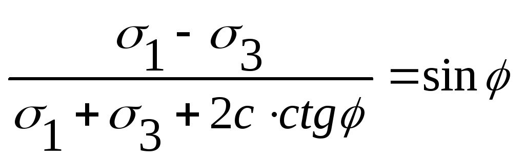 (4.2)
(4.2)
These expressions make it possible to estimate the stress state of the soil, i.e. to establish whether the soil is in a pre-limiting or limiting state, and, consequently, how stable the massif is.
The limiting state of the soil corresponds to the point in Fig. 4.1а, where the sediment S goes to infinity, i.e. the theory of limiting equilibrium examines only the stressed state of the soil massif and does not make it possible to determine the deformations developing in it.

4.1. Critical loads on foundation soils. Stressed state phases of soil foundations
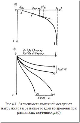
Consider a dependency graph  in fig. 4.1, a.
For cohesive soil, the initial section of the graph Oa will be almost horizontal, the length of this section will be determined by the value  structural strength of the soil, and deformation is elastic.
With increasing pressure (section ab) the sediment increases, the compaction process develops due to a decrease in the porosity of the soil. Dependence  is close to linear, precipitation tends to a constant value (4.1, b). The limiting state is not formed at any point of the base. The greatest stress limiting this area is called initial critical load
p beginning cr. , and the load change from 0 to p beginning cr. characterizes soil compaction phase.
is close to linear, precipitation tends to a constant value (4.1, b). The limiting state is not formed at any point of the base. The greatest stress limiting this area is called initial critical load
p beginning cr. , and the load change from 0 to p beginning cr. characterizes soil compaction phase.
When the pressure under the base of the foundation changes from 0 to p beginning cr. at no point of the base does a limiting state arise, i.e. only soil compaction occurs, which is absolutely safe for the base.
P  with a further increase in the load (section bw Figure 4.1, a) at points located under the edges of the foundation, shear stresses along some areas become equal to their limiting values. As the load increases, these points are combined into zones, the sizes of which increase. Shear deformations of a plastic nature appear. Dependency graph
  deviates more and more from the linear. Plot bw are called phase shifts... The end of this phase corresponds r and , called the limiting critical load, at which closed regions of limiting equilibrium are formed at the base, and soil stability is lost, i.e. complete exhaustion of the bearing capacity.
Depending on the depth of the foundation base d/ b the outlines of areas of limiting equilibrium have a different character (Fig. 4.2).
Loads corresponding p beginning cr. and r and called critical loads, they are determined by the methods of the theory of limiting equilibrium.
4.1.1. Initial critical load
The initial critical load corresponds to the case when a limit state occurs at the base under the foot of the foundation at a single point under the face of the foundation.
Choose a point at the base M (fig. 4.3) and define such a contact voltage r, at which at this point the limiting stress state arises.
In the model of a linearly deformable medium, the total stresses at point M are defined as
Let us write down the ratio for the depth of the lowest point at which the limiting state from the foot of the foundation is possible.
By definition, for p start cr z max \u003d 0. Then, at a single point of the base under the face of the foundation, the condition of limit equilibrium will be satisfied:
A foundation designed so that the stress under its sole does not exceed the initial critical load ( p<p beginning cr.), will be in a completely safe state. However, as practice has shown, the base soils will have a significant reserve of bearing capacity.
First critical ground load (ultimate ground load)
Puzyrevsky determined the first critical load for a cohesive soil, and Gersevanov for an incoherent one.

Р - evenly distributed load
g - lateral surcharge (γ - specific gravity of the soil, h \u003d d - depth of the loaded surface)
z is the depth of the point under consideration below the plane of the load application.
z max is the maximum value of the shear zones.
2β - angle of view
![]() - the equation of limiting equilibrium
- the equation of limiting equilibrium
The task is to determine such a load P 1 at which shear zones (zones of limiting equilibria) only originate under the loaded surface.
Since with a strip load (plane problem) the tangential stresses will be greatest at the edges of the load, it is natural to expect the nucleation of zones of limiting equilibrium in these places with increasing load. Suppose that there is a continuous load of intensity q.
with in - dead weight
![]()
![]()
Since point M is located in the shear zone, where the soil is in a plastic state and the pressure in all directions is the same, we take an additional assumption about the hydrostatic distribution of pressures from the soil's own weight.
![]()
2β - angle of visibility from point M

We substitute σ1 and σ3 in the equation of limiting equilibrium:
From this equation we express z (the depth of the location of the point M within the shear zone).
For the first critical load, it is necessary to fulfill the requirement that the shear zones have point dimensions. This condition will be fulfilled if the maximum size of the shear zone z max \u003d 0. Z max is obtained by examining the function z for the maximum. In this case, it is necessary to find the first derivative equal to 0, determine those variables that would correspond to z max and substitute them in z.
 - Puzyrevsky formula
Standard ground pressure. Estimated soil pressure of the foundation.

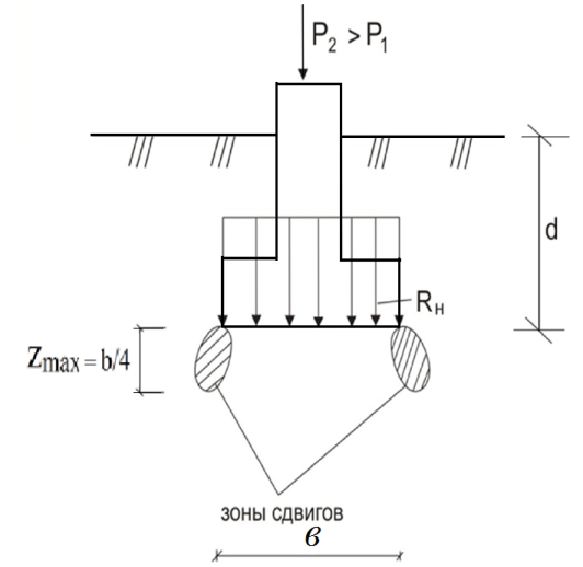

z max is the maximum value of the shear zones (its maximum value \u003d b / 4).
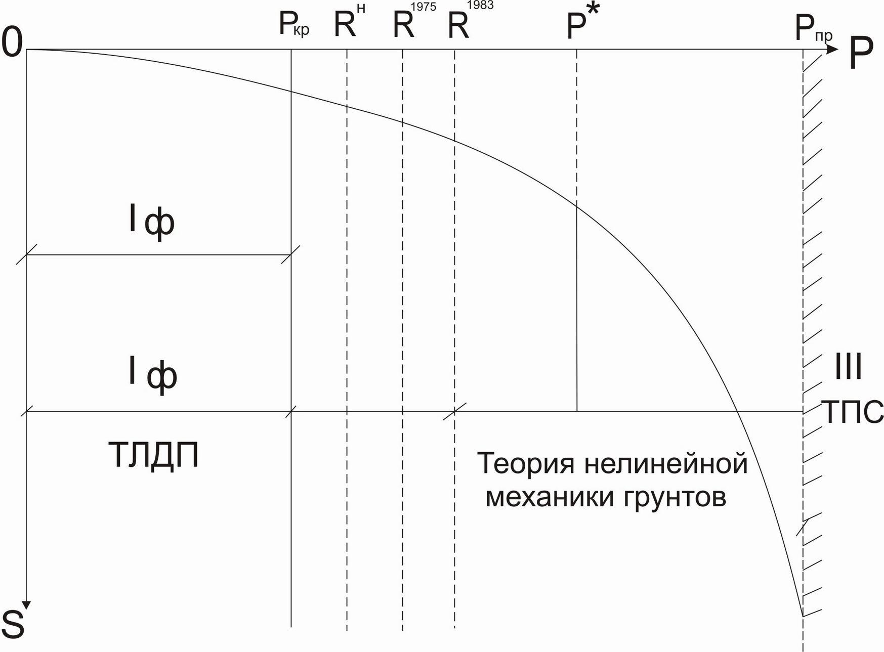
Until 1962, when calculating soil foundations, it was assumed that the actual average pressure along the base of the foundation p should not exceed the first critical load P 1. (p ≤ P 1). In 1962, the first SNiP was issued.
P cr -\u003e A cr -\u003e S calc.
The criterion was the actual observation of precipitation S fact. The actual precipitation was much less than the calculated S fact<
R n - was obtained as the first critical load, but not at z \u003d 0, but at z \u003d b / 4.
Р 1, at z \u003d 0 - there are no plastic zones.
R n, at z \u003d b / 4 - there are plastic zones.
R n\u003e P cr, P Observations continued and in 1975 another SNiP came out - R - calculated ground pressure: During observations, the pressure was increased due to the coefficients m 1 - coefficient depending on the type of foundation soil m 2 - coefficient depending on the type of soil and the structural scheme of the building (structure) k n - safety factor These expressions make it possible to estimate the stress state of the soil, i.e. to establish whether the soil is in a pre-limiting or limiting state, and, consequently, how stable the massif is. The limiting state of the soil corresponds to the point in Fig. 4.1а, where the sediment S goes to infinity, i.e. the theory of limiting equilibrium examines only the stressed state of the soil massif and does not make it possible to determine the deformations developing in it. Consider the graph of dependence in Fig. 4.1, a. For cohesive soil, the initial section of the graph Oa will be almost horizontal, the length of this section will be determined by the value of the structural strength of the soil, and the deformation has an elastic character. With increasing pressure (section ab) the sediment increases, the compaction process develops due to a decrease in the porosity of the soil. The dependence is close to linear, precipitation tends to a constant value (4.1, b). The limiting state is not formed at any point of the base. The greatest stress limiting this area is called initial critical load p beginning cr. , and the load change from 0 to p beginning cr. characterizes soil compaction phase. When the pressure under the base of the foundation changes from 0 to p beginning cr. at no point of the base does a limiting state arise, i.e. only soil compaction occurs, which is absolutely safe for the base. With a further increase in the load (section bw Figure 4.1, a) at points located under the edges of the foundation, the shear stresses along some sites become equal to their limiting values. As the load increases, these points are combined into zones, the sizes of which increase. Shear deformations of a plastic nature appear. The dependence graph deviates more and more from linear. Plot bw are called phase shifts... The end of this phase corresponds p and, called the limiting critical load, at which closed regions of limiting equilibrium are formed at the base, and soil stability is lost, i.e. complete exhaustion of the bearing capacity. Depending on the depth of the foundation base d/
b the outlines of areas of limiting equilibrium have a different character (Fig. 4.2). Loads corresponding p beginning cr. and p andcalled critical loads, they are determined by the methods of the theory of limiting equilibrium. The initial critical load corresponds to the case when a limit state occurs at the base under the foot of the foundation at a single point under the face of the foundation. Choose a point at the base M (fig. 4.3) and define such a contact voltage r, at which at this point the limiting stress state arises. In the model of a linearly deformable medium, the total stresses at point M are defined as Let us write down the ratio for the depth of the lowest point at which the limiting state from the basement base is possible. By definition, for p start cr z max \u003d 0. Then, at a single point of the foundation under the face of the foundation, the condition of limiting equilibrium will be satisfied: A foundation designed so that the stress under its sole does not exceed the initial critical load ( pp start cr.), will be in a completely safe state. However, as practice has shown, the foundation soils will have a significant reserve of bearing capacity. If we allow under the sole of a centrally loaded foundation with a width b development of zones of extreme equilibrium to depth, then load bearing capacity the foundation remains secured. In this case, precipitation decays in time and tends to a constant value, and the dependence turns out to be quite close to linear. Therefore, under these conditions, for calculating the deformation of the base, the formulas of the theory of linear deformation of soils can be used. Base soil resistance R n corresponds to the highest average compressive stress under the base of the foundation at which along the base of the foundation, the development of the limiting state regions is allowed to a depth equal to b/4
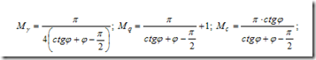
. here M γ , M q, M c- some functions of the angle φ. The values \u200b\u200bof these coefficients are given in SNiP 2.02.01-83 *. Further studies made it possible to push even further the practical limit of the average stress under the base of the foundation, where the calculation of the settlement taking into account the linear deformation of the soils of the foundations is also permissible. This value, according to SNiP 2.02.01-83 *, was named design soil resistance R
(4.11). In this case, formula (4.9) has a slightly more complex form (accounting for basements, accounting for soil heterogeneity, etc.) and will be considered in the course "Foundations and Foundations".![]()
4.1. Critical loads on foundation soils. Stressed state phases of soil foundations

4.1.2. Standard resistance and design pressure
4.1.3. Ultimate critical load
corresponds to the stress under the base of the foundation, at which the bearing capacity of the base soils is exhausted (Fig. 4.1), which leads to the squeezing out of the soil from under the foundation and its huge settlement (Fig. 4.2). Load corresponding p and leads to a complete loss of stability of the foundation soil and is absolutely unacceptable for the designed structure.
L. Prandl, K. Tertsachi, V. V. Sokolovsky, M. V. Malyshev were engaged in solving this problem.
In fig. 4.3. one (left) region of limiting equilibrium and two "families" of slip lines are presented, which form slip rhombs with certain angles of inclination of the lines.

The most complete solution to this problem was obtained in 1952 by V.V. Sokolovsky.
|
|

where N γ , N q, N c= f(φ , δ ) - tabulated dimensionless coefficients.
The above solutions are valid for relatively shallow depths of the foundations and a homogeneous structure of the foundation, therefore, in practical calculations, engineering methods are usually used, to one degree or another taking into account the rigorous solutions of the theory of limiting equilibrium.
4.2. Practical methods for calculating the bearing capacity and stability of foundations
Principles of calculating the foundations of foundations for the I limit state (for the strength and bearing capacity of soils).
According to SNiP 2.02.01-83 *, the bearing capacity of the base is considered to be ensured if the following conditions are met:
|
|
F - resultant of the design force (load) applied to the base;
F u - force of ultimate resistance (resultant of ultimate load);
γ from - coefficient of working conditions, depending on the type of soil.
γ n - the coefficient of reliability for the purpose of the structure.
4.3. Stability of slopes and slopes
A slope is an artificially created surface that limits a natural soil massif, excavation or embankment. Slopes are formed during the construction of various types of embankments (dams, earth dams, etc.) and excavations (pits, trenches, canals, etc.). Slope is a slope formed by a natural way and bounding an array of natural soil.
The main reasons for the loss of stability of slopes and slopes are:
The device of an unacceptably steep slope or undercutting of a slope that is in a state close to the limit;
Increase in external load (erection of structures, storage of materials on the slope or near its edge);
Change in internal forces (change in the specific gravity of the soil when changing its moisture content);
Incorrect assignment of the calculated characteristics of the strength of the soil or a decrease in its shear resistance due to an increase in moisture and other reasons;
Manifestation of hydrodynamic pressure, seismic forces, various kinds of dynamic influences (traffic, pile driving, etc.).
4.3.1. The concept of the safety factor of slopes and slopes
The stability factor is often taken as:
 , (4.13)
where φ, s - the calculated values \u200b\u200bof the characteristics of the soil shear resistance adopted in the project; φ ', s' - the same, corresponding to the limiting state of the slope or slope.
The stability of a slope or slope is considered to be ensured if, where \u003d 1.1 ... 1.3 is the standard stability coefficient.
Groups of methods used to calculate the stability of slopes and slopes:
Elementary solutions;
Strict decisions;
Engineering methods;
Numerical methods.
At the same time, two types of tasks are analyzed:
one). Evaluating the stability of a slope or slope of a given steepness
2). Determination of the optimal slope or slope steepness for a given.
4.4. The simplest methods for calculating stability
4.4.1. Stability of slopes in ideally loose soils (ϕ ≠ 0; с \u003d 0)
There is a slope with an angle α , for a given φ for sand composing the slope (Figure 4.4, a). Consider the equilibrium of a particle lying freely on the surface of the slope: the soil has only internal friction, then stability will be ensured if T≤T '.

Given the weight of a particle P and considering that the coefficient of internal friction of soils, we get;
at α=φ in ideally loose soils, the angle of repose - α is equal to the angle of internal friction of the soil.
4.4.2. Taking into account the influence of filtration forces
If the groundwater level is above the bottom of the slope, a seepage flow emerges on its surface, which leads to a decrease in the stability of the slope.
In this case, when considering the equilibrium of a particle, it is necessary to add the hydrodynamic component D.
The hydraulic gradient at the outlet point of the flow is:
γ w - specific gravity of water;
n - porosity.
Considering that the weight of a unit volume of soil P=γ Vwhere V=1.
The limiting state equation will be written as:
The angle of the slope at a given standard coefficient of stability:
4.4.3. Stability of a vertical slope in perfectly cohesive soils (ϕ \u003d 0; s ≠ 0)
If the height of the slope, made up of cohesive soils, does not exceed the limiting value h 0, then the cohesive soil can hold a vertical slope.
The most unfavorable stress state occurs at the foot of the slope at point A (Figure 4.1, c) It is here that the state of limiting equilibrium begins to form.
The maximum principal stress at this point is equal to the natural one, i.e. ... Since the slope is limited by the free vertical surface, the minimum principal stress at point A is zero, i.e. ...
The limiting equilibrium condition has the form:
Taking into account that here φ \u003d 0 (by the condition of the problem), and also substituting here σ 1 and σ 3, after the transformation we will have: and
![]()
It is assumed that the loss of stability of the slope (slope) can occur as a result of the rotation of the section of the soil massif relative to a certain center ABOUT(Fig. 4.5, a) .
The essence of the method is to analyze the stability of the slope against shear along a number of possible sliding surfaces, represented by an arc of a circle with a radius r and center incl. ABOUT.
The section of the soil massif, limited by the free surface and the sliding surface, is divided by vertical lines into nelements in such a way that it is possible to take the base of each compartment flat, and the strength characteristics are constant.
A shifting array is considered as a non-deformable compartment, all points of which participate in the general motion.
.Usually, a series of such calculations is carried out for different positions of the centers of rotation and values \u200b\u200bof r.
Most often, the most hazardous sliding surface passes through the lowest point of the slope (slope). In addition to weak soils with minimum φ and from.
4.5.2. Measures to improve the stability of slopes and slopes
One of the most effective ways to increase the stability of slopes and slopes is to flatten them or create a stepped profile with the formation of horizontal areas (berms) along the slope height.
With a relatively low slope height, it is effective to load the sole in its lower part or to construct a retaining wall that supports the slope. Securing the surface of the slope can be carried out by paving with stone, matting, laying concrete slabs.
The most important measure is the regulation of the hydrogeological regime of the slope or slope. Installation of ditches for interception of surface waters, water diversion from berms, drainage arrangement.
Constructive measures such as cutting through a potentially unstable soil mass with a system of driven or rammed piles, anchoring in interaction with retaining walls or pile structures.
4.6. Concepts about the interaction of soils with enclosing structures (resting pressure, active and passive pressure)
The enclosing structures are designed to keep the soil massifs behind them from collapse. Such structures include a retaining wall, as well as walls of basements and buried parts of a building, walls of underground structures, etc. Distinguish between massive (or gravitational) and thin-walled retaining walls (Fig. 4.6). By the nature of the work, they are divided into rigid and flexible (sheet piling walls).
Coef. lateral pressure; ν - coefficient. Poisson.
When the wall is displaced under the action of pressure away from the backfill by an amount u a (Figure 4.7, a) in the backfill soil, an area of \u200b\u200bsoil collapse is formed, the boundary of which is called the sliding surface, and the area itself is the collapse prism. The pressure transmitted by the collapse prism to the face of the wall is called active pressure, and its resultant is denoted E and.
When the wall is displaced towards the ground under the action of any forces in the backfill, sliding surfaces are also formed, with a displacement of + u p a soil bulging prism is formed (Figure 4.7, c). In this case, the reaction of the soil reaches its maximum value and corresponds to the passive pressure (rebound) of the soil, the resultant of which is denoted E P.
4.6.1. Determination of active pressure on the vertical face of the wall for loose soil and cohesive soil, taking into account the surcharge on the backfill surface E
Passive pressure ordinate values \u200b\u200bat depth z from the fill surface at the origin at point 0 ':
At the same depth from the filling surface, the ordinate of the passive pressure plot is significantly greater than the ordinate of the active pressure plot. Bulging prism width l’ =htg (45 ° + φ / 2).
The value of the first load will be called the initial critical load, which is still completely safe in the foundations of structures, since until it is reached, the soil will always be in the compaction phase.
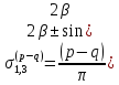
Consider the action of an equal distribution load ron the strip wide. b in the presence of a lateral load. q \u003d γhwhere γ -soil density, h- the depth of the laying of the outer surface. Vertical compressive stresses (pressure) from self-weight gr. With a horizontal limiting surface σ 1gr \u003d γ (h + z), z- the depth of the location of the considered point below the plane of the load application. The task is to determine such a value of the load start Pcr, at which the shear zones (near-side equilibrium zones) are only generated under the heated surface. Since, with a strip-like load, the shear stresses will be greatest at the edges of the load, that is, it is natural to expect in these places with the age and the growth of the zone of equilibrium. Let us accept the condition of limiting equilibrium. σ 1 - σ 2 \u003d 2sinφ (((σ 1 + σ 2) / 2 + p e) Let us find the main stresses, taking into account the action of the intrinsic weight gr. As a continuous load:
σ 1 \u003d (p-γh) * (α + sinα) / π + γ (h + r)
σ 2 \u003d (p-γh) * (α-sinα) / π + γ (h + z).
Substitute expressions σ 1and σ 2 into the condition of the limiting equal-i and take into account p e\u003d c ctqφ, we get: (p-γh) * sinα / π - sinφ ((p-γh) / π * α + γh + γz) \u003d c ctqφ... Receive express. you can raskat as Ur-e of the boundary-th region of the limiting equilibrium-i, z-as the ordinate of this region. z \u003d (p-γh) * ((cosα / sinφ) -α) / πγ -c / γ ctqφ-h. Find z maximum, dz / dα \u003d (p- γ h) * ((cosα / sinφ) -1) / π γ \u003d 0. Cosα \u003d sinφ or α \u003d π / 2-φ, sin (π / 2-φ) \u003d cosφ. Substituting the value, pcr \u003d π / ctqφ + φ-π / 2 ( γ zmak + yh + c ctqφ) + γ h. The standard pressure on group R is such a pressure at which, under the edges of the foundation, the zone of maximum equalization is not distributed at depth, more than z max \u003d b / 4.b-width of the foundation. If absolutely not at any point in the development of zones of limit equal-I under the bottom of the foundation, then we should put in the equation zmak \u003d 0. soil nadrkr. early Rcr \u003d π (γh + c ctqφ) / ctqφ + φ-π / 2This is the formula for the initial critical soil load.
The initial critical pressure on the foundation is the pressure value at which regions of the ultimate stress state arise in the foundation soil. At pressures lower than the initial critical values \u200b\u200bat all points of the foundation, the stress states are pre-limiting, which is completely safe for the foundations of structures. In this case, until the initial critical pressure is reached, the soil is in the compaction phase and the approach to its determination is demonstrated for the strip load on the soil.
To find the initial critical pressure, the values \u200b\u200bof the principal stresses σ1 and σ3 are determined taking into account the applied load P \u003d P0- q and, accordingly, the weight of the soil.
The vertical compressive stress (pressure) from the own weight of the soil at the point M (see Fig. 8.5, c), lying at a depth z from the base of the foundation, is determined from the expression
Substrate soils experience two types of pressure:
· Household sb, arising in soils under the influence of the weight of the overlying layers;
· Additional s arising under the influence of loads from foundations.
In the general case, the ordinates of the pressure diagram under the sole of a rigid foundation, under the action of a vertical load, are determined by the formula:
If, in addition to the vertical load, a horizontal load or a tipping moment acts on the foundation, then in this case the tilting moment created by the horizontal load is found, and formula (6) will be written as:
Figure: Scheme for calculating pressures under the sole of rigid foundations.
Figure: Soil pressure plots under the sole:
a - for clayey soils; b - with sandy soils; in - with eccentric load, when e< b/6; г–при внецентренной нагрузке, когда е = b/6; д–при внецентренной нагрузке, когда е > b / 6.
as the foundation is loaded, two critical loads are observed: the load corresponding to the beginning of the occurrence of shear zones in the soil and the end of the compaction phase, and the load at which continuous areas of ultimate equilibrium are formed under the loaded foundation, the foundation soils lose stability and its bearing capacity is exhausted.
The initial critical load corresponds to the case when a limit state occurs at the base under the foot of the foundation. This load is still safe in the foundations of the structure, since before reaching it, the soil is always in the compaction phase. At loads lower than the initial critical, at all points of the base, the stress states are prelimit and the deformability of the soil obeys Hooke's law. Therefore, to determine the initial critical load, solutions of problems of the theory of elasticity can be used
It should be borne in mind that the initial critical load corresponds to the proportionality limit between stresses and deformations of the soil, and a pressure equal to or less than the initial critical pressure is considered safe.
No. 3 EMTIKHAN TICKET / EXAMINATION TICKET
1. Structural bonds between soil particles
Structure- this is the size, shape, quantitative ratio of the particles composing the soil and the nature of the connections between them, due to the entire prehistory of the soil. The bonds between particles and particle aggregates are called structural links . Due to the high strength of the particles themselves, the bonds between the particles determine the deformability and strength of the soil.
Non-rocky soils by the nature of structural bonds are divided into liaison and incoherent (loose ). Cohesive soils include silty-clayey soils; to incoherent - coarse and sandy soils. Cohesive soils are capable of accepting low tensile stresses; non-cohesive soils do not perceive tensile stresses.
Resistance to the mutual movement of particles of loose soils is due to the frictional forces of the contacting surfaces. This mechanism of interaction between particles of loose soil is called internal friction of the soil.
Structural bonds in clayey soils are of a much more complex nature and are determined by electromolecular forces of interaction between particles, as well as particles and ions in pore water. They determine the cohesion of clay soils. The intensity of these bonds depends on the distance between particles, charges on their surface, composition and content of ions in pore water.
Clay soil with very high moisture content is essentially a finely dispersed suspension in fluidcondition. In this case, there are practically no bonds between particles. With an increase in the concentration of the dispersed phase (decrease in humidity W)the suspension thickens, as a result of which the distance between the solid particles decreases. When clay particles come closer to a distance of the order of several hundred and thousands of angstroms, the forces of molecular attraction (van der Waals forces) appear between them. These forces are due to the interaction of surface molecules of solid particles as a result of periodic oscillations of the electron shells and atomic nuclei, at which instantaneous dipoles are formed. The repulsive forces between their like-charged hydration-ion shells prevent the particles from approaching; therefore, molecular bonds are realized in the corners and on the edges of the particles, where the shells are thinner.
Molecular forces play a significant role in the formation of the strength properties of clay soils at the initial stages of lithogenesis (transformation into rock), at the stage of sedimentation (sediment formation), during coagulation and sediment formation, as well as at the stage of diagenesis (transformation of sediments into solid rocks).
The repulsive forces of similarly charged surfaces of particles and diffuse layers of bound water begin to hinder further approach of soil particles, therefore, further approach of particles is possible only when additional efforts are expended, for example, as a result of soil compaction under load or drying it out. Compaction of the soil leads to the convergence of particles and strengthening of bonds, while ionic-electrostatic forces become significant. The determining factor for their formation is the presence of exchangeable cations in the diffuse layer. If one approaches another charged particle, then the cations of the diffuse layer will interact simultaneously with two particles and an ion-electrostatic bond is formed between the latter (Fig. 1.4). This bond manifests itself at distances between particles of several tens of angstroms, but its strength is several orders of magnitude higher than the strength of bonds caused by van der Waals forces.
According to the classification developed by academician P.A. Rebinder, professors N.Ya.Denisov, N.A. Maslov and others, you noted
the same structural links relate to water-colloidal . The presence of hydration shells of particles gives these bonds a mobile, reversible character. They are preserved during deformation: crushing a wet piece of clay does not violate its overall cohesion. The state of clay soil, in which it is able, under the influence of external forces, to change its shape without breaking the continuity and to maintain the newly obtained shape for a long time is called plastic .
Drying of the soil leads to a decrease in the thickness of the hydrate-ionic shells and an increase in the water-colloidal bonds between the particles. On the contrary, an increase in soil moisture and saturation of diffuse layers has a wedging effect on soil particles, which leads to a weakening of water-colloidal bonds and an increase in soil mobility.
A small amount of water in the soil corresponds to a very high strength of water-colloidal bonds; clayey soil at low moisture values \u200b\u200bis in solid condition.
Along with water-colloidal bonds in soils that retain their natural structure, there may be cementation communication. They are formed during a long geological period of the formation and existence of soils due to the precipitation of salts dissolved in pore water, cementing individual solid particles with each other.
They can be less strong and water-resistant bonds formed by gypsum, calcite, and more durable and water-resistant, such as oxides of iron, silicon, etc. In contrast to water-colloidal, cementation bonds are rigid and irreversible, not restored when the natural structure of the soil is destroyed ...
Mutual spatial arrangement of particles in the soil (texture) depends on the conditions of their deposition: whether sediment is formed in air or water, stationary or flowing water, etc.
During the deposition of relatively heavy sandy and dusty particles, for which gravitational forces prevail over the electromolecular forces of interaction, a granular system of particles is formed (Fig. 1.5, a).
At the initial stage of sedimentation of clay particles in still water, a dispersed (dispersed) system is formed (Fig. 1.5, b), the particles are, as it were, in a suspended state.
Over time, clay particles can contact each other and form a flocculation system for the arrangement of particles (Fig. 1.5, c). Dispersed and flocculation systems are typical for freshly formed clayey soils (loose, highly compressible silts and silty soils).
As a result of the action of the weight of the overlying sediment layers, their lower layers are compacted, and at the same time a reorientation of particles occurs in them. They get an ordered, oriented system of mutual arrangement (Fig. 1.5, d).
The natural structure of soils, their composition and condition mainly determine the deformation and strength properties of soils and their work as foundations and environments for structures, and a very important characteristic will be the structural strength of soils and the stability of the structural bonds of waters under the influence of external influences.
2 Protection of foundation pits from flooding
| · To protect pits from flooding, the following groups of methods are used: - dewatering; - anti-filtration curtains; - a combination of the first two methods. · The choice of this or that group of methods depends on: - the type of groundwater; - UPV (UGV); - soil properties; - features of their bedding; - the depth, size and shape of the pit in the plan; - other factors. · In all cases, no matter what method we choose, it is necessary to exclude the violation of the natural structure of the soil at the base, to ensure the stability of the pit slopes and the safety of closely located buildings. → Water lowering is carried out using: - deep water lowering; - open drainage 1. Open drainage - the easiest way. Water is pumped out by pumps directly from the pit. More precisely, from a network of grooves with a depth of 0.3 ... 0.6 m arranged at the bottom of the pit, along which water is diverted into a pit (sump), from where it is systematically pumped out by pumps. - Open drainage is used only in poorly eroded soils and rocks (fractured rocks, pebbles, gravel, coarse sands), as well as where there is little direct water input. 2. Deep dewatering eliminates the seepage of groundwater through the slopes and the bottom of the pit. It consists in artificially lowering the groundwater level in the area of \u200b\u200bthe pit. It is carried out with the help of: - wellpoints; or - pumping water from deep tubular wells (in the case of a large inflow of water). : Wellpoint consists of a steel pipe d \u003d 38 ... 50 mm, the lower end has a filtering device through which water is sucked in and pumped out. The filter is designed in such a way that it is ensured that particles cannot be carried away. Arising from the movement of water (from the bottom of the pit to the IFU) Fig. 14.9 a, hydrodynamic pressure contributes to the compaction of soils and ... - to improve their structural properties. · Light wellpoints (LIU) are used to lower the groundwater level to a depth of 4 ... 5 m in the sands. At great depths, wellpoints are placed in several tiers (Fig. 14.9.b) or special ejector wellpoints are used (water-jet pumps that create a vacuum around the filter element, which helps to increase suction), which makes it possible to lower the GWL to a depth of 25 m. - LIU is used in sands large, medium-sized and small - Ejector wellpoints, as more powerful, are used in silty sands and loamy sands with k f\u003e 0.1 m / day. Bitumization consists in feeding (injection) into the soil with fracturing (rocky fractured rocks) with a large inflow of water heated to a liquid state of bitumen. Due to this, a solid waterproof wall is formed. Along with the injection of bitumen, cement mortar or synthetic resins are used. The injection of any material into the soil in order to eliminate its water permeability is called backfill.End of form |
3 Soil pressures on enclosing structures
Ground pressureon the enclosing surface depends on many factors:
- method and sequence of backfilling;
- natural and artificial compaction;
- physical and mechanical properties of soil;
- accidental or systematic ground shaking;
- sediment and wall displacements under its own weight, soil pressure;
- type of adjacent structures.
All this greatly complicates the task of determining the soil pressure. There are theories for determining soil pressure, using prerequisites that allow solving the problem with varying degrees of accuracy. Note that this problem is solved in a flat setting.
Coulomb's theory, proposed in 1776, is based on the consideration of the limiting equilibrium of a soil prism, limited by rectilinear planes of collapse (bulging). A more rigorous solution to the limiting equilibrium shows that the actual outline of these sliding surfaces is curvilinear. However, the values \u200b\u200bof active soil pressure on vertical or close to vertical, rigid, smooth and rough walls, determined by Coulomb and by the exact method, differ by 2-3%, which undoubtedly can be considered a satisfactory result from an engineering point of view. The passive soil pressure depends very significantly on the friction of the soil against the wall, which in real conditions always occurs. Taking into account the friction of the soil against the wall using the dependencies arising from the Coulomb theory gives at φ \u003d 15-20 ° a significant error in the direction of exaggeration in comparison with the existing solution. More accurate results gives the theory proposed by SV. Sokolovsky, built on the basis of the general theory of the limiting stress state of a granular medium. There are various interpretations of this theory, including the well-known graphic interpretation of S.S. Galushkevich.
Most engineering calculations use results obtained from the Coulomb theory; in cases where the results need to be refined, correction factors are used based on exact solutions and experimental data. There are the following types of lateral soil pressure:
- resting pressure (E a), also called natural (natural), acting in the case when the wall (enclosing surface) is stationary or the relative displacements of the soil and structure are small ( fig. 10.7);
- active pressure ( E a) arising from significant displacements of the structure in the direction of pressure and the formation of sliding planes in the soil, corresponding to its ultimate equilibrium ( fig. 10.8). ABS - base of the collapse prism, the height of the prism - 1 m;
- passive pressure ( E p), appearing with significant displacements of the structure in the direction opposite to the direction of pressure and accompanied by the beginning of "soil uplift" ( fig. 10.9). ABS - base of the bulging prism, prism height -1m;
- additional reactive pressure ( Е r), which is formed when the structure moves towards the ground (in the direction opposite to the pressure), but does not cause "soil uplift".
The interaction of the enclosing structure with the soil mass is complex and depends on the rigidity of the structure, on its displacements and deflections. With an absolutely immobile state of the soil mass behind the retaining wall, the so-called resting pressure... When the wall is displaced from the soil array behind the retaining wall, active pressure... When the wall moves to the soil mass held by it, it is realized passive pressure... Graphically, these three types of pressure are represented as a dependence
No. 4 EMTIKHAN TICKET / EXAMINATION TICKET
1. Geological structure of foundations
Usually, several types of soil are located at the base. In this case, in addition to assessing the properties of each soil, an equally important task arises - schematization of the geological structure of the foundation, i.e. highlighting the boundaries between them. Engineering-geological elements form geological bodies in the soil massif (Fig.)
A layer is called an internally homogeneous geological body, bounded within the area under consideration by two non-intersecting surfaces: the bottom and the top. The distance between the base and the roof is called the thickness of the layer. A lens is an internally homogeneous geological body bounded within the area under consideration by a closed surface. If a geological body enters from one side into a geological section and ends in it, then this is called layer wedging out. A very thin geological body, bounded by two non-intersecting surfaces, is called an interlayer. Residential is called an internally homogeneous geological body, extended and intersecting layers. The zone is called the area of \u200b\u200btransition from soils with some properties to soils with other properties.
When determining the structure of the soil, it must be remembered that the structure of the soil is determined by interpolation of data obtained along individual verticals (wells, geological exploration data), and the reliability of the obtained data will depend on the number of verticals, as well as the distances between them.
Structurally unstable soils are soils that in their natural state have structural bonds, which, under certain influences, reduce their strength or completely collapse. These effects can consist in a significant change in temperature, humidity, and the application of dynamic forces.
Structurally unstable soils include soils: loess, the structure of which is disturbed when soaked under load; frozen and permafrost, the structure of which is disturbed during thawing; loose sands, sharply compacted under dynamic influences; silts and sensitive clays, the deformation and strength properties of which change dramatically when their natural structure is disturbed. Also, special soils include: swelling soils, which, when moistened, can significantly increase in volume even under load; peat and peat soils with very high compressibility and low strength; rocky and semi-rocky soils, which, as a rule, have high strength and low deformability.
Failure to take into account the specific properties of these soils can lead to a violation of the stability of buildings and structures, to their excessive deformations.
Structurally unstable soils are often referred to as regional soil types because these soils are often grouped within certain geographic and climatic zones, in certain regions of the country, i.e. prevail in some regions and may be practically absent in others.
The features of soil deformation are manifested in different ways in different types soils and significantly depend on the condition of the soil and the intensity of the acting loads.
Monolithic rocky soils under loads arising from the construction of industrial and civil structures can usually be considered as practically non-deformable bodies. However, fractured rock and collapsible rock soil have some deformability. Destroyed structural bonds in rocky soils are not restored over time.
2 Protection of foundations from groundwater and moisture
Penetrating into building construction moisture is a major cause of their destruction. Protection against water penetration (waterproofing) is an important factor in the safety and durability of buildings. When high level standing groundwater there is a danger of their penetration into basements, leaks and damp spots on the walls.
Capillary moisture rising through the pores in the basement and basement array from wet soil can also spread into the masonry of the walls of the lower floors. In case of aggressiveness of groundwater, the materials of the foundation and underground parts buildings can collapse. To protect the building from groundwater, measures are provided to combat the movement of groundwater and the penetration of atmospheric precipitation into the basement soil and arrange protective waterproofing against the penetration of ground moisture into the building structure.
In order to prevent the penetration of rain and melt water into the underground parts of the building, the surface of the building site is planned, creating the necessary slope to divert surface water from the building. Around the building along the outer walls, a blind area is made of dense waterproof materials (asphalt, asphalt concrete, etc.). To protect against the penetration of ground moisture into the structure of a building, during new construction, external insulation of structures from the side of water is usually performed, and for old buildings, internal waterproofing is used in basements.
There are three types of waterproofing, corresponding to the types of water exposure - non-pressure, anti-pressure and anti-capillary. Non-pressure waterproofing is performed to protect against the temporary effects of moisture in atmospheric precipitation, seasonal top water, as well as in drained floors and ceilings. Anti-pressure waterproofing - to protect the enclosing structures (floors, walls, foundations) from hydrostatic groundwater backwater. Anti-capillary - for insulation of building walls in the zone of capillary rise of ground moisture.
The basement waterproofing device is determined by the nature of the water effect, the peculiarity of the drained structures and materials, as well as the functional requirements for the premises for operation, purpose and permissible humidity. This influences the choice of the type and material of insulation, determined by the required indicators for water permeability, water resistance, vapor permeability and durability. The capabilities of contractors, the season and the pace of work should also be taken into account when selecting waterproofing materials... Exist different methods waterproofing devices: basic - gluing, painting, coating, plastering, sheet (caisson) and clay, as well as special - injection, penetrating (penetration), geomembrane impregnating, suture, underwater, elimination of active leaks, etc.
3 Practical methods calculation of final deformations of foundations
Calculation of the sediment by the method of layer-by-layer summation.
This method (without the possibility of lateral expansion of the soil) is recommended by SNiP 2.02.01 - 83 and is the main one in calculating the settlement of foundations of industrial buildings and civil structures. The order of auxiliary constructions and the sequence of calculations in relation to settlement scheme on the picture.
First, the foundation is tied to the engineering-geological situation of the foundation, that is, its axis is aligned. With known loads from the structure, the average pressure on the base is determined along the base of the p. Then, according to the rules given in § 5.4, starting from the surface of the natural relief, a natural pressure diagram is plotted along the foundation axis. Knowing the natural pressure at the level of the foundation sole, additional vertical stress in the plane of the foundation sole is determined. In accordance with the above, on the same scale, a diagram of additional stresses is plotted along the foundation axis.
Having plotted the diagrams of natural pressure and additional stress, the lower boundary of the compressible strata is found. It is convenient to perform this operation graphically, for which the plot of natural pressure, reduced by 5 or 10 times (depending on the condition of limiting the compressible thickness), is combined with the plot of additional stresses. The point of intersection of the lines bounding these diagrams will determine the position of the lower boundary of the compressible thickness.
The compressible base thickness is divided into elementary layers so that the soil is homogeneous within each layer. Usually, the thickness of each elementary layer is taken to be no more than 0.5. Knowing the additional stress in the middle of each elementary layer, the compression of this layer is determined. The norms allow taking values \u200b\u200bof the dimensionless coefficient p equal to 0.8.
№ 5 EMTIKHAN TICKET / EXAMINATION TICKET
1. Deformability of soils
The deformability of clayey soils is mainly due to the mutual movement of solid soil particles. In coarse-grained soils, the main factors of deformability are the crushing of contacts and the destruction of solid particles under load. In sandy soils, both the processes of reorientation and mutual movement of particles and their destruction occur. Deformations are divided into volumetric and shape changes.
The volumetric compressibility of clay two-phase soils is possible only when water is squeezed out of the soil. Since the pores of the soil are small, the squeezing out of free water occurs slowly, and the process of deformation of the soil, depending on its volume, is often stretched for a long period of time. The increased viscosity of the cohesive water also slows down the deformation process (volumetric and shape change).
The process of deformation of clay soil in time is described by the theory of soil consolidation, some simplified provisions of which are set out in 12.3.
In sandy soils, deformation processes under the action of a static load proceed quickly, therefore, they are usually not considered in time.
In coarse-grained soils, the processes of crushing contacts, their destruction, rearrangement of the structure due to the destruction of individual grains, and redistribution of the load between particles, often, as in clay soils, occupy long time, although the mechanism of the process in time is different.
Since the soil consists of solid particles and pores, which are partially or completely filled with water, the following deformations occur under the action of an external load in the soil:
Mutual displacement of particles and particle aggregates with their denser repackaging;
Destruction of particles and their aggregates;
Squeezing water and air out of the pores of the soil;
Deformation of water films at the points of contact of soil particles;
Compression of air in closed soil pores;
Elastic deformation of mineral particles.
After removing the load, some deformations are restored. They are called elastic deformations... These are deformations of soil particles, films of bound water, elastic compression of trapped air bubbles and pore water. Such deformations of the soil, as a rule, are many times less than deformations due to shifts of soil particles, squeezing of water and air from pores, which are called residual, i.e. not recovering after unloading. As a result, permanent deformations lead to soil compaction.
2 Foundations on weak clayey water-saturated and peaty soils
Weak water-saturated soils include highly compressible soils saturated with water, which, at normal rates of application of loads to the base, lose their strength, as a result of which their shear resistance decreases and their compressibility increases. Weak clay soil is a dispersed structured system with a coagulation type of structural bonds, capable of changing from a solid state to a liquid one when broken. The fluid state of the soil is determined by the degree of disruption of structural bonds. When calculating the sediment of highly compressible water-saturated clay bases, it becomes necessary to take into account creep, nonlinear deformability and permeability. The cyclicity of the application of loads, for example, in elevators, changes the strength and deformation properties of foundation soils over time. Uneven loading of individual silos leads to significant uneven deformations. Experts recommend to carry out uniform initial loading and unloading of elevators.
Often, clay soils (silts, band clay soils, water-saturated loess macroporous and peaty soils, etc.) are referred to as weak water-saturated soils. E≤ 5 MPa and s r≥ 0.8, ϕ \u003d 4 ... 10 °, from\u003d 0.006 ... 0.025 MPa.
The values \u200b\u200bof the filtration coefficients in the vertical and horizontal directions differ up to 10 times. The total sediment is subdivided into a part described by the theory of filtration consolidation and a part described by processes of secondary consolidation.
When designing shallow foundations, it is necessary to limit:
Average precipitation limiting values;
Relative differences in the settlement of adjacent foundations by limiting values;
Sludge flow rates are permissible.
When seismic waves pass through a weak waterproof soil, pore pressure arises and the strength characteristics of the soil decrease. In these conditions, it is recommended to use rack piles with a full cut in soft soils and resting on a solid one. In addition, it is possible to use sand pillows, drainage slots with loading embankments, lime piles with subsequent compaction of soils with heavy rammers.
In the case when the methods of compaction and hardening do not give an effect, and the settlement exceeds the limit, constructive measures are necessary. These include: increasing the rigidity of buildings by cutting with sedimentary joints into separate blocks; increasing the rigidity of each block by installing monolithic reinforced concrete or precast monolithic foundations; the device of reinforced concrete or metal belts or reinforced seams; the device of rigid diaphragms, for example, horizontal plates; increasing the flexibility and flexibility of flexible buildings and structures.
Settlements of foundations are calculated using design schemes in the form of a linearly deformed space or a linearly deformed layer. The boundary of the compressible strata is determined at such a depth where additional stresses are equal to 3 kPa - for silts, and for peat soils at a depth where additional pressure to the natural pressure is equal to the structural strength.
Additional settlement of foundations on foundations composed of water-saturated or organo-mineral soils due to the decomposition of organic inclusions may not be taken into account if during the service life of the structure, the groundwater level will not decrease
3 General requirements to the design of foundations and foundations
There are no standard designs for structure-base systems. The system is calculated as a whole. The calculation is based on ultimate loads.
In the structural diagram of the foundation, characteristic sections are selected. They calculate the interaction of the foundation and foundation. The dimensions of the structure must comply with all limit state calculations. Based on the results of calculations, fragments are constructed in each section, and then the foundation for the entire building.
Foundations and foundations are designed using a variant method. The calculation is performed for several cross-section structures and the structure as a whole. Then a comparison is made for a number of technical and economic indicators, and the most economical option is selected. A project is being developed for him, including architectural and construction drawings and PPR.
When choosing an option, the following are taken into account:
- site relief;
- physical and mechanical properties of soils;
- geological structure of the massif;
- hydrogeological conditions of the site;
- space-planning solution of the building;
- features of the work when laying the foundation;
- features of the use of the structure and possible factors leading to a change in the properties of soils during its operation.
When designing foundations, calculations are made for strength, crack resistance and deformation resistance.
No. 6 EMTIKHAN TICKET / EXAMINATION TICKET
1. Water permeability of soils
Water permeabilityis called the property of a water-saturated soil, under the influence of a difference in pressure, to pass a continuous stream of water through its pores. In this case, a continuous flow of water is understood as its uninterrupted movement (filtration) over the entire section of active pores of the soil, that is, that part of the pores that is not filled with bound water. Water permeability of soils depends on their porosity, grain size and mineral composition, pressure gradient.
2 Foundations on saline soils
When calculating bases composed of saline soils according to the second group of limiting states, the settlement of the base should be determined taking into account the deformations caused by the external load, as well as possible deformations from subsidence as a result of swelling, shrinkage and suffusion settlement.
The bases, composed of saline soils, must be designed taking into account the following factors: the possibility of formation of suffusion sediment as a result of water filtration with subsequent leaching of salts; decrease in strength characteristics as a result of changes in physical and mechanical properties in the process of leaching; possible subsidence or swelling during soaking, as well as increased aggressiveness of groundwater in relation to materials underground structures, possible as a result of the dissolution of salts contained in the soil.
The design resistance of the base R, with the possibility of prolonged soaking and leaching, is determined by the formula (4.10) taking into account the values \u200b\u200bof the characteristics measures aimed at reducing the adverse effects of uneven precipitation; resort to partial or complete cutting of layers of saline soils with the replacement of the latter by cushions of silty clay soils; use pile foundations with cutting through layers of saline soils; use the consolidation and compaction of soils, as well as preliminary desalinization with special substances that react with salts.
If a set of measures is envisaged to prevent prolonged soaking and leaching of soils, or the possibility of the latter is completely absent, the subsidence of the base is determined as for non-saline soils with full water saturation.
When calculating the foundations in undermined territories, the calculated relative horizontal deformations, the radius of curvature of the deformation of the earth's surface and the index of total deformations developing within the length of the building are taken into account.
Foundations in undermined areas should be designed taking into account the uneven subsidence of the soil surface, accompanied by horizontal deformations from the shift of soil massifs as a result of mining and the movement of soil into the worked-out area during mining.


