A complex of promising development of Moscow
Department of Development of the General Plan of Moscow
Mosstroylizenia
Departmental construction norms
Note
For the production of earthworks
In housing
Construction exercised
Heads of Head Mosmpsore
VNG 38-96
Moscow - 1997.
Indications for production earthworks In the housing and civil construction, carried out by the organizations of the Head Mosmosstroy, developed the laboratory for the foundations and foundations of Niimosstroy (K.T.N. V.A. Trushkov) and Tsniyomtp (K.T.N. A.S. Menzurenko) with the participation of Mosstroyliznizi (Y. I. Stolyarov, K.T.N. V.D. Feldman). The instructions are based on the results of research work performed by Niimosstroy, CNIIMTP, MGSU, as well as many years of experience in specialized organizations of a promising development complex in Moscow. Instructions are agreed with JSC TsNiyomtp, JSC Head Mosstroystroy, JSC MosstroyMukhanization-2, AO MosstroyMukhanization-5.
1. GENERAL PROVISIONS
1.1. These instructions apply to the production and acceptance of earthworks performed within the quarters or separate buildings under construction, as part of the work of the zero cycle, establish the sequence and mutual linkage of earthworks in summer and winter conditions, recommend the most rational methods of work production. 1.2. Instructions are intended for the design and organization of earthworks, as well as practical guidance in the production of these works at housing and civil construction facilities. 1.3. To perform earthworks, the technical characteristics of the machines and mechanisms are given, the main operating parameters of earthmoving equipment and recommendations for their application in the summer and winter period. 1.4. During the production of earthworks, the requirements for the organization of construction production, geodesic work, safety and fire safety regulations should be followed. 1.5. With earthworks, input, operational and acceptance control should be performed, guided by the requirements of the relevant heads of SNiP and the reference application 1 SNiP 3.02.01-87. 1.6. Acceptance of earthworks with compiling acts of examination hidden work It should be performed, guided by the position 1 SNiP 3.02.01-87. If necessary, the project is allowed to indicate other elements to be intermediate acceptance with compiling acts of examination of hidden work.2. The composition of earthworks
2.1. Earthworks carried out in the complex of the work of the zero cycle within the quarters or for separate buildings under construction, includes: a) cutting, transportation and stacking in the stacks of the vegetable layer of the soil (the place of storage of the soil on the cartogram of earthworks determines and causes a construction organization); b) cutting and grounding of the soil during the vertical layout of the territories; c) digging trenches for laying and smoking intra-quarterly and courtyard underground communications - water supply, sewage, gas pipeline, heat seats, drainage, collectors, drainage, electrical cabinel and low-current lines; d) the device of earth trough and sand base under constant and temporary internal roads and drives; e) digging of buttons and trenches under the foundations of buildings and structures with dislocation of unnecessary soil in sinuses, trenches and compartments of technical subcasions with the intercessory of missing soil; e) frustration and soil seal in sneakers, trenches and compartments of technical subcasions with intercession of missing soil; g) Preparation of the foundation under the path of tower cranes.3. Organization's duties in the production of earthworks
3.1. All earthworks (with the exception of the preparation of plant soil and peat) to be implemented by the mechanized method are obliged to implement the management of mechanization under subcontract agreements with the organizations of trusts of foundation-based or organizations of general construction trusts. The complex of earthworks to be fulfilled by the mechanized method of mechanization management includes: a) preparatory work for all types of mechanized soil development. Removing asphalt coating and breakdown of concrete and other bases with a mechanized method in places of earthwork production; b) when digging cutlets under the building; Drain of kittlers on the marks, as well as shifting soil; The backflow of the soil under the fields of technical support (without compaction); The backflow of the soil into the sinuses with the seal using the technology recommended in section IV; the device and the content of temporary drainage channels or enclosing rollers in the production of earthworks (the water reset location indicates a construction organization); pumping the storm and melting waters during the production of earthworks; c) when digging for outdoor communications: digging trenches in a dump with soil coup; The backflow of trenches with a seal on the adopted technology and a belling of trenches with sandy soil in places intersection with roads, sidewalks and communications; d) with vertical layout: the cutting of the soil according to the design marks (taking into account the necessary submet to plant soil) and moving it within the quarter, microdistrict or a separate platform or outside of them; Transportation of missing soil for vertical layout; layout of territories for design marks with tolerances up to ± 10 cm; e) for the production of vanishing work: the cutting of vegetable soil and stacking it on temporary dumps. In winter, the collection of vegetable soil is not produced; Transfer of vegetable soil to organizations performing vanishing work, loading into vehicles and transporting it to the place specified by the vocabulary organizations. 3.2. To ensure a normal organization of the work of the zero cycle, including earthworks, the general contractor is obliged no later than 1 month before the start of the work condes the subcontractable trust of the foundation-based platform on the act (Appendix 1). 3.3. The earthwork complex is carried out under the direct control of the general contracting trust and the trust of the foundation-based. To perform earthworks, the mechanized way they are required 20 days before the start of the production of earthworks to send to the relevant managing the order to execute work with the following technical documentation : a) for the development of kittlers and tranches - a working drawing of earthworks or a scheme for the production of earthworks, indicating the dimensions of the kittlers or trenches at the basis of the development and vertical marks of the base of the pitchers or trenche; b) for the production of vertical layout: a project of vertical layout and a cartographer of earthworks, indicating the borders of the work of work, ensuring the commissioning of a group of buildings or individual objects; c) counting the volumes of earthworks compiled in accordance with the rules of the counts of work attracted in the technical part of the collection of single rates for earthworks; d) the calculation of the estimated cost or an extract from the estimates compiled on the basis of the transmitted schemes, the counts of work volumes and unit rates for earthworks, taking into account transitional coefficients; e) a project for the production of earthworks with an obligatory indication of the movement of earth masses from the pitchers, trenches and with vertical layout. In the event that, according to the project production, the soil is removed to the intermediate temporary warehouse, transfer the control of the mechanization to the ground for storing the soil; e) a copy of the order for the development of pita and trenches. 3.4. A geodesic service associated with the implementation of earthworks and, in particular, breakdown buildings in kind with the axes to the pickup, the breakdown of the tracks of external communications in nature, as well as the installation in the required number of references with marks to them is assigned to the organization of general construction trusts and trusts of foundation-based . The organization of trusts of foundation-based or general construction trusts should assist the management of the mechanization of their geodesic service in controlling the production of earthworks. Control over the observance of the specified marks in the development of kittlers and trenches and the responsibility for this is the control of mechanization. Responsibility for the production of earthworks and settings for vertical layout is carried out mechanization. 3.5. Responsibility for the implementation of earthworks on dimensions at the base, as well as the observance of the revolutions of the slopes established by the safety regulations and the technical conditions at the production of earthworks are imposed on the management of mechanization. 3.6. The organization of trusts of fundamental structures or general construction trusts is obliged to ensure their own coverage of the territory for the possibility of the production of earthworks in two shifts, as well as to ensure that the adequations are working to strengthen the trenches. 3.7. Works on the looser of frozen soil using the explosion produce specialized areas of explosive work.4. Sequence of excavation of earthworks
4.1. In the preparation of projects for the production of earthworks and the implementation of these works in nature in summer conditions, it is necessary to comply with the following priority of their production: a) cutting, moving, stacking and removal from the construction site of plant soil; b) layout of the building territories, providing temporary flow of surface waters; c) digging trenches for laying underground communications, including to transfer existing networks, devices of intravadal underground collectors from prefabricated elements and other underground structures; d) frustration of the soil in trenches with its seal after laying pipelines and in the sinuses in underground collectors from prefabricated elements; e) soil digging in pita and tranches under underground part building; (e) Flooding sand into the sinuses at the foundations and walls of technical subliments and basements with layers of its seal; g) preparation of the foundation under the path of tower cranes; h) vertical layout of the territory of the building with the soil seal in the places of subfolders; and) earthworks on the basis of bases under constant roads, passages and sites; K) Earthworks on the improvement of the territory (plowing of lawns, digging holes for trees and shrubs, etc.). Note . Specified in clause 4.1, the sequence of work of work depends on the specific conditions for the development of quarters (microdistrics) and in the presence of justifications can change accordingly. 4.2. In the manufacture of the work of the zero cycle in winter conditions, the sequence and sequence of earthworks change depending on the degree of their readiness, namely: a) if the cutting of the plant layer of the soil on the construction site is completed at the construction site and laying the development area to ensure the temporary flow of surface water, All types of earthworks listed in clause 4.1 are performed in winter conditions in the same sequence, with the exception of the work on the basis of the bases under constant roads, travel, platforms that are transferred for the warm season; b) If, by the beginning of winter, the work of the zero cycle is not fulfilled, then it is necessary to transfer the production time of the year the production is possible larger than earthwork. Exceptions from this indication are allowed if it is necessary to cut the large layer of the Earth (over 1 m) on the site of the location of the building and the site around it; c) In some cases in winter conditions (with a weakly intended terrain - up to 0.5 m), a sort of ground is allowed for the temporary road device, laying the crane paths and storage facilities. 4.3. In order to prevent the freezing of soils, you should use the methods listed in Table 1.|
Method of insulation and work time |
|
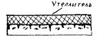
| 1. Plowing the soil to a depth of at least 35 cm with a subsequent harrowing to a depth of 10 - 15 cm. It is used in the fall to protect the soil from the freezing in the case when the digging of the kittlers is planned for the winter period. | |
| 2. Shelting the surface of the soil with insulation materials - sawdust, mats, with straw, etc. thickness of at least 10 cm. It is used in autumn to protect the soil from freezing, if the digging of the kittlers is planned for the winter period of time. |
|
| 3. Snowstanding (installation of snow-shielding shields, a device of snow shafts with a thickness of at least 80 cm). Used in winter to suspend the further freezing of the soil |
|
5. Technology for the production of earthworks
5.1. Earthwork production projects are developed by trusts of mechanization performing these works. No later than one month before the start of earthwork work, production projects should be considered and coordinated by the general contracting trust or trust of foundation-based construction. 5.2. The project for the production of earthworks should include: a) additional work performed with significant tributaries groundwater, wetlands, possible landslides and soil shifts; b) ways to dig meat and trench depth of more than 3 m or complex configuration requiring special fasteners; c) methods for preparing the grounds for embankment and production of work when erecting embankments on sedentary soils, swimming, wetlands and in groundwater tributaries; d) methods of the device of embankments on local inhomogeneous soils requiring special reassembling conditions; e) ways to strengthen slopes earth structures; (e) Calculations to substantiate the need to create possible dumps and quarries; g) Ways to move excavation masses from catlers, trenches and planning faces. In addition to these basic provisions in earthwork production projects, the following activities should be developed: a) Ways to move the soil from backup dumps for temporary storage, suitable for sweeping and swelling of the soil; b) Ways to move and carrying the missing sandy soil from other objects indicating their addresses for subfolders under the base of the floors, trenches in places of crossing them with road coatings, cables and underground communications laid within the depth of trenche. In the same section, instructions on the composition of the project production of earthworks should be given, in which they should include: a) a working drawing or an earthwork production scheme with an indication of the dimensions of the kittlers and trenches with their vertical marks based on the base (bottom) of the recess; b) calculations of the working and profile volume of earthworks of vertical planning of the territory; c) calculations of the working and profile volume of earthworks on the laying of intra-quarted underground pipelines; d) calculations of the working volume of earthworks on the laying of intra apartment underground cables; e) calculations of the working and profile volume of earthworks on the device are trough under intravadal roads, travel, platforms and tracks; (e) Calculations of the resistance of the slopes of bellows and trenches of a depth of more than 5 m in all cases or a depth of up to 5 m with adverse hydrogeological conditions. 5.3. Earthworks in places of arrangement of existing underground communications are allowed only after taking measures that exclude damage to communications, in the presence of a written permission of the Organization responsible for their operation, and in the presence of responsible representatives of construction organizations and an organization operating underground communications. Before the production of earthworks, it is necessary to designate on the area of \u200b\u200bthe axis and the boundaries of these communications with good noticeable signs. In case of detection of existing underground communications and other structures that are not marked in the existing project documentation, earthworks must be suspended, to cause representatives of organizations operating these structures at the same time to protect these places and take other necessary measures to protect against damage to the detected underground devices. Digging trenches and pita in close proximity to the existing buildings and structures, as well as existing underground communications, should be carried out only if measures are taken against the sediment of these structures and preliminary coordination of the Customer with organizations operating these buildings and structures. Events that ensure the safety of existing buildings and structures should be developed as part of a project project project. When crossing trenches with existing underground communications, the groundwork for the mechanized method is allowed at a distance not closer to 2 m from the side wall and is not closer to 1 m above the top of the cable pipe, etc. The soil remaining after the mechanized development should be refined manually without use impact tools and with the adoption of all measures that exclude the possibility of damage to these communications. 5.4. Earthwork production is allowed only after the location of the center signs. Consolidation of the breakdown is carried out with the help of remote pillars and stakes located outside the earth facilities. Pillars defining high-rise marks must have the form of references. The breakdown of earthquakes should be made using geodetic instruments with careful observance of project axes and plants. When broken down, the embankments should take into account their subsequent sediment. 5.5. When building large residential arrays (neighborhoods, microdistricts), earthworks should be carried out, taking into account the complete completion of them within certain blocks of buildings. 5.6. Earthworks on the cut and transportation of the vegetable layer of soil in blocks and on separately built-in areas should be carried out in compliance with the rules set out in 5.7 - 5.11. 5.7. The cutting of the vegetable layer of the soil should be performed only by bulldozers with a capacity of 60, 80, 100, 130 and 200 kW depending on the maximum depth of the soil cutting. With the engine power of 60 kW, the maximum cutting depth must be 15 cm, with a power of 100 kW - 20 cm, with a power of 100 and 130 kW - 30 cm, with a power of 200 kW - more than 30 cm. 5.8. Cutting with bulldozers vegetable soil can be moved to the stacks for a distance of no more than 100 m. The soil is cut into sequential longitudinal penetrations of the mechanism moving in the working position under the slope. The penetrations must be equal to the length of the boot path of the mechanism. The movement of the mechanism in the working position on the rise is allowed only with slopes not exceeding 3 - 5%. Unloading and leveling of vegetable soil in the stack begins with a remote part of the mound. The collection of vegetable soil should be performed before the onset of frosts and in winter it is not produced. The vegetable soil stacks must have entourage for transport with an angle of inclination to the horizon no more than 18 °. 5.9. To export the prepared vegetable ground from the stacking sites to its consumption is recommended by automotive vehicles, with a carrying capacity of over 3.5 tons. Immerse the plant soil in the dump trucks follows single-binded excavators with a bucket capacity of 0.25 - 0.65 cubic meters. m. 5.10. When cutting, transporting and laying in the stacks, it is forbidden to mix vegetable soil with a soil, unsuitable for plantings and crops. The quality and suitability of vegetable soil for the vocabulary works is determined by the competent soil-agronomic laboratory. 5.11. The use of vegetable soil suitable for other purposes is prohibited. 5.12. Earthworks for vertical layout of the being built-in territories should be carried out in compliance with the rules set out in sections 5.14 - 5.32 of these indications. Production of works on vertical layout of the built-in territories, as well as special sites for stadiums, squares, boulevards, etc. It is allowed only in the presence of projects for the planning of all types of underground structures and the overall soil balance. 5.13. The vertical layout of the territory of quarters or separate buildings under construction should be carried out: a) with the depth of the ground cutting of more than 0.5 m or its distance of its movement not more than 100 m - with a capacity of 60 to 200 kW or staples with a bucket capacity of 6 cubic meters. m and more; b) with the depth of the ground cutting more than 0.5 m or the distance of its movement more than 100 m (with a cutoff depth of less than 0.5 m), as well as in the presence of laid permanent or road variables on the planned territory under the foundation of roads, platforms and Roads - single-line excavators with a bucket capacity of 0.5 - 1.0 cubic meters. m with the movement of the soil by automotive themselves. 5.14. In the production of earthworks for vertical layout of the territory of Trests MosstroyMukhanization, it seems the right to choose brands and types of machines and mechanisms depending on the conditions of work, categories of soils and the presence of machines in mechanization controls. 5.15. Planning works on sites having a cut and submission are performed using bulldozers or scrapers according to the scheme specified in Fig. 1. 5.16. Vertical planning of territory using sailing excavators It is performed according to the schemes specified in Fig. 2 and 3. In fig. 2 shows the sequence of the cutting of the soil by a single-blooded excavator with a straight shovel (the capacity of the bucket of 0.5 - 1.0 cubic meters. M) with the race of the automobiles in the bottomway, and in Fig. 3 -Onekhyshov excavator with reverse shovel (bucket capacity 0.5 - 1,0 cubic meters) without an auto-free vehicle. The main parameters of single-line excavators are shown in Appendix 2. 5.17. Earthworks are made in accordance with SNIP III -4-80 "Safety Safety" and "Instructive Safety Instructions in the Development of Soils Excavators". 5.18. For the development of frozen soils when planning territories in winter conditions should use single-line excavators with reverse shovel with a bucket capacity 0.5 - 1.0 cubic meters. m. At the depth of freezing to 0.25 M, the soil is developed by excavators without pre-trainingAnd with a great depth of the freezing, mechanisms and methods for preparing frozen soil to the excavation shown in Table are recommended. 2.
Fig. 1. Motion scheme of the bulldozer when planning the territory
Fig. 2. Soil development scheme using a single-loving excavator with a straight shovel
Fig. 3. Scheme of soil development using a single-loving excavator with a reverse shovel
More detailed recommendations are given in "Guidelines for the development of frozen soil by machines and mechanisms." 5.19. In cases where the construction vehicles recommended for loosening ground soil can be applied on construction, soil should be cleaned with the help of Tan. The achieved depth of thawing by the tanks is not over 1.5 m. 5.20. In the preparation of the soil to the excavation using wedge-ham or explosion, measures must be taken, ensuring the integrity of the works near buildings, facilities, communications and safety (preventive inscriptions, the windows of neighboring buildings are protected, the danger zone is defined, etc.). 5.21. The looping of the frozen soil by the PO-126 mounted ripper on the basis of the DAT-250 tractor is carried out by parallel penetrations in layers to a depth of 0.4 m at each penetration with subsequent transverse peaks at an angle of 60 to 90 ° to the first. 5.22. Not earlier than two hours before the development of the soil, it is necessary to clear the territory intended for the planning, from snow. 5.23. For the development of frozen soil rotary excavators ETR-223B, ETR-224A are equipped with hydrophorts. 5.24. Rotary excavators ETR-223B, ETR-224A When digging a marzular soil, parallel trenches are cut, and the ridges that remain between them are developed by excavators equipped with reverse shovels with a capacity of 0.5 cubic meters. M and above. 5.25. To prevent the primer of the soil after the development of rotary excavators of the trench, they will fall asleep with the help of a bulldozer discarded soil. 5.26. The loosening of the frozen soil explosion is made in the absence of the array of buildings, structures and communications being developed. This work should be carried out by specialized areas of explosive work of mechanization controls. 5.27. Deviations of marks during vertical layout of the territory should not exceed: when cutting the soil with bulldozers ± 5 cm; when cutting soil with stages ± 10 cm; When the soil is sinking with bulldozers or strokes, taking into account the compensating layer to the ground precipitate ± 5 cm. 5.28. The stripping of the planned territory after cutting of the soil excavators should be carried out by bulldozers over the outdation of areas closed by roads and sidewalks that may be damaged by the caterpillars of bulldozers. 5.29. The dumping of the soil when planning the territory should be made by layers, the thickness of which is determined by the project for the production of earthworks and is assigned depending on the method of sealing soils. Laying of soils is carried out with horizontal or low-challenged layers. The planned surfaces of the territory should have a bias for water drain at least 0.002 or not over 0.005 in the direction of water removal. 5.30. When planning the territories to comply with the projects specified by the project and slopes, the entire bulk ground under road grounds and platforms are subject to compulsory seal. Under the landscaped areas, the soil is subject to seal with the thickness of the ilight of over 1 m. 5.31. The necessary degree of sealing of the soil is achieved by the corresponding number of passage of cargo vehicles and the observance of the thickness of the ground soil in the layer in the layer in accordance with the data of the table. 3.
Table 3.
Norms of compaction of bulk soils
|
Views of Katkov |
Number of passes at one place |
The greatest thickness of the soil layer in the layer laying, see |
| Pneumocoles weighing 10 t | ||
| Pneumocoles weighing 25 tons | ||
| Cam type D-130 weighing up to 5 tons | ||
| Cam type D-220 weighing up to 30 tons | ||
| Plumbing plate at the excavator weighing 2 t | ||
| Self-propelled pneumocalet weighing 40 t |
Fig. 4. Scheme of digging the excavators with a reverse shovel with its zigzag movement along the day surface of the platform (the number of the movement of the excavator is indicated by the numbers)
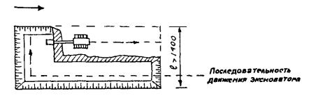
Fig. 5. Scheme of digging with an excavator with a reverse shovel with its movement parallel moves along the day surface of the site
5.38. When digging, it is necessary to simultaneously perform all earthworks provided for by the project production of earthworks, in particular, the device of ramps for entry and departure of excavators, coprov and bulldozers, a device of broadenings and recesses to accommodate coprov, water supply and other mechanisms. 5.39. Overlooked, the ground is exported to the places of the grounds under construction of the objects of the soil, provided by the vertical planning of the territory provided for in the automotive industry; b) urban landfill - with the disrepair of soil for submetocks and frustration; c) backfills of the sinuses, trenches and other objects (this or other quarter); d) reserve dumps - for temporary storage of suitable soil in the amount required for backfilling or submits during construction. Notes: 1. Leave or temporarily store the soil directly behind the upper heating of the kittlers (within the prism of collapse) or on the bottom of the finished pit is prohibited. 2. Unsuitability of soil for backfills, submetocks and mounds are established by acts with the participation of the Customer at the opening of catlogovans, trenches and planning faces. 5.40. In the soils of natural humidity in the absence of groundwater and located nearby underground structures, digging of butt and trenches with vertical walls without fasteners can be carried out at a depth (in m) not more than: 1.0 - in sand gravel soils; 1.25 - in the suede; 1.50 - in Suglinka and clays; 2.0 - in highly dense rocky soils. Notes: 1. In the presence of bulk, loose and average density of sandy and gravel soils of natural humidity, as well as at the location within the prism of the collapse of any structures or communications, the digging of buttons with vertical walls without fasteners is not allowed and is made taking into account the device required mounts or slopes. 2. It is not allowed to dig pickles and trenches with vertical walls without fasteners in the presence of converted bulk and sandy soils. 5.41. The greatest steepness of the slopes of trenches and the pitchers, suitable without fasteners in homogeneous mainland connected soils of natural humidity, should be assigned in accordance with Table 4.
Table 4.
The greatest permissible steepness of slopes of trenches and butt
|
Types of soils and their condition |
Recess depth, m |
|||||
|
corner in hail |
krutnival of slope |
corner in hail |
krutnival of slope |
corner in hail |
krutnival of slope |
|
| Bulk | ||||||
| Sand and gravel wet (unsaturated) | ||||||
| Clay: | ||||||
| Spring | ||||||
| Loam | ||||||
| Clay | ||||||
| Limsoid dry | ||||||
Table 5.
The smallest permissible distance horizontally from the sole of the removal of the removal to the nearest supports
|
Depth of recess |
Soil unsaturated |
||||
|
sandy and gravel |
supaudea |
loamy |
clayey |
lesova dry |
|
|
the distance horizontally soles of the slope to the nearest support, m |
|||||
Table 6.
Allowed groundlessness (cm) at the base when working with single-dockovy excavators
5.49. For the development of frozen soils of the kittlers in winter conditions should use single-line excavators equipped with a reverse shovel with a 10.5-cubic bucket with a tank of 0.5 - 1.5 cubic. m. 5.50. Guidelines for the preparation for the extraction of frozen soil shown in paragraphs. 5.18 - 5.26, fully applied to the development of soil in the pit. 5.51. In order to avoid soil diplots in the fallen sinuses between the slopes of the kittlers and the walls of technical subcondition, it is necessary to make a thorough seal and not allow for use for frustration of frozen soil. 5.52. Driven under the foundations of walls and underground structures should be dugout without disturbing the natural structure of the soil at the base. When performing earthworks, multi-domestic excavators and dischargers should not exceed 5 cm. Development of ground unchechats, as a rule, must be carried out by a mechanized manner. When scrolling the uncheckers for the pit mills, excavators with special enlighted buckets or other planning machines, the remaining undershoot to the design mark should not exceed 5 - 7 cm, which in the foundation places are refined manually. Random sorts of soil made during the excavation of the kittlers should be filled with homogeneous with the soil developed in the exhaust, brought to natural density. In responsible cases, the place of extinguisure is filled skinny concrete. 5.53. Earthworks on the chicken trenches for laying intra-quarterly underground communications must be carried out in compliance with the rules set out in PP. 5.54 - 5.84 of these instructions. 5.54. Drain tranches for laying in-guardian underground communications should be made by the machines recommended by Table. 7.Table 7.
|
Characteristic of soil |
Trench depth in m |
|||||
|
from 1.5 to 2.0 m |
over 2.0 M. |
|||||
|
trenches with slope |
trenches with vertical walls |
trenches with slope |
trenches with vertical walls |
trenches with slope |
||
| Lungs: | ||||||
| vegetable soil, sand, loam, without impurities, soup without impurities, slag uncomfortable | ETR-223B ETR-224A | Etz-252m | EO-3323A EO-3131 | Etz-252m | EO-3323A EO-4121A | |
| Middle: | ||||||
| Clay fatty, heavy loam, sovereok with rubble, rubble with grain size up to 10 mm | ETR-223B ETR-224A | EO-2626VZ EO-3323A EO-3131 | ETR-224A. | EO-3323A EO-3131 | Etz-252m | EO-3323a EO-4121a EO-4112 |
| Heavy: | ||||||
| pebbles and gravel, clay solid, sand with rubble more than 40%, crushed stone with grain size up to 50 mm, construction trash | ETR-223B ETR-224A | EO-3323A EO-3131 EO-4112 EO-4121A | ETR-224A. | EO-4112 EO-4121a | Etz-252m | EO-412 EO-5111 EO-4112 |
Table 8.
|
Types of soils and their condition |
Recess depth, m |
Types of fasteners |
| Soils, related (clay, loam and sandy) natural humidity | Horizontal mounting boards with transits through one board | |
| Soils Bulk (Sands) Natural Humidity | Solid vertical I. horizontal fastening | |
| Soils are different and high humidity | Also | |
| All types of soils with severe groundwater inflow |
regardless of depth |
The tongue fence below the horizon of groundwater with a beer to a depth of at least 0.75 m |
Table 9.
Prize sizes
|
Butt joint |
Seal |
Conditional Pipeline Pass, mm |
The sizes of the pit, m |
|||
| Steel | Weld | For all diameters | ||||
| Cast iron | Skinny | Rubber cuff | Up to 300 included. | |||
| Penk strand | Up to 300 included. | |||||
| St. 300. | ||||||
| Sealants | Up to 300 included. | |||||
| St. 300. | ||||||
| Asbesto-cement | Coupling like Sam | Rubber Figure Ring | Up to 300 included. | |||
| St. 300. | ||||||
| Cast iron flange clutch | Rubber ring round and type CCM | Up to 300 included. | ||||
| St. 300. | ||||||
| Any for free pipe | Any | Up to 400 included. | ||||
| Concrete and reinforced concrete | Skinny, coupling and concrete belt | Rubber Ring Round | Up to 600 included. | |||
| From 600 to 3500 | ||||||
| Plastics | All types of butt connections | For all diameters | ||||
| Ceramic | Skinny | Asphaltobitum, sealant, etc. | Also | |||
Table 10.
The smallest width of trenches with vertical walls on the bottom for laying pipelines
|
Methods of laying pipelines |
Tranche width, m, excluding fasteners at the joint connection |
||
|
skinny |
coupling, flange, folded for all pipes and flarified ceramic pipes |
||
| 1. Weaves or individual sections with the outer diameter of pipes, D, M: | |||
| up to 0.7 included. |
D +0.3, but not less than 0.7 |
||
| sv. 0,7. | |||
| 2. The same in areas developed by trench excavators under pipelines with a diameter of up to 219 mm, stacked without descent of people in the trench (narrow-handed method) | |||
| 3. The same on the plots of pipelines driven by reinforced concrete triggers or anchor devices | |||
| 4. The same on the plots of pipeline driven by non-woven synthetic materials | |||
| 5. Separate pipes with the outer diameter of the pipe d, m, including: | |||
| up to 0.5 | |||
| from 0.5 to 1.6 | |||
| from 1.6 to 3.5 | |||
Table 11.
Approximate thickness of the sandy underlying layer of a constant road under the load of H-13
After layout, the sandy base is sealing the vibrator I-7. The device of a sandy base during snowfall and for freezing soil is not allowed. 5.89. When digging is trough under intravadal roads, drives, platforms and tracks should be used single-loving excavators equipped with a reverse shovel with a bucket with a capacity of 0.25 - 0.65 cubic meters. M Bulldozers with a capacity of 80 to 200 kW, automotive lifting capacity over 3.5 tons. 5.90. In winter, a craft-milling machine ZMF-2300 and 2300a should be used for the device for the road. 5.91. When planning an earthen canvas for the road and travel of deviations from design marks should not exceed +5 cm. 5.92. Earthworks on the device of the earth canvas for crane paths should be made in compliance with PP. 5.93 - 5.103 of these instructions. 5.93. Earth canvas in the area of \u200b\u200blaying the path must be cleaned of waste of building materials, ice, snow, foreign objects and the vegetable layer of the soil. Prior to the beginning of the device, all earthworks associated with the building of the foundation of the building and the laying of underground communications should be completed in the railway zone. 5.94. The landfill of the earth can be planned in the transverse direction with a single-table profile, with a slope toward the drain from 0.008 to 0.01. The longitudinal slope of the earth cannon must be no more than 0.003. The width of the earthen canvas for the railway path built by the building should be taken depending on the type of cranes and determine by the formula:B \u003d a + 3h b + s + 2 (200 + 400) mm,
Where a is the track of the railway, mm; h b - the required thickness of the ballast under the supporting elements, mm; S - Size reference element across the rail route, mm. The initial data for determining the width of the earth canvase is given in Appendix 1 SNiP 3.08.01-85. 5.95. Earth canvas for the rail route is allowed to arrange completely from the bulk soil, as well as to organize a part of the earthen canvas on the bulk ground, and the other part is on the main ground with the development of the slope of the steepness of 1: 1.5 in the place of adjusting the bulk soil to the main; The bulk soil should be either sandy or homogeneous with the main soil. 5.96. It is prohibited for the device of the earth canvas from the bulk soil: a) apply soil with an admixture of construction waste, wood residues, rotting or swelling inclusions, ice, snow and turf; b) apply underestimating soil (clay, loam) mixed with draining, in order to avoid the appearance of water bags in the body; c) cover the soil layer with a high drainage ability to ground with a smaller drainage ability; d) lay the frozen soil, as well as a telway, mixed with frozen; e) perform work on the device of the earth canvas during intensive snowfall without the use of measures to protect the bulk soil from the inclusions of the snow; e) Seal soil with watering in winter. When renewed after the snowfall and blizzards, the surface of the suitable canvase should be cleaned of snow and ice. 5.97. The bulk of the earthen canvase should be laid with layers with a mandatory layer-by-layer seal. The thickness of the layers is determined by the machines used and equipment for the soil seal. The density (volumetric weight of the skeleton) of the ground of the earth cannol in g / m 3 should be no less: for small and dust sand - 1.7 for soupies and loams - 1.65 for heavy loams - 1.55 for dusty loam and clay - 1.5. Sandy sandy and sampling grounds of the earth cannon in the summer can be sealing with a sprayed jet of the water of each swelling soil layer. Checking the density of the ground of the earth cannon follows according to GOST 5182-78 or by any other modern methods under both rail threads. With the device of paths with wooden semispals, the density of the soil should be checked at no less than every 12.5 m, and when the device with reinforced concrete beams is under each beam. The results of the inspection must be taken into the act of passing the rail to operation. 5.98. If the required soil density is less than those specified in paragraph 5.97, it must be done. If the required soil density is not achieved in the seal process, the tracting of the earth can be performed by a special project. 5.99. The sealing of the earth can be carried out when the natural humidity of the soil is optimal. The optimal humidity of the soils are shown in Table 12.
Table 12.
To determine the natural humidity of the soil follows GOST 5180-84. If the natural moisture content of the ground cannon is optimal, before its seal, it is necessary to remove the upper mooring layer of the soil. 5.100. Filing and sealing trenches, sinuses and catlers, over which rail routes should be constructed, should be made similarly to the base of the base from the bulk soil. 5.101. In winter, it is allowed to use frozen soil for embankments and fastening the sinuses over which the cracked paths will be constructed. When laying a frozen soil, the layer-by-layer of a thickness of no more than 0.2 m with a thorough seal should be observed. The dimensions of the comic of the soil should not exceed 0.1 m. 5.102. A ballast prism is stacked on the prepared earthenware in accordance with the instructions of the SNiP manual of 3.08.01.85. 5.103. In the preparation of an earth canal under the laying of railway tracks, the following mechanisms should be applied: - excavator mounted with a bucket with a capacity of 0.25 m 3 on a pneumocole tractor of class 1.4 tons; - bulldozer on a class 3 - 10 t tractor, depending on the maximum cutting of the soil; - rollers trailed vibration weight 4 - 9 t; - car dump trucks with a carrying capacity of 3.5 - 10 tons; - Single-sided loaders on a tracked or pneumocole trip with a loading capacity of 2 - 3 tons; - Auto grader with a capacity of up to 110 hp Notes: 1. Due to the wide range of machines of various sizes, models and modifications, as well as a large range of replaceable attachment equipment to these machines, in the nomenclature of earthmoving equipment included mainly models of machines produced domestic industry During 1990 - 1996 These models will be in operation for several years (applications 3 - 11). 2. On the execution of earthworks, foreign earthmoving machines can be used, which in their technological parameters correspond to the scope of work and the conditions of their execution. The nomenclature of foreign cars and their parameters can be obtained from separate reference directory. Create such information within the framework of this work is not possible due to its limited volume. 3. Did not reflect within the framework of these indications of special work (punctures under the roads, explosive work, wall in the ground, fixing the soil, etc.), since these types of work require special justifications in the project documentation for their implementation.Attachment 1
Appendix 2.
The main parameters of single-loving excavators
A) - equipped with direct shovel; b) - equipped with a reverse shovel; c) - equipped with draglin; R is the greatest radius of digging in m; R 1 is the largest unloading radius in M; H 1 - the highest height of digging in m; H 2 - a lot of unloading height in m; H 3 - the greatest depth of digging in m; N 4 - the greatest height of unloading in m; L - the length of the main boom in m; R 2 - the largest unloading radius in m; H 5 - the height of the unloading in m; H 6 - digging depth with lateral passage in m; H 7 - digging depth with end pass in m.
Appendix 3.
Specifications Trench chain excavators
|
The name of indicators |
||||
| Base |
MTZ-82 with bulldozer dump |
MTZ-82 with bulldozer dump |
TT-4 tractor |
T-170m P00 Tractor |
| Engine power, kW | ||||
| Mass, T. |
19.5, with add. Equipment 20.6 |
|||
| Trench sizes, m: | ||||
| depth | ||||
| width |
2.8 at the top 0.8 - 1.0 at the bottom |
|||
| Working speed, m / h | ||||
| Transport speed, km / h | ||||
| The width of the bulldozer dump, mm | ||||
| Dump height, mm | ||||
| Dump Blow, m | ||||
| The angle of rotation of the dump, hail. | ||||
| Optional equipment | Milling cutter for asphalt, bare worker, set of chains for trench passages | Barbell Equipment for cutting cracks in a marzlot, asphalt depth to 1.4 m | With complement Equipment, Trench Depth 3.5 m | Bare worker, set of chains for trench passages |
Appendix 4.
Technical characteristics of trench rotary excavators
|
The name of indicators |
||
| Base | Tractor T-170 tractor assemblies | |
| Engine power, kW | ||
| Mass, T. | ||
| Trench sizes, m: | ||
| depth | ||
| Width without slopes | ||
| with slopes at the top | ||
| Working speed, m / h | ||
| Transport speed, km / h | ||
| Rotor: | ||
| Diameter, mm. | ||
| Number of buckets | ||
| Bucket capacity, l | ||
| Cutting speed, m / s | ||
| Conveyor ribbon width, mm | ||
| Tape speed, m / s |
Appendix 5.
Technical characteristics of single-line universal excavators with a bucket with a capacity of up to 0.2 m 3
|
The name of indicators |
Borkeks-1621 |
BOREKS-1623. |
||
| Base |
T-25 tractor |
T-30 tractor |
Backhoe loader |
|
| Purpose | For earthworks in soils I - III Cat. | For earthworks in soils I - Vat. and loading and unloading works in cramped conditions | For earthworks in soils I - IV Cat. and loading and unloading | |
| Capacity bucket, m 3 | ||||
| Engine power, kW | ||||
| Mass, T. | ||||
| The greatest depth of digging inverse shovel, m | ||||
| The angle of rotation of the working equipment in the plan, hail. | ||||
| The greatest effort of digging, kN | ||||
| Shift axis digging, m | ||||
| Speed \u200b\u200bof movement, km / h | ||||
| Optional equipment |
pogot. bucket 0.25 m 3 |
pogot. bucket 0.25 m 3 |
pogot. bucket 0.86 m 3 |
Appendix 6.
Technical characteristics of incomplete hydraulic excavators with a bucket with a capacity of 0.25 m 3 for earthworks in soils of I- IV categories, as well as loading and unloading works
|
The name of indicators |
BOREKS-2628. |
|||
| Base | ||||
| Capacity bucket, m 3 | ||||
| Engine power, kW | ||||
| Mass, T. | ||||
| Pressure in the hydraulic system, MPa | ||||
| The greatest height of the unloading, m | ||||
| Speed \u200b\u200bof movement, km / h | ||||
| Optional equipment | Direct and reverse shovel, grab, forks, hydraulic hammer, bulldozer, tooth-ripper, grip, replaceable buckets, telescopic handle | Pelo. bucket 0.83 m 3, reverse and straight shovels, grab, hydraulic hammer, grip, tooth-ripper, replaceable buckets | Pelo. bucket 0.5 m 3, reverse and straight shovels, grab, hydraulic hammer, grip, tooth-ripper, replaceable buckets | Pelo, bucket 0.5 m 3, reverse shovel, grab, hook suspension, grip, hydraulic hammer, replaceable buckets |
Appendix 7.
Specifications of hydraulic single-loving excavators for the development of non-member soils of the I- IV categories and pre-loosened frozen and rock soils with inclusions of no more than 200 mm, as well as for loading and unloading
|
The name of indicators |
||||
| Base | Tractor Tractor Tractor | Pneumatic sober | Crawler | KAMAZ-5531 chassis |
| Capacity bucket, m 3 | ||||
| Engine power, kW | ||||
| Mass, T. | ||||
| Pressure in the hydraulic system, MPa | ||||
| The greatest depth of digging, m | ||||
| The greatest height of the unloading, m | ||||
| The greatest radius of digging, m | ||||
| Speed \u200b\u200bof movement, km / h | ||||
| Replaceable work equipment | Reverse shovel with buckets, m 3: 0.25; 0.4; 0.5; 0.63; 0.8; Pogwood, bucket 1.4 m 3, direct shovel, grab, tooth-ripper, hydraulic hammer | Reverse shovel with buckets, m 3: 0.25; 0.4; 0.5; 0.63; 0.8; Pelo. Bucket 1.4 m 3, straight shovel, grab, tooth-ripper, hydraulic hammer | Excitement. buckets 0.15; 0.25; 0.5; 0.63 m 3, planning and profile buckets 0.5 m 3, planning dump 2 m wide, ripper, complement. Box 1.2 M. | Telescope. Arrow 3.2 m, buckets 0.25; 0.5; 0.63 m 3, profile 0.63 m 3, Planning 0.5 m 3, Extension, Single-toke Ripper, Dump |
Appendix 8.
Specifications of single-loving excavators for earthworks in soils of I- IV categories and pre-loosen rock and frozen soils with inclusions of no more than 400 mm, as well as for loading and unloading
|
The name of indicators |
||||
| Base |
Crawler |
Pneumatic sober |
Crawler |
|
| Drive of work equipment |
Cable |
Hydraulic |
Hydraulic |
Cable |
| Capacity bucket, m 3 | ||||
| Engine power, kW | ||||
| Mass, T. | ||||
| Pressure in the MPA hydraulic system | ||||
| The greatest radius of digging, m | ||||
| The greatest depth of digging, m | ||||
| The greatest height of digging, m | ||||
| The greatest height of the unloading, m | ||||
| The greatest unloading radius, m | ||||
| Speed \u200b\u200bof movement, km / h | ||||
| Replaceable equipment | Direct and reverse shovels, dragon, grab, faucet, puffy equipment | Reverse shovel, grab, hydraulic hammer, tooth-ripper, buckets of various purposes | Direct and reverse shovels, grab, hydraulic hammer, ripper, drill equipment, hook suspension | Direct and reverse shovels, dragine, grab, crane |
Appendix 9.
Types of single-line excavators used for the development of kittlers
|
Xractering of soils |
Cutlery depth up to 2 m |
The depth of the pit is up to 4 m |
The depth of the pit is up to 6 m |
Water saturated soils with a depth of pit |
||||
|
with the volume of the removed soil up to 1.5 thousand cubic meters. M. |
with the volume of the exhausted soil over 1.5 thousand cubic meters. M. |
with the volume of the removed soil up to 4 thousand cubic meters. M. |
with the volume of the exhausted soil over 4 thousand cubic meters. M. |
with the volume of the removed soil up to 6 thousand cubic meters. M. |
with the volume of the removed soil over 6 thousand cubic meters. M. |
|||
| Easy vegetable, sand and sovereok without impurities, slag uncomfortable | EO-2226 EO-3323A | EO-3323A EO-3131 | EO-3323A EO-3131 | EO-3123 EO-4112 EO-412A | EO-4112 EO-4121a | EO-5111 EO-5222 | EO-4112 Dragon | EO-4112 Dragon |
| Middle clay fatty, heavy loam, sovereok with rubble, rubble grain size up to 40 mm | EO-3131 EO-3323A | EO-3223A EO-3131 | EO-4121A EO-4112 | EO-4121A EO-4112 | EO-4121A EO-4112 | EO-5111 EO-5222 | EO-4112 Dragon | EO-4112 Dragon |
| Heavy pebbles and gravel, clay solid, sand with rubble more than 40%, construction trash, crushed stone with grain size up to 50 mm | EO-4121A EO-4112 | EO-5111 EO-5122 | EO-5111 EO-5122 | EO-5111 EO-5122 | EO-5111 EO-5122 | EO-5111 EO-5122 | EO-5111 Dragon | EO-5111 Dragon |
Appendix 10.
Technical characteristics of bulldozers
|
The name of indicators |
|||||
| Base | DT-75P-P2 DT-75DD-C2 | DZ-190. | T-170.01 | DET-250M2. | T-500 |
| power, kWt | |||||
| Mass, kg. | |||||
| Dump |
. |
. |
|||
| Overall dimensions, mm: | |||||
| length | |||||
| height | |||||
| Cutting angle, hail. | |||||
| Lifting, mm. | |||||
| Lowering, mm. | |||||
| Motion speed, km / h |
Appendix 11.
Technical characteristics of loose equipment hanging on tracked tractors
|
The name of indicators |
|||||
| Types of tractors | Dt-75D-PC2 DT-75N-PC2 | T-170.00 T-170.01 T-170M.00 T-170M.01 | DET-250M2 DET-250M3 | T-330 | T-500 |
| Tractors tractors | |||||
| Number of teeth | |||||
| Blowing, mm. | |||||
| Capture width, mm | |||||
| Mass, kg. |
Appendix 12.
Technical characteristics of the earth-milling machine ZMF-2300
| 1. General Provisions. 1 2. The composition of earthworks. 2 3. Organization's duties in the production of earthworks. 2 4. Sequence of excavation of earthworks. 3 5. Technology for the production of earthworks. 4 Appendix 1 The act of transferring the site for the production of the work of the zero cycle. 19 Appendix 2 The main parameters of single-line excavators. 19 Appendix 3 Technical characteristics of trench chain excavators. 20 Appendix 4 Technical characteristics of trench rotary excavators. 20 Appendix 5 Technical characteristics of single-line universal excavators with a bucket capacity up to 0.2 m 3 21 Appendix 6 Technical characteristics of incomplete hydraulic excavators with a bucket with a capacity of 0.25 m 3 for earthworks in the soils of IV categories, as well as loading and unloading work. 21 Appendix 7 Technical characteristics of hydraulic single-loving excavators for the development of non-member soils of categories and previously loose frozen and rock soils with inclusions of no more than 200 mm, as well as for loading and unloading. 22 Appendix 8 Technical characteristics of single-loving excavators for earthworks in soils of I- IV categories and pre-loosened rock and frozen soils with inclusions of no more than 400 mm, as well as for loading and unloading. 22 Appendix 9 Types of single-line excavators used to develop kittlers. 24 Appendix 10 Technical characteristics of bulldozers. 25 Appendix 11 Technical characteristics of loose equipment hanging on tracked tractors .. 25 Annex 12 Technical characteristics of the ZMF-2300 agricultural machine. 25. |
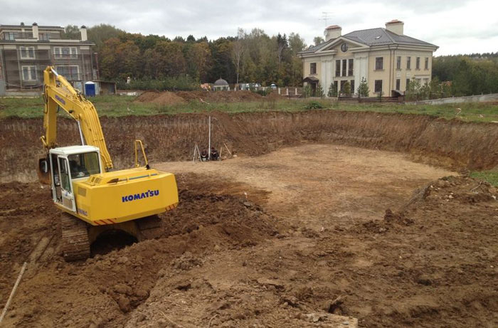
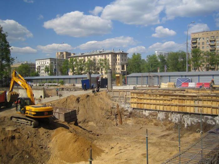
Creating a pit is the basis of any construction. It is from him that all work on the construction site begins. Its creation is based on an existing project.
Spetsdontazh is ready to offer its customers for the development of catlers of any size and volume, while the initial cost of work is from 300 rubles per cubic meter, including the process of exploring the seizure of the soil to the polygons. The final cost of performance is formed by the chosen methodology for conducting work and other factors that are individual.
Our company has a significant experience in conducting such work, uses modern techniques and technologies, which makes it possible to increase overall efficiency, reduce work time and their cost. We are guaranteed to provide daily recycling up to 1.5 cubic meters of land, including its cleaning from the construction site.
Among the factors that have a direct impact on the final value of the provision of services for the development of a kittle man include:
- The nature of the area on which works are planned.
- Features of the future foundation and depth of it.
- Type of soil and its humidity. The presence or absence of groundwater.
- Terms of work and planned volumes.
- Seismological situation at the facility.
- The main hydrotechnical parameters of the works and features of the geology of the soil.
- Types used for construction techniques.
- Distance to utilization polygons.
The formation of value is performed in each case individually, while in the cottage construction The average cost of work is varied within 300-400 rubles per each cubomener of the soil removed.
Despite the seeming simplicity, the process of developing pitfalls under the foundation is not only labor-intensive, but also technically difficult work, the execution of which is better to trust professionally trained people. Competent layout of the work allows not only to speed up the construction time of the object, but also adjust the consumable estimate towards the decrease.
We are ready to offer customers a full range of services related to the arrangement of Kotlovanov. We do:
- Planning on terrain
- Mechanized development of pit or trench
- Loading in cargo transport for the export of soil from the construction site
- Direct fit of the dump
SpetsDontaza company uses exclusively mechanized ways to carry out work, and compact mini-excavators with high performance are used for small volumes. Used brand techniques JCB, Hitachi, Liebherr and others are among the best on the market. It is equipped with the all necessary set of hinged equipment, which allows working with the depth of the pita to 19.5 meters inclusive.
Together with the sampling of the soil, we organize on their own and its export. This allows you to simplify and speed up the work process, reduce costs and reduce the possibility of inconsistencies in the simultaneous work of several companies. In the process of export, we use a three-shift scheme of work, which allows you to daily dispose of up to 3 thousand cubic meters of soil everybody.
Stages of construction Kotlovanov
Our specialists have sufficient practical experience in creating construction kittlers, which allows them to split work into several consecutive stages:
- At the first stage, geodesic exploration of the area is carried out, the composition and quality of the soil is determined, the presence of soil waters. Compilation of the drawings of the future pitted.
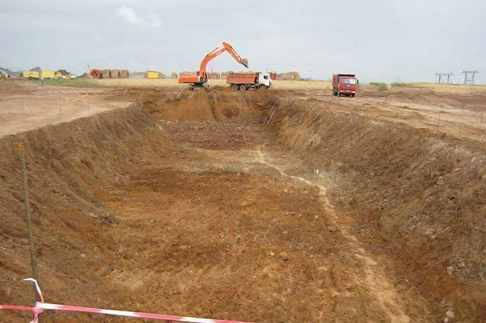
- Works are carried out on the excavation of the soil in accordance with the previously composed plan.
- The soil loading is carried out on motor vehicles with its subsequent export from the territory.
- A separate item is to control the quality of the work performed at all stages.
In the process of operation of the building, all structural loads are perceived by a pit, so at the stage of its arrangement it is necessary to comply with the conditions prescribed in the plan.
The following factors have direct influence on the creation of a pitcher:
- Properties of soil. In this case, there are in mind its strength characteristics. For Moscow and the region the greatest distribution Received loogline soil or soil with high levels Peat content.
- The size of the future object. The future dimensions of the structure under construction form loads that will affect the pit, which requires in advance to provide the ability to hold them.
- Base the foundation. This factor is largely repelled from the height of the groundwater and the degree of primerization of the soil in winter conditions. Considered in the process of design and load on the foundation, taking into account the type of soil. For example, the level of shutback for sandy and clay soil is 0.5 and 0.7 meters, respectively.
- Climatic conditions at the time of work. In cases where work is performed in winter, and the soil freezes from 0.25 meters and more, pre-thawing is required. Under the conditions of autumn or spring, the abolition of work is complicated by the state of access roads and dirt roads in the grounds of soil utilization, blur directly at the construction site.
- Volume and composition preparatory work. This group includes clearing the terrain, the transfer of communications, a decrease in the height of groundwater location and so on.
We carry out the development of a pit and carry out any work of the preliminary construction phase in Moscow and in other regions of Russia.
Kotlovan - specially dumped pit for bookmarking the foundation or for the device underground facilities. Its configuration, depth and other parameters depend on the following factors:
- type, dimensions, a lot of future buildings;
- type of foundation - tape, pile, etc.;
- soil type;
- underground water level;
- freezing level;
- seismic situation in the area of \u200b\u200bdevelopment;
- availability / absence near other structures and communications.
You can order work on the development of a pit in our company
Prices for the operation of the zero cycle and the transfer of technology is the lowest in the region. For all questions, call: 8 800 707-72-09
Technological card for the development of a pit
With the beginning of the development of the pit in our company, a number of events are held, which reduce the possible risks of building construction structures:
- geological / hydrogeological studies;
- watership activities (on fine-grained soils with high groundwater occurrence);
Preliminary research
Before proceeding with the design of the structure, our specialists are mandatory to figure out the conditions in which it will be erected and functioning. The first thing that is performed at the preparation phase is geological research of the site.
We adhere to the following work plan:
- Study of archival documents on the area. Data on tectonics, layers of soil, seismic setting. All engineering and geological information that is in stock.
- Field stage. Acquaintance with the site in place: study of the relief, geophysical methods, penetration of mine workings / drilling of exploration wells. Fence of soil samples. At this stage, the sequence and thickness of the layers is specified, as well as the level of groundwater location.
- Cameral stage. Laboratory means are studied soil samples (composition, physico-chemical characteristics) and water samples (chemical composition).
If construction is planned in the waterfront territory or in coastal zoneAlso carry out hydrogeological studies.
We have our own experts on geological exploration and hydrogeologists, in the presence of all necessary equipment for field work (drilling rigs, etc.) and equipment for laboratory research.
The main stages of the development of the pit
The development of the pit under the foundation is carried out in the following order:
- Geodesic breakdown: the parameters and the angles of the kittle are measured. Marking is carried out with the help of levels and theodolites. Trenches are performed around the perimeter of the future pit. A picking from the columns and boards is made, the cords are stretched between the columns. Fitting indicates the boundaries of the pit and the future facilities.
- Shuttle work. First, the turf is removed (vegetable layer of the soil), then digging the kittle on the design depth. The steepness of the slopes is calculated in the project and depends on the peculiarities of the soil.
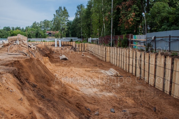
- Treatment of slopes. The goal is to protect the walls from shuffling, and the pit itself - from the penetration of groundwater.
We strengthen the slopes with metal sheets.
Other options are bituminization, freezing - more energy-intensive and less effective.
- The entire amount of soil when developing a pit is divided into parts. The majority is exported outside the site, the part remains for filling the sinuses of the kittlement at the end of the fill of the foundation.
We are developing a catlery for GOST and the construction rules (45.13330.2012 SP, last revision of 3.02.01-87 SNiP), and also make out all the necessary accompanying documentation.
Methods for developing a pit and necessary equipment
There are 4 methods of developing a mechanized manner:
- mechanical - ground removal using excavators;
- hydromechanical - flushing with powerful water jets. It is used in building near water sources. In the first stage, the soil is blurred, then the water-grained mass is moved to the dump and separated water;
- explosive through explosions - dynamite, trotyl, etc. is used on rock, eternal and other solid soils;
- combined - a combination of a mechanical and explosive method.
Selecting the machine when using the mechanical method depends on the scope:
- for the development of soil in pita, trenches are a single cyclic excavator;
- when laying engineering networks - multiflower, rotary, continuous action;
- under the device of iron and highways - the grader-elevator.
Single excavator can be equipped with:
- straight shovel. Used in the development of the soil above the layout of the machine;
- reverse shovel, dragine - below level;
- grader. It is used in both cases on a bulk and loose soil.
Regardless of the working body, the soil can be seized:
- in dump within the reach of the excavator;
- with simultaneous loading in T / C - the vehicle with a lifting capacity from 3.5 to 10 tons.
The place of work of the excavator is called a caution. Reception that is obtained when working - penetration. The frontal bearing - when its axis coincides with the direction of development, otherwise - the side.
The price per M3 of the development of the pit depends on the volume of earthworks used by the technique, the working conditions. Together with you we will pick up the most profitable option for you.
Features of the development of a pit close to an existing building
The development of kittlers near houses is the process of increased complexity and responsibility. In addition, it is necessary to work in cramped conditions, there is a risk of damage to the previously erected buildings. As a result of an ill-conceived organization of work:
- in the foundations and walls of neighboring houses, cracks may appear;
- the windows of doorways, staircase marches are formed;
- shear slabs of overlaps.
Those. Disruption of normal operation appear, in extreme cases there may be an emergency. First of all, the construction in the neighborhood suffers at home on weak soils.
Technologists call the causes of deformations of buildings during the device about them of new foundations:
- crashing the base of the base towards the area zone (i.e. towards the pit);
- soil shift from under the foundation due to open water reservoirs;
- dynamic load on the soil when immersing piles shock (sometimes vibration) method;
- development of frozen soils and freezing of waist.
All these risks impose on the production of earthworks and the development of a certain restrictions:
- it is impossible to use an explosive method of ground excavation;
- it is impossible to use the immersion of the discourse;
- construction works In the pit, related to the use of heavy equipment should be reduced to the maximum.
In cases where construction work is carried out close to neighboring houses and the soles of foundations are on one mark, construction is carried out by the invigorators. Each next capture is done at the end of the foundation on the previous segment.
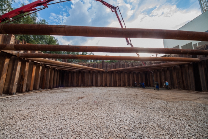
When developing deep pita, when the outcower of the foundation of the new house is located below than the old, the installation of a tongue fence is obligatory or the wall in the soil. It should also be carefully carried out by water supply, since it can provoke an additional soil drawdown.
Another risk in developing may occur in the presence of underground communications. For the period of earthworks, they should be lifted and suspended in the excavation. Pipelines are placed in protective steel housings. If the communications were found directly during the operation, the soil removal continues manually. Be sure to inform the organization that is responsible for these communications.
We will perform the development of the pit and the removal of the soil quickly, efficiently and absolutely safe for the existing development.
Developing a pit in Moscow? Contact us!
We carry out the work of the preliminary cycle throughout Russia, we provide services for any construction:
- pit for foundations and underground facilities;
- trenches for communications;
- development of pitchers for LPP support;
- device and strengthening of punching fences of any destination - for building kittlers, hydraulic objects, road works, collectors, etc.;
- preliminary research;
- pile tests;
- design;
- water supply;
- leader drilling;
- organization of the construction site.
- democratic price of the development of pit and other services;
- qualified specialists;
- in stock All necessary technique;
- a large assortment of tongs;
- certificate SRO;
- quick deadlines;
- quality assurance.
Leave an application for a consultation of a technical specialist
Find out how much you can save with us
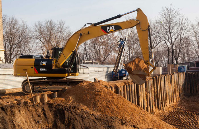
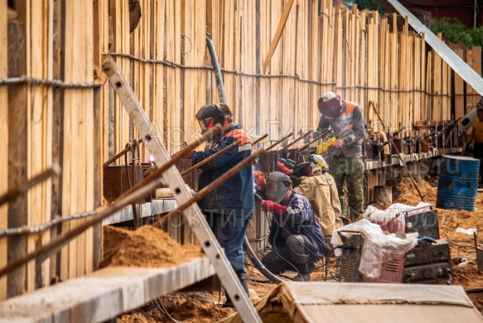
A rather complicated technological process, including digging kittlers and the strengthening of slopes, characterized by phased implementation, is called the development of kittlers. Today, these works are fully mechanized: excavators, bulldozers and other special equipment are used, piles are immersed to build a tongue fencing, the fence itself is performed, etc.
List of works included in the concept: Developing a pit
The modern development of catlovanov provides for the preceding performance of some operations. It:
- geological and reconnaissance surveys, on the basis of which determines the degree of density and composition of the soil, as well as the presence of groundwater and the level of their occurrence; This information is necessary to calculate loads and select the pile immersion method;
- project development;
- coordination of documentation.
- digging care;
- provision of waterproofing foundation (drainage);
- digging trenches;
- arrangement of embankment and slopes with tongue fences;
- distribution and removal of removed soil;
- laying communication networks;
- reverse fusion;
- vertical planning of the construction site;
- drilling and drilling of reinforced concrete piles or other immersion method;
- construction of the foundation.
Earth structures created in the process of developing pita can be temporary and permanent. Temporary belongs:
- pitted under the foundation;
- trenches for laying communications;
- drive under the outdoor ground - cavalier.
The development of catlovanov can be done at any time of the year, but in the cold it is required to attract additional specialized equipment for loosening the frozen soil, harvesting snow, etc.
The selection of technicians depends on climatic and local conditions, as well as from the state of the soil. In cases where it is impossible to use classical earthmoving equipment, manual work, supplemented by means of small mechanization, can be used for garbage.
The developed project should contain all the runways of underground and ground communications. There is also a list of activities aimed at preserving nearby buildings and structures.
The outlined ground must be stored in such a way that it does not cause sinking of slopes and the walls of the pit. The tongue attachments are set in such a way that they do not interfere with further work. In the case when the depth of the recovery exceeded the design mark, the revealed ground is stacked, which will be trambered in layers.
Drilling, well device and pile drivingAlso, the construction of the foundation is carried out immediately after the completion of the work on the device of the pit. If there is an unplanned break between these stages, measures are being carried out to protect the pit from natural factors. For example, needle filter installations or other equipment are installed to remove precipitation.
The scope of work on the device is 5-15% of the total construction of a specific object. At the same time, their cost, including the pile bob, can be up to 20%.
A competently designed construction site under the foundation of a building or structure guarantees the planned object operational safety, reliability and durability. Similar task on shoulder only with highly qualified specialists who have an impressive experience of such work, which have all the necessary equipment and modern equipment. And all this is ready to provide your facility to the company Sotran, a construction and transport enterprise, whose account has dozens of delivered, successfully functioning objects today.


