The hydraulic system contains a tank connected to the pump, pressure and discharge lines and a valve block with electromagnetic control. One of the block distributors is equipped with a hydraulically operated shut-off device with two cavities, a plunger and one shut-off valve. The hydraulic system has executive hydraulic motors of various energy capacities. A device of two pressure levels is connected in series to the pressure line of the pump, the drain cavity of which is connected to the tank through the drain line. The safety valve of the device with a lower setting pressure in the working position of the distributors is connected with the cavity of the hydraulically controlled shut-off device without a shut-off valve or with a hydraulic motor of lower power consumption. The use of a device of two pressure levels in the hydraulic system of the combine allows to reduce pressure overshoots and energy consumption and to increase the efficiency of its operation. 1 ill.
The invention relates to agricultural engineering, in particular to the hydraulic system of a combine harvester.
Known hydraulic system of a combine harvester (Self-propelled combine harvester "Yenisei-1200". Technical description and operating instructions. Krasnoyarsk, 1988, S. 75-78), containing a pump, a safety valve, manually operated distributors, the working sections of which are equipped with hydraulically controlled locking devices with cavities, a plunger and shut-off valves, hydraulic actuators of various energy capacities.
The disadvantage of the known device is that it uses mechanically controlled distributors, and the setting pressure of the safety valve is insufficient for the operation of the energy-intensive hydraulic drives of the combine mechanisms: lifting the header, when using wide-cut headers; scrolling the drum, when clogging it with a grain mass. At the same time, throttles are used in the hydraulic system for the operation of low-energy hydraulic drives, to reduce the speed of the actuating hydraulic cylinders, and for the operation of hydraulically controlled locking devices, for example, when lowering the header, the maximum setting pressure of the safety valve is used. All this leads to a decrease in the efficiency of the hydraulic system and a complication of its design.
Also known is the hydraulic system of a combine harvester (Self-propelled combine harvesters "Don-1500", "Don-1200". Technical description and operating instructions. Rostov-on-Don, 1986, p. 137-156, Fig. 117), taken as prototype, including a pump, a safety valve, a distributor, the working sections of which are equipped with hydraulically operated shut-off devices with cavities, a plunger and shut-off valves, hydraulic actuators of various energy capacities. The setting of the safety valve of the device is sufficient for the operation of the energy-intensive hydraulic drive of the mechanism for lifting the header of the combine in the working position "raising the header" when using different headers. However, in the working position of the hydraulic drive "lowering the header" when other hydraulic drives with plunger-type actuating cylinders operate, the working pressure of the hydraulic system, equal to the setting pressure of the safety valve, is used only to open the shut-off valve of the hydraulic system of the shut-off device, which is a disadvantage of the device. In addition, for the operation of a hydraulic drive of low energy consumption, to reduce the speed of the hydraulic actuators, throttles are used in the hydraulic system, which further reduces its efficiency.
The technical result of the invention is expressed in increasing the reliability of the hydraulic system and its efficiency. This is achieved by the fact that the hydraulic system of the combine harvester includes pressure and drain lines, a tank, a pump, a valve block with electromagnetic control, one of the valves of which is equipped with a hydraulically controlled shut-off device with cavities, a plunger and one shut-off valve, hydraulic actuating motors of various energy capacities. the pressure line of the pump is connected in series with a device of two pressure levels, the drain cavity of which is connected to the tank through the drain line, and the safety valve with a lower setting pressure in the working position of the distributors is connected to the cavity of a hydraulically controlled shut-off device without a shut-off valve or with a hydraulic motor of lower energy capacity. Comparative analysis with the prototype shows that the claimed invention differs from the prototype in that a device of two pressure levels is connected in series to the pressure line of the pump, the drain cavity of which is connected to the tank through the drain line, while the safety valve with a lower setting pressure in the working position of the distributors is connected to a cavity of a hydraulically controlled shut-off device without a shut-off valve or with a hydraulic motor of lower power consumption. Verification of compliance of the claimed invention with the requirement of inventive step showed that the invention does not follow explicitly for a specialist from the prior art, since from the latter, the influence of the transformations prescribed by the invention, characterized by essential features distinguishing from the prototype, on the achievement of the technical result was not revealed.
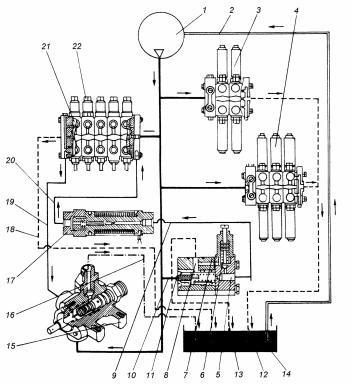
The drawing shows a schematic diagram of the hydraulic system of a combine harvester.
The hydraulic system of the combine harvester includes pump 1, a device of two pressure levels 3 is connected in series to the pressure hydraulic line 2 of pump 1, which has an overflow valve 4 connected to the tank 5 through a drain cavity 6 and a drain line 7. A three-position four-line valve is connected in series to the control line 8 of the overflow valve 4 solenoid valve 9 and in parallel a safety valve 10, set to high pressure. The solenoid valve 9 in the neutral position through the drain cavity 6 and the hydraulic line 7 connects the control line 8 with the hydraulic tank 5 and disconnects it from the second safety valve 11, which is set to a lower pressure. The fourth line of the solenoid valve 9 is plugged. Safety valves 10, 11 through the drain cavity 6 and the hydraulic line 7 are connected to the tank 5. In parallel, two electromagnetic three-position four-line distributors 13, 14 are connected to the pressure hydraulic line 2 from the pump 1 through the hydraulic line 12 (the rest are conventionally not shown), combined into block 15. Distributor 13 is equipped with a hydraulically controlled locking device 16, which has two cavities 17, 18, a plunger 19 and one shut-off valve 20, through which the distributor is also connected to the hydraulic line 21 with hydraulic plunger cylinders 22, 23, for example, the hydraulic cylinders of the header lifting and lowering mechanism, the most energy-intensive in the hydraulic system of a combine harvester ... The distributor 14 is connected through hydraulic lines 24, 25 to a double-acting hydraulic cylinder 26, for example, a hydraulic cylinder of the drum reverse scrolling mechanism, which has a working stroke when the rod is extended during the reverse rotation of the drum and idle when the rod is returned to its original position. At the same time, the working stroke of the mechanism is also the most energy-consuming, and the idle stroke of the mechanism, on the contrary, is the least energy-consuming in the hydraulic system of a combine harvester. The cavities 17, 18 of the hydraulically controlled shut-off device 16 through the drain cavity 27 of the unit 15 and the hydraulic lines 28, 7, connected to the tank 5. The control panel of the electromagnetic distributors 9, 13, 14 (conventionally not shown).
The device works as follows.
After switching on the pump 1, the working fluid with a relatively low flow rate enters the hydraulic tank 5 through the hydraulic control line through the electromagnetic distributor 9, the drain cavity 6 and the hydraulic line 7. The overflow valve 4 opens and the main part of the pump 1 working fluid supply is drained into the hydraulic tank 5 through the drain cavity 6 and hydraulic line 7. At this point, the main system is idling. When an electrical signal is supplied from the control panel, simultaneously to the electromagnetic distributors 9 and 13, their spools are removed from the neutral position, while the distributor valve 13 is brought out, for example, to the working position "lifting the header". The electromagnetic distributor 9 disconnects the control line 8 of the overflow valve 4 from the hydraulic tank 5, and the electromagnetic distributor 13 connects the pressure hydraulic line 2 through the hydraulic line 12 with the cavity 18 of the hydraulically controlled shut-off device 16. The overflow valve 4 closes and the entire flow of working fluid from the pump 1 enters the cavity 18, and at the same time, moving the plunger 19, it is directed through the shut-off valve 20, the hydraulic line 21 to the hydraulic cylinders 22, 23 (the most energy-consuming hydraulic motors of the hydraulic system of the combine harvester) and brings their plungers out of their original position, lifting the header. The pump 1 flow is fully used on useful work hydraulic motor (header lifting), hydraulic cylinders 22, 23, because the latter have the largest capacity in the hydraulic system of a combine harvester. After the full exit of the rods of the hydraulic cylinders 22, 23, the safety valve 10 is triggered, adjusted to a higher pressure, after the electrical system is turned off, the spools of the electromagnetic distributors 9 and 13 return to their original position and the main system starts to work in idle mode.
When an electrical signal is supplied from the control panel to the solenoid valves 9 and 13 at the same time, their spools are removed from the neutral position, while the spool of the distributor 13 is brought to the working position "lowering the header", and the solenoid valve 9 connects the control line 8 of the overflow valve 4 with the safety valve 11 The overflow valve 4 closes and the entire flow of the working fluid from the pump 1 through the pressure hydraulic line 2 through the hydraulic line 12 enters the distributor 13 into the cavity 17 of its hydraulically controlled shut-off device 16 and moves the plunger 19, which opens the shut-off valve 20, connecting the hydraulic cylinders 22, 23 with the hydraulic tank 5 through the drain cavity 27 of the distributor block 15 and hydraulic lines 28, 7, lowers the header. At this moment, the cavity 17 of the hydraulically controlled shut-off device 16 is simultaneously connected to the safety valves 10, 11, and when the plunger 19 is fully displaced, the safety valve 11, set to a lower pressure, is triggered. After turning off the electrical system, the spools of the electromagnetic valves 9 and 13 return to their original position and the main system starts to work in idle mode.
In case of clogging of the thresher drum of a combine harvester with a grain mass, the thresher is turned off and the drum reverse scrolling mechanism is connected to the drum shaft (conventionally not shown).
The electrical signal from the control panel is simultaneously supplied to the electromagnetic distributors 9 and 14, their spools are removed from the neutral position, while the valve of the distributor 14 is brought out, for example, to the operating position "drum roll". The solenoid valve disconnects the control line 8 of the overflow valve 4 from the hydraulic tank 5. The overflow valve 4 closes and the entire flow of the working fluid from the pump 1 through the pressure hydraulic line 2 through the hydraulic line 12 goes to the electromagnetic distributor 14 and through the hydraulic line 25 is directed to the plunger cavity of the hydraulic cylinder 26, carrying out the working the stroke of the drum reverse scrolling mechanism. At this moment, the plunger cavity of the hydraulic cylinder 26 is connected to the pump 1 and to the safety valve 10, adjusted to a higher pressure, and the rod cavity of the hydraulic cylinder 26 through the hydraulic line 24, the distributor 14, the drain cavity 27 of the distributor block 15 and the hydraulic lines 28 and 7 is connected to the hydraulic tank 5. After the full exit of the rod of the hydraulic cylinder 26, the electrical system is briefly turned off and the main system begins to work in idle mode. Then the electrical signal is simultaneously again supplied to the electromagnetic distributors 9 and 14, their spools are removed from the neutral position, while the valve of the distributor 14 is brought out to another operating position "idle drum rotation". The solenoid valve 9 connects the control line 8 of the overflow valve 4 with the safety valve 11. The overflow valve 4 closes and the entire flow of the working fluid from the pump 1 through the pressure hydraulic line 2 through the hydraulic line 12 goes to the distributor 14 and through the hydraulic line 24 is directed to the rod cavity of the hydraulic cylinder 26, carrying out idling of the drum reverse scrolling mechanism. At this moment, the rod cavity of the hydraulic cylinder 26 is connected to the pump 1 and simultaneously with the safety valves 10 and 11, and the plunger cavity of the hydraulic cylinder 26 through the hydraulic line 25, the distributor 14, the drain cavity 27 of the distributor block 15 and the hydraulic lines 28, 7 is connected to the hydraulic tank 5. At the end idling of the hydraulic cylinder 26 due to the lack of load, there is a sharp change in the speed of the working fluid, which leads to overshoots, which depend on the setting value of the safety valve 11, set to a lower pressure than the safety valve 10. After the return of the rod of the hydraulic cylinder 26 to its original position the electrical system is shut down and the main system is idle. If necessary, the working cycle of the drum reverse scrolling mechanism is repeated until the drum is completely cleaned from the grain mass. After cleaning the drum, the reverse scroll mechanism is disconnected from the drum shaft, the thresher is switched on and the combine harvester is prepared for further work.
Thus, the use of a device of two pressure levels in the hydraulic system of a combine harvester makes it possible to reduce energy consumption for the operation of its hydraulic drives, to reduce pressure surges (hydraulic shocks) in it during the operation of low-energy hydraulic motors and at the same time to increase the efficiency of the system's energy-intensive hydraulic motors, i.e. to improve the reliability of the hydraulic system and its efficiency.
The hydraulic system of a combine harvester, including pressure and drain lines, a tank, a pump, a valve block with electromagnetic control, one of the valves of which is equipped with a hydraulically controlled shut-off device with cavities, a plunger and one shut-off valve, hydraulic actuating motors of various energy capacities, characterized in that the pressure line the pump is connected in series with a device of two pressure levels, the drain cavity of which is connected to the tank through the drain line, while the safety valve with a lower setting pressure in the working position of the distributors is connected to the cavity of a hydraulically controlled shut-off device without a shut-off valve or with a hydraulic motor of lower power consumption.
"Don-1500B"
Hydraulic system device.The hydraulic system includes an oil tank, a gear pump NSh-10E-3, a metering pump NDM-125, two double-acting hydraulic cylinders, a system of oil lines.
Monoblock metering pump NDM-125planetary type (gerotor) with a feed of 125 cm 3 / rev. Designed to change the direction and flow rate of the working fluid from the gear pump to the actuating hydraulic cylinders and ensure its drain.
The metering pump (Fig. 8.69) is a servo valve interlocked with the pump, the input signal of which is the rotation of the steering wheel.
In the housing 8 of the metering pump, a central cylindrical bore is made, in which a servo hydraulic valve is installed. Three annular grooves are made in the bore: M is connected to the drain channel, Zh and P - to the channels of the working hydraulic cylinders for turning the wheels. The discharge channel G is connected with the central part of the servo distributor. All channels are connected with holes on its lateral surface by means of holes inside the housing. They are equipped with an internal thread for connecting oil lines and are similarly marked.
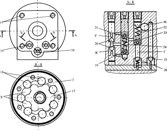
4 - pin, 5 - leaf spring, 6 - inner spool, 7 - external spool, 8 - body; 9 - bearing, 10 - drive shaft, 11 - splined sleeve, 12 - splined shaft, 13 - bolt, 14, 16 - screw plugs, 15 - threaded holes, 17 - satellite, 18 - rollers, 19, 20, 21, 23 , 25, 26 - valves, 22, 24 - springs
The servo valve consists of two hollow spools 6, 7 inserted into one another. Both spools are supported in the upper part on the drive shaft 10, while the inner 6 is connected to it by means of a protrusion I. The drive shaft, in turn, abuts against the housing through a thrust ball bearing 8. Its outer end has a radial hole for connection with the steering wheel shaft ... In the lower part, the outer spool 7 rests on the spacer plate 3 with a central hole, and the inner 6 on the sleeve 11, which is connected to the first rigidly pin 4. The inner spool 6 and the sleeve 11 are connected to each other by a diametrical spring plate 5. Thus, the spools, deforming plate 5, can rotate relative to each other in both directions by the amount of gaps F between the protrusion of the sleeve 11 and the groove of the inner spool 6.
The outer spool 7 in the upper part has an annular groove L with twelve paired holes coinciding in the neutral position with the same number of slots K in the upper part of the inner spool 6. Below, on the outer spool, six through holes H are drilled, always connected with the annular groove O of the inner spool , which, in turn, has six longitudinal slots P. Along the line of slots P in the lower part of the inner spool, six holes C are made, and between them - six slots E. Holes C and slots E are in a neutral position between the twelve holes T of the outer spool ... In the middle part, the outer spool has two rows of paired holes D and 3 (six in each), staggered opposite the annular grooves Ж and Р of housing 1.
The planetary pump is attached to the lower part of the body with bolts 13. It consists of a cage 2 with seven rollers 18, which form a stationary gear, and a rotating gear (satellite) 17. Spacer plate 3 and cage 2 with a cover 1, together with the satellite, form seven sealed chambers X. All chambers X are connected with L-shaped holes Y with the bottom of the outer spool 7.
The satellite 17 has six teeth of a radial profile and is driven by a splined floating roller 12 from the sleeve 11. When rotating, the satellite rolls over a cage with rollers with minimal clearances between the teeth, moving in an orbit.
In the holes in the metering pump housing there are valves necessary for the normal operation of the hydraulic system.
The safety valve 23 protects the gear pump from overpressure. The screw plug 14, acting on the spring 22, determines the moment of the safety valve actuation (16 MPa).
A spring-loaded check valve 26 prevents oil from flowing out of the system when the oil supply line breaks.
Shockproof valves 19 and 21 protect the hydraulic system from pressure surges when the wheels hit on uneven ground. The threaded plug 16, by changing the compression of the spring 24, regulates the response pressure of the anti-shock valves (21 MPa).
Anti-vacuum valves 20 feed the opposite cavities of the hydraulic cylinders when the anti-shock valves are triggered, which prevents cavitation.
The check valve 25 separates the discharge and discharge cavities when the gear pump is running. In the event of a gear pump failure, valve 25 allows the steering hydraulic system to operate by allowing oil from the drain line to flow into the suction cavity.
Threaded holes 15 are used to fasten the metering pump to the floor of the combine cab under the steering column.
Hydraulic system operation.The hydraulic steering system works as follows. With a non-rotating steering wheel (neutral position of the system), the gear pump pumps oil through the check valve (Fig. 8.70) into the central hole A of the inner spool 2. Then, through the grooves B of the inner spool and holes B of the outer spool 1, the oil goes to drain into the tank.
During the turning of the steering wheel, the drive shaft 3 transmits the torque to the inner spool 2. At this moment, all seven L-shaped holes AND are locked by spools and the satellite 4 is not able to turn. The leaf spring 6 is deformed, which allows the inner spool 2 to rotate at a certain angle relative to the outer 1 in the direction of rotation of the steering wheel (control torque no more than 5 Nm).

Figure 8.70. Scheme of the metering pump:
A - central cavity; B, E, M - grooves; V, G, 3, L, O - holes; Д, Ж - annular grooves; And - L-shaped holes; K, N - sealed cavities; 1 - external spool; 2 - inner spool; 3 - drive shaft; 4 - satellite; 5 - clip; 6 - leaf spring; 7 - valve
Slots B go away from holes C, cutting off the discharge cavity from the drain. In this case, twelve holes O of the outer spool 1 are connected with six holes 3 and six slots M of the inner spool 2 through one. L-shaped holes And are open.
In the position of the satellite 4 and the stationary gear 5, corresponding to the alignment of their axes of symmetry, the pump chamber is divided into two equal parts K and H, which form the pressure cavity (from the instantaneous center of rotation towards the rotation of the satellite) and suction. The cavities move with the satellite. The servo distributor communicates the pump suction cavity through holes 3 with the central discharge cavity A, and the pump discharge cavity turns out to be connected through the slots M and the holes L of the external spool with one of the annular grooves D or W of the working hydraulic cylinders (depending on the direction of rotation of the steering wheel). Another groove of the working hydraulic cylinders through the grooves E and holes D communicates with the drain line.
The amount of oil supplied from the metering pump to the hydraulic cylinders is proportional to the steering angle.
As soon as the rotation of the steering wheel is stopped, the leaf spring 6 returns the spools to the neutral position, the lines of the working hydraulic cylinders and the planetary pump are locked, and the oil pumped by the gear pump goes to drain.
In the absence of oil flow from the gear pump (emergency mode), the metering pump operates as a hand pump driven by the rotation of the steering wheel.
When changing the oil, it is necessary to remove air from the steering system by turning on the engine. The oil is warming up. The bodies of the hydraulic cylinders are disconnected from the beam of the axle of the steered wheels and unfold with the fittings upward, which facilitates the release of air from them. Turn the steering wheel. Hydraulic cylinder rods move 5-10 times from one extreme position to another.
Hydraulic system Combine harvester "Don-1500" consists of three independent hydraulic systems: main, volumetric steering and volumetric drive of the chassis.
The main one - performs many operations: raises (lowers) the header and the reel, changes the speed of the reel and threshing drum, moves the reel horizontally, turns the unloading auger into working and transport positions, turns on (off) the drive of the thresher and the unloading auger, makes reverse scrolling (reversing) the feeder house conveyor, closes the stacker and improves the discharge of wet grain from the hopper.
Given the multifunctionality and complexity of this system, it is often difficult to establish the causes of emerging failures and quickly eliminate them, especially in the field.
Long-term experience of work of the Tambov technical center "Agrotekhnika" (organized by VIITiN) in eliminating the consequences of failures made it possible to develop methods for finding their causes and ways of eliminating them. These methods are based on the principle of finding and eliminating the consequences of failures "from simple to complex" with the least laboriousness.
Search and elimination of the consequences of failures of the main hydraulic system must be carried out according to external signs their manifestations in the sequence shown in the table
| External manifestation of refusal and possible reasons | Identification and elimination of the consequences of failures | |
| All consumers of the hydraulic system do not work, there is no pressure in the system | ||
| Insufficient oil level in the hydraulic tank | Check the level according to the oil indicator in the tank, fill it up to the upper mark (oil M-10B2, M-8V GOST 8581-78, GOST 10541-78) | |
| Oil is not supplied to the pump NSh-32A-3 (increased pump noise) | ||
| The suction hose is pinched | Inspect the sleeve, eliminate pinching | |
| There is no spring inside the suction arm | Check the presence of the spring by touch. Insert the spiral spring with bent ends into the suction hose | |
| Loosening of the tensioning device of the pump drive NSh-32A-3 | Check the degree of tension, adjust the tension of the belts if necessary | |
| Pump NSh-32A-3 does not rotate | Check the temperature of the pipelines before and after the safety relief valve. If, after starting the engine, the pipes do not heat up for 15 minutes, check the condition of the pump drive (spline sleeve and circlip on the pulley) | |
| The safety-overflow valve (KPP) is not adjusted 108.00.000V | Check the gearbox actuation pressure. Adjust it by 1 25 ± 5 kgf / cm2. To do this, you need to rotate the bolt in the required direction (tightening - the pressure is more, unscrewing - the pressure is less). After adjustment, tighten the lock nut and seal the bolt. The valve setting should be done at the rated engine speed (2000 min- ") and oil temperature 50 °. | |
| Checkpoint clogged | Remove the discharge flange from the valve. If the oil flows from the gearbox in a continuous stream, then the valve is "stuck". Press the valves all the way down with the blunt end of the bit and release. The flow should be droplet. When performing operations, the tool must not fall into the valve-to-seat gap. | |
| The outer sealing washer (PTFE) of the gearbox bushing is out of order. The bushing is installed with the outer shoulder up | Disassemble and rinse the checkpoint. Check visually that the sealing washer is working properly. Replace washer if rupture or crushing or crushing of the washer is observed. Fit sleeve with ring correctly | |
| A foreign object (a piece of rubber, scale, shavings, etc.) gets under the checkpoint needle | Disassemble the safety part of the gearbox. Check for foreign objects. Flush the safety part with diesel fuel and, if necessary, adjust the actuation pressure of the gearbox (125 ± 5 kgf / cm2) | |
| Inoperative checkpoint | Perform the above operations. Without positive result replace the checkpoint | |
| Loss of pump performance NSh-32A-3 | If there is no pressure when replacing the gearbox, check the pump performance with a DR-90 throttle manufactured by GOSNITI. Replace pump if necessary | |
| Increased oil heating during system operation | ||
| Insufficient amount of oil in the hydraulic tank | Check the oil level in the hydraulic tank. Top up the hydraulic tank up to the upper mark of the oil indicator | |
| Hydraulic tank filter element dirty (635-1-06) | The filter clogged icon should light up in the cab. Replace filter element. Do not drain oil from the tank when changing the filter. (When the oil is cold, the filter clogged icon may light up, but it should go out as the oil warms up) | |
| Rapid heating and overheating of the oil when the hydraulic controls are off | ||
| The presence of constant pressure in the system (more than 10 kgf / cm) | Measure the pressure in the main hydraulic system at the checkpoint with the controls off | |
| The rods from the bar of the head drop sensor to the distributor of the stacker are not adjusted | Check linkage adjustment. With the stacker valve closed, the stacker distributor spool pusher should be fully extended (extreme right position) | |
| The spool of the distributor of the stacker is jammed | Check the movement of the pusher, having previously disconnected it from the rods. If it moves without effort, you need to disassemble, rinse with diesel fuel and find damage. If necessary, replace the stacker distributor | |
| The control rod of the mechanical distributor is clamped | Check the movement and ease of movement of the rods, eliminate detected jamming | |
| Mechanical valve spool not in neutral | Check the neutrality of the spool position with the neutral position of the control handle. Adjust the rods of the mechanical distributor | |
| Hydraulic valve stuck with electromagnetic control 109.00.000 | If the pressure in the main system does not decrease to 4 kgf / cm2 with the controls off, replace the electrohydraulic valve 109.00. | |
| Ejection of oil from the breather, foaming of oil in the hydraulic tank | ||
| Air leaks into the system | Check the condition (foaming) of the oil through the oil tank gauge glass. Retighten the suction flange on the pump, fittings and clamps for the oil suction lines. Replace damaged flange o-rings, damaged hoses | |
| Slow movement of working bodies at the rated engine speed | ||
| (at n \u003d 2000 min-1 and heated oil t \u003d 50 °) | ||
| Reduced pressure in the main hydraulic system due to gearbox misalignment | Adjust the gearbox to 125 kgf / cm2 and seal | |
| Slip of pump drive belts NSh-32A-3 | Check the tension of the pump drive belts | |
| Increased oil leaks in the pump NSh-32A-3 | Check the pressure in the system. If it is impossible to raise it at the checkpoint to 125 kgf / cm2, check and replace the pump | |
| Header does not lower | ||
| The risks on the spindle and the throttle valve body are not aligned | Check the alignment of the marks. Combine appropriate risk, heavier header - smaller choke diameter, lighter - more | |
| The locking device of the mechanical distributor in the header lift section does not drain the working fluid | Disassemble the locking device. Replace valve and bushing | |
| The header lifting handle in the cab rests against the panel | Check the stroke of the spool when moving the control handle. The spool travel should be ± 7 mm from neutral. Adjust the spool thrust | |
| Spontaneous lowering of the header (pick-up) | ||
| The locking device of the mechanical distributor in the header lifting section does not provide tightness | Disassemble the locking device. Replace valve, bushing or rubber ring | |
| Reel drive cylinders are out of sync | ||
| Air in hydraulic cylinders | Bleed air in the hydraulic system by alternately loosening the oil pipe fittings on the hydraulic cylinders | |
| No tightness of the shut-off device of the corresponding section of the mechanically controlled valve | Disassemble the locking device, replace sealing ring | |
| Internal oil leaks in hydraulic cylinders | Disassemble the right cylinder, replace the piston O-ring. After assembly, pump oil | |
| Reel variator hydraulic cylinder does not move moving pulley | ||
| Movable pulley not lubricated | Lubricate the pulley | |
| Reel speed does not change | ||
| A spring burst on a driven pulley | Check the functionality of the spring, if possible replace it | |
| Leakage on reel variator hydraulic cylinder spindle | ||
| Cuff rupture | Replace the cuff. Lubricate with oil before installation | |
| All consumers from the mechanical distributor work normally, but they do not work from the electrohydraulic distributors | ||
| Solenoid valve not working. No voltage | Check the voltage supply and the integrity of the ground wire at the contacts of the solenoid valve. In the absence of voltage, check the fuse links, the voltage on the keys and contacts with the buttons of the electrohydraulics panel, the integrity of the wiring and the contacts of the connecting chips of the electric circuit of the solenoid valve | |
| Solenoid valve not working. Voltage applied | Replace solenoid valve 109.00.000 | |
| One of the consumers of the electrical distributor section does not work | ||
| Voltage is applied simultaneously to two opposite coils of the distributor section | Check the serviceability of the VD-2 diode blocks in the electrohydraulics control panel. Replace defective unit | |
| No tightness of the seat and needle on the side opposite to the oil supply to the hydraulic cylinder | Disassemble the valve, see details. Lapping tapered surfaces or replace seat, rubber O-ring | |
| There is no voltage at the solenoid coil | Check voltage. Eliminate malfunction | |
| There is voltage on the coil of the electromagnet, but the armature does not "click" | Replace solenoid valve | |
| Large internal leakage in the piston cylinder | Apply pressure to one of the cavities of the hydraulic cylinder, the other must be open. The emergence of flow from an open cavity indicates a malfunction of the cylinder. Replace it | |
| The valve of the hydraulic distributor section is jammed in the extreme position | Switch on any other consumer of electrohydraulics. If the consumer in question is triggered, then the spool is jammed. Remove the distributor, replace the section | |
| The hydraulic lock piston is jammed in the extreme position | Unscrew the shut-off valves, check the free movement of the piston. Lapping piston. Rinse and insert it into the distributor | |
| Plugging the throttle hole of the spool sleeve | Disassemble, clean the throttling holes, rinse and assemble the section | |
INTRODUCTION
An important role in ensuring the quality of the implementation of the technological process of grain harvesting is played by the control systems of both individual working bodies of the combine harvester and the machine as a whole.
Modern combine harvesters are equipped with hydraulic, electric, electro-hydraulic and other automatic or manual control systems. They are used to change the vertical or horizontal position of individual working bodies and units, to turn on the drive and change the operating mode (decrease or increase the rotational speed, forward speed) of the working bodies and the machine, to facilitate maneuvering (turning the steered wheels), to increase the effectiveness of the impact on the processed material, etc.
Application in complex sweepers modern systems control allows you to quickly respond to changing harvesting conditions by timely and prompt changes in the corresponding technological parameters of the machine, and thus contributes to increasing the efficiency of the technological process.
As a result, the time for carrying out work on the regulation of the most frequently changed parameters is reduced, the comfort of machine control increases, and it becomes possible to automatically control the progress of the process and take into account its main indicators.
All this ensures an increase in the operational reliability of machines, the productivity of the harvesting units and the quality of the technological processes performed.
1. PURPOSE AND ORDER OF PERFORMANCE OF THE WORK
The aim of the work is to study the device and the principle of operation of the main hydraulic system of the combine harvester and the design features of the hydraulic systems of the steering and running gear drive. When performing laboratory work, you must:
1) using guidelines, posters and technical equipment, to study the structure and principle of operation of the main hydraulic system of the combine harvester Don-1500;
2) to study the main features of the design and working process of hydraulic systems of steering and drive of the chassis.
1. PURPOSE, COMPOSITION AND PRINCIPLE OF OPERATION OF THE MAIN HYDRAULIC SYSTEM
Combines "Don-1500" have three independent hydraulic systems: the main one, which ensures the performance of twelve operations to control the working bodies of the combine, the hydraulic system of the steering, which rotates the steered wheels and the hydraulic system of the chassis drive.
The main hydraulic system provides: lifting and lowering of the header, vertical and horizontal movement of the reel, reversal of the working bodies of the header when clogging with grain, turning on and off the drives of the thresher and unloading augers, turning the inclined unloading auger, controlling the variators of the reel and the threshing drum when changing their rotation frequency, switching on the vibrators of the hopper and control of the stacker.
It includes an oil reservoir with an oil filter, a gear pump NSh-32, a safety-overflow valve, an electromagnetic hydraulic valve, a mechanically controlled hydraulic valve, electromagnetic hydraulic valves, one-way and two-way hydraulic cylinders, a stacker distributor, a hopper vibrator, a throttling valve and a system hoses and oil lines.
A schematic diagram of the main hydraulic system and an oil flow diagram are shown in Fig. 1 and 2.
The safety and overflow valve 45 (Fig. 1) maintains the set pressure in the delivery lines of the system, the solenoid-controlled hydraulic valve5 blocks the control flow
when any section of the solenoid valve is switched on.
Hydraulic distributor 6 with mechanical control has five spool sections that serve the hydraulic cylinders: 7 - raising and lowering the header; 11 - reel variator; 12 and 13 - moving the reel in height; 14 and 15 - horizontal movement of the reel and 16 - threshing mechanism switching on.
The two-section distributor 22 with electromagnetic control serves the hydraulic cylinders 24 and 25, respectively, designed to reverse the working bodies of the header and turn on and off the drives of the unloading augers.
A three-section hydraulic valve 42 with electromagnetic control serves the hydraulic cylinders: 30 - control of the threshing drum variator; 32 - turning the unloading inclined auger; 38 - opening the stacker, as well as hopper vibrators 35 and 36. The stacker control valve 41 directs the oil flow into
Figure: 1. Schematic diagram of the main hydraulic system: 1 - tank, 2 - pump; 3, 4 - external platforms; 5 - hydraulic valve with electromagnetic control; 6 - hydraulic valve with mechanical control; 7 - hydraulic cylinders for lifting the header; 8 - throttles -
control valve; 9, 17, 19, 23, 26, 27, 28, 29, 31, 33, 34, 37 - chokes; 10, 18, 20, 21 -
couplings; 11 - hydraulic cylinder of the reel variator; 12, 13 - hydraulic cylinders for vertical movement of the reel; 14, 15 - hydraulic cylinders for horizontal movement of the reel; 16 - hydraulic cylinder of the thresher engaging mechanism; 22 - two-section hydraulic valve with electromagnetic control; 24 - hydraulic cylinder for scrolling the inclined chamber; 25 - drive hydraulic cylinder unloading augers; 30 - hydraulic cylinder of the threshing drum variator; 32 - hydraulic cylinder for turning the inclined unloading auger; 35, 36 - hopper vibrators; 38 - hydraulic cylinder for opening the stacker; 39, 40 - hydraulic cylinders for closing the stacker; 41 - control valve for the stacker; 42 - three-section hydraulic valve with electromagnetic control; 43, 44 - pipelines of the control channel; 45 - safety-overflow valve of the main hydraulic system; 46 - pipeline of the channel of connection with the steering system.
hydraulic cylinders 39 and 40 for closing the stacker valve. An adjustable throttling valve8 is installed in the oil supply line to the header lift hydraulic cylinders to change the speed of the header lifting and lowering.
Most oil lines are fitted with chokes
(9, 17, 19, 23, 26, 27, 28, 29, 31, 33, 34 and 37), limiting the
oil flow rate. The hoses for supplying oil to the reel control hydraulic cylinders are equipped with ball couplings that allow the lines to be disconnected without loss of oil when the header is removed from the combine and to connect these lines when the header is mounted on the combine.
The movement of the working fluid in the main hydraulic system can be subdivided (Fig. 2) into five flows: 2 - intake (suction) of oil by the pump; 10 - discharge from the pump; 9, 19, 20 - control; 13 and 18 - discharge of the discharge flow and 16 - discharge of the flow management.
With the engine running and all valve spool valves in the neutral position, oil from the tank flows to the pump1 and through the overflow channel 8 of the safety-overflow valve is drained back into the tank14 by flow13. Channel 8 is open to drain the flow 13
Figure: 2. Scheme of oil flows in the main system with the neutral position of the valve spool and the operating pump: 1 - pump; 2 - the flow of oil intake by the pump; 3 and 4 - two- and three-section electrohydraulic distributors; 5 - outlet from the control flow valve; 6 - safety valve; 7 - safety and overflow valve; 8 - overflow channel; 9, 19, 20 - control flows; 10 - discharge flow from the pump; 11 - throttle hole; 12, 13, 18 - working fluid drain flows; 14 - tank; 15 - stacker distributor; 16 - control flow drain; 17
- valve with electromagnetic control; 21 - valve spool; 22 - valve with mechanical 6 control.
only with control flows 9, 19 and 20, which ensure the constant opening of the bypass valve and pressure reduction
in discharge line.
WITH by moving the spool of one of the valves, the control flow is closed (in mechanically controlled valves - by a spool, in solenoid valves - by a hydraulic valve with electromagnetic control), the overflow valve closes, and the oil under pressure enters the corresponding hydraulic cylinders, performing work to control one of the above workers organs. To ensure smooth control processes, the rate of oil flow into the cylinders is limited by the presence of throttling holes in the lines.
The oil pushed out of the hydraulic cylinders is drained through the valve spools along the lines 12 or 18 into the oil tank. When coming from the drain line, the oil is cleaned by passing through an oil filter installed in the reservoir.
The main hydraulic system and the steering hydraulic system share a common oil tank located on the front wall of the hopper.
The oil tank is equipped with an oil level indicator. The tank is filled in such a way that when the header and reel are lowered, the hydraulic
Figure: 3. Filter of the reservoir of the main hydraulic system: 1 - valve assembly; 2 - filter element; 3, 7, 8, 10 and 14 sealing rings; 4 - retaining ring; 5 - body; 6 - signaling valve; 9 - bolt; 11 - plug; 12 - cover; 13 - tip; 15, 19 and 21 - washers; 16 and 18 - springs; 17 - axis; 20 - cotter pin; 22 - valve.
the cylinders of which are the most voluminous, the oil level corresponded to the upper mark on the level scale.
In the upper part of the tank there is a breather for connecting the inside of the tank to the atmosphere, which ensures a constant pressure in the tank regardless of the oil level. In the lower part of the tank there are two tips for connecting to the suction lines of the hydraulic systems and a fitting for draining the oil.
An oil filter is bolted to the bottom of the tank (Fig. 3). A tip 13 is screwed into the filter housing 5, to which the oil line of the drain line is connected. Coming from

on this line, the oil goes to the tank through the filter element 2 and valve 1. If the filter element is excessively clogged or, for other reasons, the pressure in the drain line rises to 0.25 MPa, the signaling valve 6 is triggered and all or part of the oil is drained through this valve into the tank without filtration. In this case, a sound signal is activated in the cab.
flow rate 55.6 l / min. The pump is driven by a V-belt double-strand transmission from the engine crankshaft.
Safety relief valve maintains the required operating pressure in the system (12.5 MPa) and thereby protects the system from emergency overloads.
The main parts of the valve (Fig. 4) - body 1 with five cavities: discharge A, throttle valve B, control flow outlet B, safety valve D and drain M; safety valve3 with adjustment screw4, piston7 with throttling hole8 and springs2 and5.
Cavities A and D are separated by a piston 7 and a valve 3, which are held by springs 2 and 5, respectively. At the same time, cavity A is connected to cavity B and C through the throttle hole 8. Cavities
and D are communicated through the |
|||||
cash 6. | |||||
At pressure in the system |
|||||
injection, exceeding |
|||||
nominal, |
|||||
incoming | |||||
cavities B and C through the throttling |
|||||
hole 8, | |||||
valve 3, pre- |
|||||
overcoming | resistance |
||||
springs 5. This leads |
|||||
pressure drop in the |
|||||
lost B and | B. Given |
||||
difference | checkpoints | ||||
holes 8 and | |||||
openings of the valve |
|||||
3 pressure on the piston |
|||||
Figure: 4. Safety relief valve: 1 - | from the side of cavity A bu- |
||||
body; 2 and 5 - springs; 3 - safety valve | children more than a hundred |
||||
pan; 4 - screw; 6 - channel; 7 - piston; 8 - throttles- | cavity B, therefore |
||||
opening hole; A - discharge cavity; B - za- | piston 7 moves, |
||||
throttle cavity; B - flow outlet cavity | compressing the spring 2, and |
||||
management; Г - cavity of the safety valve; | oppressive | cavity A |
|||
D - drain cavity. | |||||

directly connected to the drain cavity When the pressure drops in the discharge cavity A (and, accordingly, in the cavities B and C), the spring 5 closes the valve 3. In the absence of a control flow (oil draining from cavity C), the pressure in cavities A, B and C is equalized and the spring2 returns the piston 7 to its original position, separating the pressure cavities A and drain D. In the presence of a control flow (all spools are in neutral position) due to the throttle hole, a pressure difference in cavities A and B is provided, and the piston remains open until the control flow is cut off when any of the spools is turned on.
The pressure at which the safety valve3 operates depends on the compression ratio of the spring5, which is adjusted with the screw4. Working pressure 12.5 MPa.
Hydraulic valve with electromagnetic control, which over-
closes the control flow when one of the sections of the electric
hydraulic distributor, consists of (Fig. 5) | from building 1 | |||||
the carcass of the electromagnet 8. Inside the body there is an anchor 10, in which | ||||||
there is a needle 9, a pusher 11 and a spring 13. With neutral | ||||||
position of all spools of electro-hydraulic valves |
||||||
oil is pumped into channel B of the hydraulic valve. The created pressure is | ||||||
relocates | ||||||
overcoming | ||||||
resistance | ||||||
women 13, as a result | ||||||
what channelB | ||||||
connects | ||||||
cash A, skip | ||||||
terminal 3 in the coil | ||||||
arrives | ||||||
electric | ||||||
Figure: 5. Hydraulic valve with electromagnetic control: | emerging |
|||||
while the force ne- | ||||||
1 - case; 2 - sleeve; 3 - terminal; 4 and 7 - screws; 5 - washer; 6 and | moves anchor 10, | |||||
17 - nuts; 8 - coil; 9 - needle; 10 - anchor; 11 - pusher; 12 | ||||||
and 14 - sealing rings; 13 - spring; 15 - ring; 16 - | ||||||
retaining ring; 18 - bushing; A - output channel: B - input- | ||||||
noah channel. | united | |||||
oppressive | ||||||
lost B. The control flow disappears, the drain channel of the safety-overflow valve is closed, and all oil from the pump is directed to the corresponding cavity of the hydraulic cylinder.
Mechanically controlled hydraulic valve (fig. 6)
includes five independent spool sections. The oil enters the distributor through the discharge channel E. The upper and lower drain channels D, passing through all spool sections, are connected by a channel I located in the cover 7. The control flow channel G also passes through all spool sections and connects to holes 6 and 43 in covers 7 and 42. Each section has a spool 15, check valves 16 and 26 and a piston 24 and is connected to the hydraulic cylinder through holes 17 and 27 in the outer sleeves of the check valves. The fourth and sixth sections, respectively, associated with the hydraulic cylinders of the horizontal movement of the reel and the threshing mechanism, have two shut-off valves, and the other three sections - one each, since in the first case, double-acting piston cylinders are used, and in the second, single-acting plunger cylinders ...
The neutral position of the spool is fixed by a spring28 and the annular grooves on it in this position are aligned with the main channels passing through the bodies25 of all sections.
The shut-off valves connect or disconnect the cavities of the hydraulic cylinder with the annular cavities Zh.
When the spool is in the neutral position, the oil flows through hole 43 in the cover 42 into channel D and is drained through hole 6 in the cover 7, providing control flow, and the oil supplied by the pump is drained back into the tank through the open drain channel of the safety-overflow valve.
When the spool moves, the control channel G is closed, and the delivery E and drain D channels are connected to the corresponding cavities of the hydraulic cylinder. The principle of connection is such that if one of the cylinder cavities (for a double-acting hydraulic cylinder) is connected to the discharge channel, then the opposite one is connected to the drain channel. The control flow disappears and the overflow relief valve closes. The oil from the pump is directed to the desired cylinder cavity through channel E and the upper or lower check valve. Piston 24 moves to open the opposite (lower or upper) valve, allowing oil from another cylinder cavity to flow into the return line
When turned off, the spool returns to the neutral position automatically by the action of spring 28
Hydraulic valves with electromagnetic control
they are filled in the form of three-section and two-section units, the first of which controls the hydraulic cylinders of the threshing-slave variator, the unloading auger rotation and the hopper vibrator, and the second - the hydraulic cylinders for reversing the header working bodies and the unloading augers drive mechanism.

Fig. 6. Hydraulic valve with mechanical control: 1, 2, 3, 4 and 5 - working sections; 6 - opening for draining the control flow; 7, 31, 42 - covers; 8 - bolt; 9, 10, 14, 20, 23, 35, 36 - sealing rings; 11 - hole for draining oil from the hydraulic distributor; 12 - nut; 13 - plug; 15 - spool; 16 and 26 - stop valves; 17 and 27 - holes for directing oil flow into the hydraulic cylinder or from the hydraulic cylinder; 18 and 39
- crosses; 19, 28 and 38 - springs; 21 and 34 - valves; 22, 32, 37 - washers; 24 - piston; 25 - section body; 29 - spacer sleeve; 30 - circlip; 33 - sleeve; 40
- fitting; 41 - hole for pumping oil into the valve E; 43 - hole for selection of the control flow; G, D, E and I - valves; Zh - cavity.
Three-piece solenoid valve shown in
fig. 7. The main parts of the distributor: working sections 3, 4 and 6, covers 1 and 9 and electromagnetic attachments10. The valve spool sections that control the single-acting hydraulic cylinders are equipped with one, and the double-acting ones - two shut-off valves. In the absence of significant loads on the controlled hydraulic cylinder at the neutral position of the spool, the section is made without shut-off valves. The spool body has channels B, V and D and in the covers - channels E and K. ChannelsB andE - injection, channelsD - drain, connected through channelK. Channel B connects the IH cavities of the solenoid valve and the spool.
The hydraulic cylinders are connected to the annular cavities through the shut-off valves. There is a piston 21 in the bridge between the check valves.
neutral | position | spools are held | springs |
|||||
25. Solenoid valves 33 under the action of springs 35 | ||||||||
holes 32, | uncoupling discharge | channel B with | cavity I. |
|||||
Served | merges | safety- |
||||||
overflow valve of the hydraulic system to the tank. | ||||||||
After pressing the corresponding button on the control panel, a current flows through the coil of the electromagnetic attachment, creating an electromagnetic induction force. Under its influence, overcoming the resistance of spring 35, valve 33 moves (in the figure to the right) and opens hole 32, passing oil from channel B through cavity I and channel B into cavity D. Under oil pressure, the spool moves (to the left in the figure), overcoming the resistance of the spring25 and displacing the oil from the opposite cavity D through the throttle hole in the spool into the drain channel. Discharge channel B through the annular groove of the spool is connected to one of the cavities (left in the figure) between the check valve and the piston, while the opposite cavity is connected to the drain channel. The generated oil pressure opens the check valve, allowing oil to flow into the corresponding cylinder cavity, and moves the piston, which opens the opposite valve to drain oil from the opposite cylinder cavity.
After disconnecting the current from the electromagnetic attachment, the spool returns to the neutral position under the action of the springs, and the valves close.
Stacker distributor(fig. 8) consists of body1, spool3, pusher6, covers9 and15 and spring11.
The opening of the stacker chamber latches is carried out by a hydraulic cylinder controlled by one of the spools of the electromagnetic three-section distributor, and the stacker distributor provides only automatic closing of the stacker chamber after it is freed from the shock. Therefore, in the process of forming a shock and its - you
The invention relates to agricultural mechanical engineering and can be used in control systems for the executive mechanisms of grain harvesters. The hydraulic system contains a hydraulic tank connected to the pump, pressure and discharge hydraulic lines, hydraulic actuating motors of various energy capacities and electromagnetic control valves. The hydraulic system has electromagnetic and safety valves. The solenoid valves are connected in series to the control line of the overflow valve, and the safety valves are connected in parallel. A safety valve is connected upstream of each solenoid valve and is set to a lower pressure than the previous safety valve. The use of a device of several pressure levels in the hydraulic system of a combine harvester makes it possible to reduce energy consumption for the operation of its hydraulic drives. 2 wp f-ly, 2 dwg
Drawings for RF patent 2398374
The invention relates to agricultural machinery, in particular to grain harvesters.
Known hydraulic system, adopted as an analogue (Combine harvesters Yenisei. Self-propelled combine harvester "YENISEI KZS 950" and its modifications. Operation manual. OJSC PO KZK, 2004, GOSNITI SF, 2004, p. 10, 54-59 Patent No. 2210202 "Hydraulic system of a combine harvester" 08/20/2003), in which a device of two pressure levels is used, including pressure and discharge hydraulic lines, executive hydraulic motors of various power capacities, electromagnetic control valves for them, a pump, a hydraulic tank, a hydraulically controlled overflow valve, integrated into one block with a three-position solenoid valve connected in series to the control line of the overflow valve, connecting one safety valve to the control line in one position to two safety valves in the other.
The disadvantage of the hydraulic system is that the use of a known device of two pressure levels, controlled by a three-position slide valve, is not sufficient for rational use in the hydraulic system of the hydraulic actuators of the working mechanisms of the combine of low energy intensity. The three-position valve limits the possibility of introducing an additional pressure circuit into the device with a minimum setting of the operating pressure.
Known hydraulic system of a combine harvester (Patent No. 2210203 "Hydraulic system of a combine harvester" 08/20/2003), adopted as a prototype, in which a device of two pressure levels is used, including injection and discharge hydraulic lines, executive hydraulic motors of various energy intensity, electro-hydraulic distributors and distributors with mechanical controlled, pump, hydraulic tank, hydraulically controlled overflow valve, combined in one block with electromagnetic, two safety valves and a working section of an electro-hydraulic distributor.
The disadvantage of the hydraulic system is that the use of a mechanical distributor and its connection to the control line of the overflow valve increases the resistance in it, which leads to an increase in the opening pressure of the overflow valve and limits the functional capabilities of the development of the unit, including overflow, safety and electromagnetic valves, the working section of the electrohydraulic distributor according to introduction of additional pressure circuits.
The technical result of the invention is expressed in expanding the functionality of the hydraulic system, increasing its efficiency. This is achieved by the fact that the hydraulic system of the combine harvester contains pressure and discharge hydraulic lines, actuating hydraulic motors of various energy capacities, electromagnetic control valves for them, a pump, a hydraulic tank, a hydraulically controlled overflow, electromagnetic and safety valves, while the hydraulic system is equipped with solenoid valves connected in series to the overflow valve control line and safety valves connected in parallel to it, and the safety valve is connected in front of each solenoid valve with a setting of lower pressure than the previous one, while the overflow, safety and solenoid valves are made in one block in the form of sections interconnected by channels: drain, control, moreover, in the first section there are overflow and safety valves, in the second section the solenoid valve and the second safety valve, set to a lower pressure than the safety valve the first section, in the third section and subsequent electromagnetic and safety valves, made like the second section, in the last section there is a solenoid valve.
Comparative analysis with the prototype shows that the claimed device differs in that the hydraulic system is additionally equipped with solenoid valves connected in series to the control line of the overflow valve, and safety valves connected in parallel to it, and the safety valve is connected in front of each solenoid valve with a lower pressure setting than the previous one, while the overflow, safety and solenoid valves are made in one block in the form of sections interconnected by channels: drain, control, in the first section there are overflow and safety valves, in the second section the solenoid valve and the second safety valve, set to a lower pressure than the safety valve of the first section, in the third section and subsequent electromagnetic and safety valves are made as the second section, in the last section there is a solenoid valve. Verification of compliance of the claimed invention with the requirement of an inventive step showed that the invention does not follow explicitly for a specialist from the prior art, since from the latter, the influence of the transformations prescribed by the invention, characterized by essential features distinguishing from the prototype, on the achievement of the technical result was not revealed.
Figure 1 shows a schematic diagram of the hydraulic system of a combine harvester; figure 2 shows a structural diagram of a unit including overflow, safety and electromagnetic valves.
The hydraulic system of the combine harvester contains a tank 1, to which pump 2 is connected, into the pressure line 3 of which unit 4 is connected. Through channel 5 of unit 4, pump 2 is connected to the overflow valve 6 and the first safety valve 7, located in the first section 8, unit 4. Drain Channel 9 of the overflow 6 and safety 7 valves is connected to the tank 1 through the drain line 10 and the filter 11. Sequentially, two-position two-way solenoid valves 13, 14, 15 are connected to the control channel 12 of the overflow valve 6. In parallel, to the control channel 12, in front of the solenoid valve 14, connected to a safety valve 16, set at a lower pressure than the first safety valve 7, and connected to the tank 1 through the drain channels 17, 9, hydraulic line 10 and filter 11. Solenoid 13 and safety 16 valves are located in the second section 18 of block 4. Parallel to control channel 12, before the solenoid valve 15, a safety valve is connected 19, adjusted to a lower pressure than the safety valve 16, and connected to the tank 1 through drain channels 20, 9, hydraulic line 10 and filter 11. Solenoid 14 and safety 19 valves are located in the third section 21 of block 4. Solenoid valve 15 is located in the last section 22 of block 4 and is connected to the tank 1 through drain channels 23, 20, 9, hydraulic line 10 and filter 11. In parallel, electromagnetic distributors 25, 26, 27 are connected to the pressure hydraulic line 3 of the pump 2 through hydraulic line 24. Electromagnetic valve 25 is connected through hydraulic line 28 with executive hydraulic cylinders 29, for example, the header lowering lifting mechanism (the most energy-intensive working mechanism). The hydraulic cylinders 29 are connected to the tank 1 through a hydraulic line 28, a hydraulically controlled shut-off device 30, a distributor 25, including a shut-off valve 31, a plunger 32, a drain channel 33 of a distributor 25, drain lines 34, 10 and a filter 11. The electromagnetic distributor 26 is connected through hydraulic lines 35, 36 with an executive hydraulic cylinder 37, for example, a drum reverse scrolling mechanism, which has a working stroke when the rod is extended during the reverse rotation of the drum and an idle stroke when the rod is returned to its original position. At the same time, the working stroke of the mechanism is also the most energy-consuming, and the idle stroke of the mechanism is the least energy-consuming in the hydraulic system of a combine harvester. Hydraulic cylinder 37 is connected to tank 1 through hydraulic lines 35, 36, drain channel 38 of distributor 26, drain lines 39, 10 and filter 11. The electromagnetic distributor 27 through hydraulic lines 40, 41 is connected to the actuating hydraulic cylinder 42, for example, to activate the mechanism of the tensioner of the belt drive of the thresher drive. The rod and plunger cavities of the hydraulic cylinder 42 are connected to the tank 1 through hydraulic lines 40, 41, a hydraulically controlled shut-off device 43, a distributor 27, which includes stop valves 44, 45, a plunger 46, a drain channel 47 of a distributor 27, drain lines 39, 10 and a filter 11. Design of the thresher drive belt tensioner mechanism (conventionally not shown), which has been used recently, implies a decrease in force when the mechanism is turned on to protect the belt drive from belt overtension, the possibility of adjusting the belt drive tension by applying adjustable pressure and creating optimal conditions for its reliable operation.
The device works as follows.
In the neutral operating mode of the hydraulic system, the working fluid from tank 1 by pump 2 is supplied through the pressure hydraulic line 3 to block 4 and then through the pressure channel 5 of the first section 8 it flows to the overflow valve 6 and safety valve 7. With the neutral position of the solenoid valves 13, 14, 15, part of the working fluid enters the tank 1 through the control line 12 of the overflow valve 6, through the solenoid valves 13, 14, 15 drain channels 23, 20, and 9 of block 4, the drain line 10 and the filter 11 Overflow valve 6 opens and the main oil flow from pump 2 enters tank 1 through drain channel 9 of block 4, drain line 10 and filter 11.
When an electrical signal is supplied from the control panel (conventionally not shown) simultaneously to the electromagnetic distributor 27 and the solenoid valve 15 of unit 4, the spool of the electromagnetic distributor 27 is removed from the neutral position to the position "Thresher switching on", and the electromagnetic valve 15 locks the drain of the working fluid into tank 1 through control port 12 of the overflow valve 6. The overflow valve 6 closes. The full flow of the working fluid under pressure from the pump 2 through the pressure hydraulic lines 3, 24 enters the electromagnetic valves 25, 26, 27 and directly to the hydraulically controlled shut-off device 43 of the distributor 27, moves the plunger 46 and opens the shut-off valve 45, connecting the rod cavity of the hydraulic cylinder 42 through the hydraulic line 40, open shut-off valve 45, drain cavity 47 of distributor 27, drain lines 39, 10 and filter 11 with tank 1. Then, the working fluid under pressure through the shut-off valve 44 through the hydraulic line 41 is supplied to the plunger cavity of the hydraulic cylinder 42, activating the thresher. After extending the rod of the hydraulic cylinder 14, turning on the thresher and tensioning the belt transmission belts to a certain moment, the safety valve 19 is triggered, set to the minimum pressure. At this moment, the movement of the rod of the actuating cylinder 42 is stopped, eliminating the tension of the belt drive belt.
When the electrical system is turned off and the spools of the distributor 27 and the solenoid valve 15 are returned to their original position, the hydraulic system operates in neutral mode. At this moment, the loaded plunger and non-load bearing rod cavities of the actuating hydraulic cylinder 42 are reliably disconnected from the tank 1 by shut-off valves 44, 45, which ensures belt tension and stable operation of the belt drive.
When an electrical signal is supplied from the control panel simultaneously to the electromagnetic distributor 27 and the solenoid valve 15 of block 4, the spool of the electro-hydraulic distributor 27 is moved from the neutral position to the position "Thresher shutdown", and the solenoid valve 15 locks the drain of the working fluid into the tank 1 through the control channel 12 of the overflow valve 6. Overflow valve 6 closes. The full flow of the working fluid under pressure from the pump 2 through the pressure hydraulic lines 3, 24 enters the electromagnetic valves 25, 26, 27 and directly to the hydraulically controlled shut-off device 43 of the distributor 27, moves the plunger 46 and opens the shut-off valve 44, connecting the plunger cavity of the hydraulic cylinder 42 through the hydraulic line 41, open shut-off valve 44, drain cavity 47 of distributor 27, drain lines 39, 10 and filter 11 with tank 1. Then, the working fluid under pressure through the shut-off valve 45 through hydraulic line 40 is fed into the rod cavity of the hydraulic cylinder 42, shutting down the thresher. After returning the rod of the hydraulic cylinder 42 to its original position, the safety valve 19 is triggered, set to the minimum pressure.
When the electrical system is turned off and the spools of the distributor 27 and the solenoid valve 15 are returned to their original position, the hydraulic system operates in neutral mode. At this moment, the plunger and rod cavities of the actuating hydraulic cylinder 42 are disconnected from the tank 1 by the shut-off valves 44, 45 of the hydraulically controlled shut-off device 43, ensuring a reliable shutdown of the thresher.
In the case of a slight elongation of the belt transmission belts and an increase in their length, the tension of the belts is compensated by an increase in the stroke of the rod of the hydraulic cylinder 42 when the thresher is turned on. After long-term operation of the combine and slipping of the belt drive belts, the force of the hydraulic cylinder 42 increases by adjusting the safety valve 19.
Thus, for the operation of the hydraulic drive for switching on the mechanism of the tensioner of the thresher drive belt drive, the minimum setting pressure of the safety valve 19 is used, the slight stretching of the belt drive belts is compensated by increasing the stroke of the hydraulic cylinder rod, if necessary, the tensioning force of the belts is adjusted by setting the safety valve 19, while the functioning of the hydraulic drives the hydraulic system is not disturbed. When an electrical signal is supplied from the control panel simultaneously to the solenoid valve 25 and the solenoid valve 13 of unit 4, the spool of the solenoid valve 25 is moved from the neutral position to the "Raise the header" position, and the solenoid valve 13 locks the drain of the working fluid into the tank 1 through the control channel 12 of the overflow valve 6. Overflow valve 6 closes. The full flow of the working fluid under pressure from the pump 2 through the delivery lines 3, 24, enters the electromagnetic distributors 26, 27, 25 and directly to the hydraulically controlled shut-off device 30 of the distributor 25, moves the plunger 32 and through the check valve 31, the hydraulic line 28 is supplied to the plunger hydraulic cylinders 29 while lifting the header. After the full exit of the rods of the hydraulic cylinders 29, the high pressure safety valve 7 is triggered.
When the electrical system is disconnected and the spool valves 25 and the solenoid valve 13 are returned to their original position, the hydraulic system operates in neutral mode. At this moment, the plunger cavities of the actuating hydraulic cylinders 29 are disconnected from the tank 1 by the shut-off valve 31 of the hydraulically controlled shut-off device 30.
When an electrical signal is supplied from the control panel simultaneously to the electromagnetic distributor 25 and the solenoid valve 14 of unit 4, the spool of the electromagnetic distributor 25 is moved from the neutral position to the "Lowering the header" position, and the solenoid valve 14 locks the drain of the working fluid into the tank 1 through the control channel 12 of the overflow valve 6. Overflow valve 6 closes. The full flow of the working fluid under pressure from the pump 2 through the pressure hydraulic lines 3, 24 enters the electromagnetic distributors 25, 26, 27 and directly to the hydraulically controlled shut-off device 30 of the distributor 25, acting on the piston 32, as a result of which the latter, moving, opens the shut-off valve 31 connecting the plunger cavities of the hydraulic cylinders 29 with the tank 1. The working fluid from the two plunger hydraulic cylinders 29 by the force of the weight of the harvesting part through the open shut-off valve 30 enters the drain cavity 33, the distributor 25, through the drain lines 34, 39 into the drain line 10, where, connecting with by the full flow of working fluid from pump 2, entering through the safety valve 16, adjusted to a lower pressure than the safety valve 7, drain channels 17, 9 of block 4, through the filter 11, it is drained into tank 1.
When the electrical system is turned off and the spools of the distributor 25 and the solenoid valve 14 are returned to their original position, the hydraulic system operates in neutral mode.
Thus, for the operation of the hydraulic drive in the "Raise the header" position, the setting pressure of the safety valve 7 is used, and for the operation of the hydraulically controlled shut-off device 30 of the distributor 25 (opening of the shut-off valve 31) when lowering the header, the setting pressure of the safety valve 16 is used, which is less than the setting of the safety valve 7 ...
In case of clogging of the thresher drum of the combine harvester with the grain mass, the thresher is switched off, and the drum reverse scrolling mechanism is connected to the drum shaft (conditionally not provided). The electrical signal from the control panel is simultaneously supplied to the electromagnetic distributor 26 and the solenoid valve 13 of unit 4, the spool of the electromagnetic distributor 26 is moved from the neutral position to the operating position "Drum roll", and the electromagnetic valve 13 locks the drain of the working fluid into the tank 1 through the overflow control channel 12 valve 6. Overflow valve 6 closes. The full flow of the working fluid under pressure from the pump 2 through the pressure hydraulic lines 3, 24 enters the electromagnetic distributors 25, 27, 26 and through the hydraulic line 35 is directed into the plunger cavity of the hydraulic cylinder 37, carrying out the working stroke of the drum reverse scrolling mechanism. At this moment, the plunger cavity of the hydraulic cylinder 37 is connected to the pump 2 and to the safety valve 7, adjusted to a higher pressure, and its rod cavity through the hydraulic line 36, the drain cavity 38 of the distributor 26, the drain lines 39, 10 and the filter 11 is connected to the tank 1. After full exit of the rod of the hydraulic cylinder 37, the high pressure safety valve 7 is triggered, the electrical system is briefly disconnected and the hydraulic system starts to work in idle mode. Then, an electrical signal is simultaneously supplied to the electromagnetic distributor 26 and the solenoid valve 15 of unit 4, the spool of the electromagnetic distributor 26 is moved from the neutral position to another operating position "Idle drum rotation", and the electromagnetic valve 15 locks the drain of the working fluid into the tank 1 through the control channel 12 overflow valve 6. Overflow valve 6 closes. The full flow of the working fluid under pressure from the pump 2 through the pressure hydraulic lines 3, 24 enters the electro-hydraulic distributors 25, 27, 26 and through the hydraulic line 36 is directed to the rod cavity of the hydraulic cylinder 37, carrying out the idling of the drum reverse scrolling mechanism. At this moment, the rod cavity of the hydraulic cylinder 37 is connected to the pump 2 and to the safety valve 19, set to the minimum pressure, and its plunger cavity through the hydraulic line 35, the drain cavity 38 of the distributor 26, the drain lines 39, 10 and the filter 11 is connected to the tank 1. B at the end of the idle stroke of the hydraulic cylinder 37, due to the lack of load, a sharp change in the speed of movement of the working fluid occurs, which leads to pressure overshoots, which depend on the setting value of the safety valve 15, set to the minimum pressure in comparison with the safety valves 7 and 16. After the rod returns to its original position, the electrical system is turned off and the hydraulic system begins to work in idle mode. If necessary, the operating cycle of the drum reverse scrolling mechanism is repeated until the drum is completely cleaned.
Thus, the use of devices of several pressure levels in the hydraulic system of a combine harvester through the use of overflow, safety and electromagnetic valves arranged in one block will reduce energy consumption for the operation of its hydraulic drives, increase the functionality of the hydraulic system as a whole and simplify its design.
CLAIM
1. The hydraulic system of a combine harvester, containing injection and discharge hydraulic lines, hydraulic motors of various energy capacities, control valves for them, a pump, a hydraulic tank, a hydraulically controlled overflow, electromagnetic and safety valves, characterized in that the hydraulic system is equipped with solenoid valves connected in series to the control line of the overflow valve, and safety valves connected in parallel to it, while the safety valve is connected in front of each solenoid valve with a setting lower than the previous one.
2. The hydraulic system according to claim 1, characterized in that the overflow, safety and electromagnetic valves are made in one block in the form of sections interconnected by channels: drain, control.
3. The hydraulic system according to claim 1 or 2, characterized in that in the first section there are overflow and safety valves, in the second section there is a solenoid valve and a second safety valve adjusted to a lower pressure than the safety valve of the first section, in the third section and subsequent solenoid and safety valves are made as the second section, in the last section there is a solenoid valve.


