REGULATORY METHOD FOR CALCULATING HEAT LOSSES THROUGH GUARDING STRUCTURES
Lecture 8. The purpose of the lecture: Calculation of the main and additional heat losses through various enclosing structures.
Estimated heat loss through the barriers are determined by a formula that takes into account the main heat loss in a stationary mode and additional, determined in fractions of a unit from the main ones:
Figure 4 Example of vertical dimensions. Due to the use of external dimensions, the heat transfer coefficient of the thermal bridge can be negative. This is because the relationship of external losers is considered “in the double”. The difference is also related to the loss of heat through the ground. The simplified method involves the use of tables or graphs for individual cases.
Heat losses between heated spaces at different temperatures. Due to the introduction of the term “heat loss calculation factor”, which is multiplied by the difference in internal and external temperature, in the event of heat loss to a space with a different temperature than the external temperature, a temperature reduction factor is required. This ratio is calculated as follows. The reduction factor is determined by the following equation.
Q ogr \u003d å (F i / R about i pr) (t p - t n) n i (1 + åb i), (6.1)
where R about i pr - reduced resistance to heat transfer of the fence, taking into account the heterogeneity of layers in the thickness of the wall structure (voids, ribs, ties);
n i - coefficient taking into account the actual decrease in the calculated temperature difference (t p - t n) for fences that separate a heated room from an unheated one (basement, attic, etc.). Determined by SNiP "Construction heat engineering";
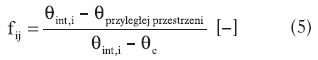
Table 3 Temperature of adjacent heated rooms. Table 4 Minimum air exchange rate. A big change introduced by the new standard is to take into account when calculating the heat load of individual rooms with heat loss to rooms of the same function, but belonging to a different division of the building. As a result, the temperature difference was 0 K and the heat loss was 0 W. This approach was justified at a time when it was almost impossible to individually adjust the internal temperature.
b i - coefficient taking into account additional heat loss through the barriers;
F i - area of \u200b\u200bthe fence;
t p - the room temperature, when calculating in conditions of convective heating, take t p \u003d t in , which is given in SNiP for a working area with a height of up to 4 m.In industrial premises with a height of more than 4 m, due to the uneven temperature in height, it is taken: for the floor and vertical fences to a height of 4 m from the floor - the normalized temperature in working area t p.z; for walls and windows located above 4 m from the floor - the average air temperature along the height of the room: t cf \u003d (t p.z + t in) / 2; for covering and skylights - air temperature in the upper zone t v.z (with air heating 3 ° C higher than the temperature in the working area); in other cases: t v.z \u003d t p.z + D (h - 4);
However, this calculation method is no longer adequate. Obligation to provide individual setting, and users often use this option, for example, by lowering the room temperature when they are away from the room. In the current economic and social situation, it is becoming more common that users have more than one apartment and some apartments are not used for shorter or longer periods. Then, especially in the case of an individual calculation of heating costs, the temperature in the apartment decreases relative to the calculated temperature.
t n \u003d t n 5 - design temperature of the outside air for heating.
Heat transfer between adjacent rooms is taken into account only when the temperature difference in them is 3 degrees or more.
6.1.1 Determining the temperature in an unheated room
Usually, the temperature in unheated rooms is not calculated to determine heat loss. (Heat loss is determined by the above formula (6.1) taking into account the coefficient n).
Therefore, in practice, there is often a temperature difference on both sides of the building barrier, although in the current model the temperature in both rooms was the same. As a consequence, the inner walls are usually not insulated, even if the temperature difference is relatively low, there can be significant heat loss. According to the author, it is also desirable to isolate the heat from the internal heat that separates the heated rooms if these rooms belong to separate building blocks. This insulation should be made of a material that, in addition to thermal insulation, has the property of soundproofing.
If necessary, this temperature can be determined from the heat balance equation:
Heat loss from heated to unheated premises:
Q 1 \u003d å (F 1 / R 1) (t in - t nx);
Heat loss from unheated premises:
Q 2 \u003d å (F 2 / R 2) (t nx - t n);
where t nx - the temperature of the unheated room (vestibule, basement, attic, lantern);
According to the new standard, the temperature in the adjacent room depends on the destination only if it belongs to the same building. On the other hand, if the room belongs to another device, the arithmetic mean of the predicted indoor temperature and the annual average outdoor temperature are used to calculate the heat loss. On the other hand, when the adjoining room belongs to a separate building, the average annual temperature is assumed to be outside. Without assessing the accuracy of this calculation method at this location, it can be argued that it allows the selection of radiators - at least in an approximate way - to take into account the risk of a decrease in indoor temperature in adjacent building units.
å R 1, åF 1 - coefficients of resistance to heat transfer and the area of \u200b\u200binternal fences (wall, door);
å R 2, åF 2 - coefficients of resistance to heat transfer and the area of \u200b\u200bexternal fences (external doors, walls, ceiling, floor).
6.1.2 Determination of the design surface of the fence
The area of \u200b\u200bthe fence and the linear dimensions of the fences are calculated on the basis of regulatory guidelines, which, when using the simplest formulas, make it possible to take into account, to a certain extent, the complexity of the heat transfer process.
It should also be emphasized that the heat losses described above are included in the calculation of the heat load of individual rooms for the selection of heaters, but they are not taken into account when determining the heat load of the entire building in order to select a heat source. On a building-wide scale, if some of the rooms are heated in a weakened manner, the excess capacity thus obtained will cover the increased demand for heat in the adjacent rooms. Also how to determine heat loss during heating.
In most typical buildings up to 10 m in height, the minimum air volume required for hygienic reasons is decisive. The minimum amount of air required for hygiene reasons for a heated space is as follows.
The measurement scheme for the barriers is shown in Figure 6.1.
The first step in organizing heating of a private house is the calculation of heat loss. The purpose of this calculation is to find out how much heat goes out through walls, floors, roofs and windows (the common name is enclosing structures) during the most severe frosts in a given area. Knowing how to calculate heat loss according to the rules, you can get a fairly accurate result and start selecting a heat source by power.
The exchange rate required for hygienic reasons has also varied and now depends on the purpose of the room. Its values \u200b\u200bare shown in the table. Combining the methodology for determining the thermal burden of buildings will certainly help engineers to provide design services in other EU countries. However, it should be noted that the specific requirements in each Member State are given in the Annexes to the standard and may differ. For example, the Polish National Supplement only gives three corrections due to height.
For heights above 30 m above ground level, this factor is 1. The introduction of a new computational methodology should be accompanied by widespread dissemination and educational activities, such as preparation, documents and articles in the technical press. This article is intended by the author to participate in such an action. It is also necessary to adapt the computer programs used to calculate the heat demand.
Basic formulas
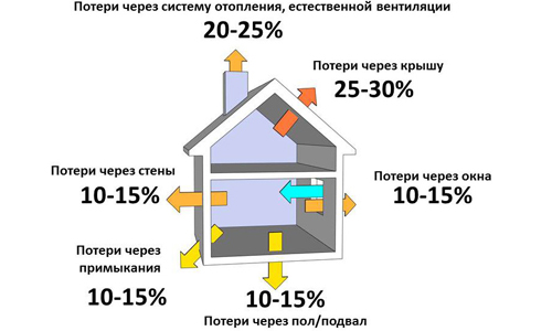
To get a more or less accurate result, it is necessary to perform calculations according to all the rules, a simplified method (100 W of heat per 1 m2 of area) will not work here. The total loss of heat by the building during the cold season consists of 2 parts:
- heat loss through enclosing structures;
- energy losses used to heat the ventilation air.
The basic formula for calculating the heat energy consumption through outdoor fences is as follows:
Heating - External design temperatures. Thermal properties of buildings. Heat transfer through the soil. Calculation methods. Mounting Bridges - Linear Heat Transfer Coefficient - Simplified Methods and Guidelines. Thermal bridges in buildings - Calculation of heat flux and surface temperature. Part 2. Linear thermal bridges.
Heating systems in buildings - a method for calculating the design heat load. Heating systems in buildings - Design load calculation method. These calculations are based on ambient and outside temperatures in the standard, depending on the climate in which our building is located. Purmo describes this topic very well.
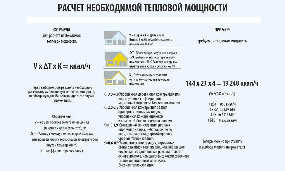
Q \u003d 1 / R x (t in - t n) x S x (1+ ∑β). Here:
- Q is the amount of heat lost by a structure of one type, W;
- R - thermal resistance of the construction material, m² ° С / W;
- S is the area of \u200b\u200bthe outer fence, m²;
- t in - internal air temperature, ° С;
- t n - the lowest ambient temperature, ° С;
- β - additional heat loss depending on the orientation of the building.
As much is said, it is rather cumbersome to do these calculations on a piece of paper, and in practice it is done using computer programs. Energy efficiency certificates take into account not only the need for heating for heating, but also hot water supply. And therefore it cannot be compared with the output of a heating boiler.
However, if the results are seasonal heat demand, then the question will look better. This figure is also expressed in kWh per year, but it can be divided by the so-called maximum power usage time. This is an empirical relationship between seasonal heat consumption and heat source capacity at the lowest temperatures.
The thermal resistance of the walls or roof of a building is determined based on the properties of the material from which they are made and the thickness of the structure. For this, the formula R \u003d δ / λ is used, where:
- λ - reference value of the thermal conductivity of the wall material, W / (m ° C);
- δ is the thickness of the layer of this material, m.
If the wall is built of 2 materials (for example, a brick with mineral wool insulation), then the thermal resistance is calculated for each of them, and the results are summed up. The outdoor temperature is selected both according to regulatory documents and personal observations, the indoor temperature is selected as needed. Additional heat losses are coefficients determined by the norms:
Fortunately, if you have an energy certificate, you can find seasonal heat demand - see the table below for “Annual flat energy demand”. When modernizing the heating system, for example, when replacing, it is necessary to install new heating devices for heat losses from the building. The fact is that heat losses at the design temperature are balanced by the heat output of the boiler and heater.
What does it look like? The blue arrow symbolizes the amount of energy supplied to your home in the form of natural gas or other fuel. It ends up in a box that pretends to be a central heating boiler. The boiler consumes a little heat and loses it through the chimney as waste, and the rest delivers it. And the heat that eventually enters the room comes out through the walls, roof and sides, floor and exhaust ventilation air.
- When the wall or part of the roof is turned to the north, northeast or northwest, then β \u003d 0.1.
- If the structure is facing southeast or west, β \u003d 0.05.
- β \u003d 0 when the outside railing faces south or southwest.
Calculation order
To take into account all the heat leaving the house, it is necessary to calculate the heat loss of the room, and each separately. For this, measurements are taken of all fences adjacent to the environment: walls, windows, roofs, floors and doors.
Simple diagram of heat loss in a building. An accurate calculation of the heat loss from a building is possible, even by appropriate standards. Taking into account the parameters of the building walls, ventilation, air infiltration, etc. You can calculate both heat loss and seasonal heat demand. As a person who is comfortable, he can download a computer program for this purpose. You can also pay someone to do this, many people provide this type of service.
Electric heater and power meter
A rough estimate of these heat losses is possible in at least several ways. For individual rooms, the easiest way to measure heat loss is with an electric heater. The challenge is to heat the room for the whole day with just this electric heater and to measure the electricity consumption.
An important point: measurements should be made on the outside, capturing the corners of the structure, otherwise the calculation of the heat loss of the house will give an underestimated heat consumption.
Windows and doors are measured by the opening they fill.
Based on the results of measurements, the area of \u200b\u200beach structure is calculated and substituted into the first formula (S, m²). The value of R obtained by dividing the thickness of the fence by the coefficient of thermal conductivity is also inserted there. building material... In the case of new windows made of metal-plastic, the R value will be advised by the representative of the installer.
If we take into account the average air temperature for a given day, we can calculate the heat consumption in a given room for the calculated temperature. After a few days, we calculated the heat loss from the entire building. It is important that you use the room normally during this experiment. The electrical heater should be located where the permanent heater is located.
Any other heat source and fuel consumption meter
This is a less accurate measurement because it takes into account the energy consumption of the boiler, rather than the amount of energy brought home and lost in the environment. At the same time, this method gives the result for the whole building faster, although it requires a little more computation.
As an example, it is worth calculating the heat loss through the enclosing walls made of bricks 25 cm thick, with an area of \u200b\u200b5 m² at an ambient temperature of -25 ° C. It is assumed that the temperature inside will be + 20 ° С, and the plane of the structure is facing north (β \u003d 0.1). First you need to take from the reference literature the thermal conductivity of the brick (λ), it is equal to 0.44 W / (m ° C). Then the heat transfer resistance is calculated using the second formula brick wall 0.25 m:
In this version, we read the fuel consumption for one day of heating the house. By multiplying the fuel consumption by its heating value, we obtain the amount of energy supplied to the boiler. If we multiply this by the efficiency of the boiler, we get the amount of energy supplied to the central heating system.
That's why we partner with market leaders. The products listed above are supplied as standard system components. These system components are offered in many variations. This structure of the system makes it more flexible than sandwich panels to customize the appearance and coating parameters to suit individual needs. Products can be delivered directly to the investment site in accordance with a previously agreed delivery schedule.
R \u003d 0.25 / 0.44 \u003d 0.57 m2 ° C / W
To determine the heat loss of a room with this wall, all the initial data must be substituted into the first formula:
Q \u003d 1 / 0.57 x (20 - (-25)) x 5 x (1 + 0.1) \u003d 434 W \u003d 4.3 kW
If the room has a window, then after calculating its area, the heat loss through the translucent opening should be determined in the same way. The same steps are repeated for floors, roof and front door. At the end, all the results are summed up, after which you can move on to the next room.
Wall cassettes are used as a special insulating material - mineral wool with improved thermal and sound insulation properties and an anti-repellent structure. The outer cover is any trapezoidal sheet profile. We supply a set of special fasteners and sealing strips.
This solves the problems of traditional wool insulation methods.
- Reduced thermal bridging and therefore more effective thermal protection.
- Improved acoustic insulation.
- Optimal use of space for isolation.
- The use of two-layer mineral wool prevents it from settling.
Heat metering for air heating
When calculating the heat loss of a building, it is important to take into account the amount of heat energy consumed by the heating system to heat the ventilation air. The share of this energy reaches 30% of the total losses, so it is unacceptable to ignore it. You can calculate the ventilation heat loss at home through the heat capacity of the air using the popular formula from the physics course:
Q air \u003d cm (t in - t n). In it:
- Q air - heat consumed by the heating system to warm up the supply air, W;
- t in and t n - the same as in the first formula, ° С;
- m is the mass flow rate of air entering the house from the outside, kg;
- с - heat capacity of the air mixture, equal to 0.28 W / (kg ° C).
Here, all values \u200b\u200bare known, except for the mass air flow rate for ventilation of premises. In order not to complicate the task for yourself, it is worth agreeing with the condition that the air environment is renewed throughout the house once an hour. Then the volumetric air flow can be easily calculated by adding up the volumes of all rooms, and then you need to convert it to mass through density. Since the density of the air mixture changes depending on its temperature, you need to take a suitable value from the table:
m \u003d 500 x 1.422 \u003d 711 kg / h
Heating such a mass of air by 45 ° C will require such an amount of heat:
Q air \u003d 0.28 x 711 x 45 \u003d 8957 W, which is approximately equal to 9 kW.
At the end of the calculations, the results of heat losses through the external enclosures are summed up with ventilation heat losses, which gives the total heat load on the building heating system.
The presented calculation methods can be simplified if the formulas are entered into Excel in the form of tables with data, this will significantly speed up the calculation.


