STEEL WATER AND GAS PIPES
TECHNICAL CONDITIONS
GOST 3262-75
PUBLISHING STANDARDS
Moscow
STATE STANDARD OF THE UNION OF SSR
dateintroduction 01.01.77
This standard applies to non-galvanized and galvanized steel welded pipes with threaded or knurled cylindrical threads and without threads, used for water and gas pipelines, heating systems, as well as for parts of water supply and gas pipelines.
1. VARIETY
1.1. Pipes are made according to the dimensions and weight given in table. one.
At the request of the consumer, pipes of a light series intended for thread rolling are manufactured according to the dimensions and weight given in table. 2.
(Modified edition, Amendment No. 1 , 3 ).
1.2. The length of the pipe is made from 4 to 12 m:
measured or multiple measured lengths with an allowance for each cut of 5 mm and a maximum deviation for the entire length plus 10 mm;
unmeasured length.
By agreement between the manufacturer and the consumer, up to 5% of pipes with a length of 1.5 to 4 m are allowed in a batch of off-gauge pipes.
Table 1
Dimensions, mm
|
Conditional pass |
Outside diameter |
Pipe wall thickness |
Weight of 1 m pipes, kg |
||||
|
ordinary |
reinforced |
ordinary |
reinforced |
||||
table 2
Dimensions, mm
|
Conditional pass |
Outside diameter |
Wall thickness |
Weight of 1 m pipes, kg |
Notes:
1. For a thread made by the knurling method, on a pipe it is allowed to reduce its inner diameter up to 10% along the entire length of the thread.
2. The mass of 1 m of pipes is calculated at a density of steel equal to 7.85 g / cm 3. Galvanized pipes are heavier than non-galvanized ones by 3%.
1.3. Limit deviations in pipe dimensions should not exceed those indicated in table. 3.
Table 3
|
Pipe dimensions |
Limit deviations for pipes manufacturing accuracy |
|
|
increased |
||
|
Outside diameter with nominal bore: |
||
|
up to 40 mm incl. |
||
|
- 0,5 |
||
|
Outside diameter with nominal bore: over 40 mm |
||
|
- 1,0 |
||
|
Wall thickness |
- 15 % |
- 10 % |
Notes:
1. The maximum deviation to the plus side in the wall thickness is limited by the maximum deviations in the mass of the pipes.
2. Pipes of normal manufacturing accuracy are used for water pipelines, gas pipelines and heating systems. Pipes of increased manufacturing accuracy are used for parts of water and gas supply structures.
1.4. Maximum deviations in pipe weight should not exceed +8%.
At the request of the consumer, the maximum deviations in weight should not exceed:
7.5% - for the party;
10% - for a separate pipe.
(Modified edition, Amendments No. 2, 5).
1.5. The curvature of pipes for 1 m of length should not exceed:
2 mm - with nominal bore up to 20 mm inclusive;
1.5 mm - with a nominal bore over 20 mm.
1.6. The pipe threads can be long or short. The requirements for the thread must correspond to those indicated in table. 4.
2.2. At the request of the consumer, the ends of pipes to be welded with a wall thickness of 5 mm or more must be chamfered at an angle of 35-40 ° to the end of the pipe. In this case, an end ring with a width of 1 - 3 mm should be left.
At the request of the consumer, on ordinary and reinforced pipes with a nominal bore of more than 10 mm, the thread is applied to both ends of the pipe.
2.1; 2.2. (Modified edition, Amendments No. 3, 4).
2.3. At the request of the consumer, pipes are equipped with couplings made in accordance with GOST 8944, GOST 8954, GOST 8965 and GOST 8966 at the rate of one coupling for each pipe.
(Modified edition, Amendment No. 3).
2.4. Cracks, captivity, swelling and sunsets are not allowed on the pipe surface.
No delamination is allowed on the pipe ends.
Separate dents, ripples, risks, traces of stripping and other defects caused by the production method are allowed, if they do not remove the wall thickness beyond the minimum dimensions, as well as a layer of scale that does not interfere with inspection.
On pipes made by furnace welding, it is allowed to reduce the outer diameter to 0.5 mm at the seam if there is a shallow thickening in this place of not more than 1.0 mm along the inner diameter.
(Modified edition, Amendments No. 3, 4).
2.5. At the request of the consumer, on pipes with a nominal bore of 20 mm or more, on the inner surface of the pipe seam, the burr must be cut or flattened, while the height of the burr or its traces should not exceed 0.5 mm.
At the request of the consumer, on pipes with a nominal bore of more than 15 mm, made by furnace welding and by the method of hot reduction, a gentle thickening with a height of no more than 0.5 mm is allowed on the inner surface of the pipes in the seam zone.
(Modified edition, Amendments No. 2, 3, 4, 5, 6).
2.6. Pipe ends must be cut at right angles. The size of the bevel of the end is allowed no more than 2 ° ... Burr residues should not exceed 0.5 mm. When removing burrs, the formation of bluntness (rounding) of the ends is allowed. Cutting of pipes in the mill line is allowed.
By agreement between the manufacturer and the consumer, burrs up to 1 mm are allowed on pipes with a nominal bore of 6-25 mm, made by furnace welding.
(Modified edition, Amendments No. 4, 6).
2.7. Galvanized pipes must have a continuous zinc coating over the entire surface with a thickness of at least 30 microns. The absence of zinc coating on the ends and threads of the pipes is allowed.
On the surface of galvanized pipes, blistering and foreign inclusions (hard zinc, oxides, sintered charge), peeling of the coating from the base metal are not allowed.
Separate flux spots and traces of pipe gripping by lifting devices, roughness and slight local influx of zinc are allowed.
It is allowed to correct individual non-galvanized sections by 0.5% of the outer pipe surface in accordance with GOST 9.307.
(Modified edition, Amendments No. 3, 4).
2.8. The pipes must be able to withstand hydraulic pressure:
2.4 MPa (25 kgf / cm 2) - pipes, ordinary and light;
3.1 MPa (32 kgf / cm 2) - reinforced pipes.
At the request of the consumer, pipes must withstand a hydraulic pressure of 4.9 MPa (50 kgf / cm 2)
2.9. Pipes with a nominal bore up to 40 mm inclusive must withstand the bend test around a mandrel with a radius equal to 2.5 of the outer diameter, and with a nominal bore of 50 mm - on a mandrel with a radius equal to 3.5 of the outer diameter.
At the request of the consumer, the pipes must withstand the expansion test:
for pipes with nominal bore from 15 to 50 mm - not less than 7%;
for pipes with a nominal bore of 65 and more - at least 4%.
At the request of the consumer, the pipes must withstand the flattening test up to a distance between the flattened surfaces equal to 2/3 of the outer diameter of the pipes.
2.8, 2.9. (Modified edition, Amendments No. 2, 3, 5).
2.10. At the request of the consumer, the mechanical properties of pipes for parts of water and gas pipelines must comply with GOST 1050.
2.11. The pipe thread must be clean, without flaws or burrs and comply with GOST 6357, accuracy class B.
Pipes with cylindrical threads are used in assembly with seals.
2.10; 2.11. (Modified edition, Amendments No. 3, 4).
2.12. At the seam, blackness on the threads is allowed if the reduction in the normal height of the thread profile does not exceed 15%, and at the request of the consumer does not exceed 10%.
Threads with stripped (for cut) or incomplete (for rolled) threads are allowed on the thread, provided that their total length does not exceed 10% of the required thread length, and at the request of the consumer does not exceed 5%.
2.13. It is allowed on the thread to reduce the useful thread length (without runaway) up to 15% compared to that specified in, and at the request of the consumer up to 10%.
2.12., 2.13. (Modified edition, Amendments No. 2, 3, 5).
2.14. Threading of galvanized pipes is carried out after galvanizing.
2.15. (Deleted, Amendment No. 3).
2.16. At the request of the consumer, pipe welds are subjected to non-destructive testing.
(Modified edition, Amendment No. 5).
3. RULES OF ACCEPTANCE
3.1. Pipes are accepted in batches. A batch must consist of pipes of the same size, of the same grade and be accompanied by one quality document in accordance with GOST 10692 with an addition for pipes intended for the manufacture of parts of water supply and gas pipelines, made of steel according to GOST 1050: chemical composition and mechanical properties of steel in accordance with the quality document of the manufacturer of the billet.
The mass of the batch is not more than 60 tons.
(Modified edition, Amendments No. 3, 4).
3.2. The surface, dimensions and curvature are checked for each pipe in the batch.
It is allowed to apply statistical control methods according to GOST 18242 with a normal level. Control plans are established by agreement between the manufacturer and the consumer.
Control of the outer diameter of pipes is carried out at a distance of at least 15 mm from the end of the pipe.
(Modified edition, Amendments No. 3, 4, 5).
3.3. To control the parameters of the thread, for testing for expansion, flattening, bending, the height of the inner burr, the remnants of burrs, the right angle and the bevel angle (for pipes with beveled edges), mechanical properties, take no more than 1%, but not less than two pipes from the batch, and for pipes made by continuous furnace welding, two pipes per batch.
(Modified edition, Amendments No. 3, 4).
3.4. All pipes are subject to weight control.
(Modified edition, Amendment No. 3).
3.5. Each pipe is subjected to a hydraulic pressure test. With 100% quality control weld non-destructive testing by hydraulic pressure is not allowed. At the same time, the ability of the pipes to withstand the test hydraulic pressure is guaranteed.
(Modified edition, Amendment No. 6).
3.6. To check the thickness of the zinc coating on the outer surface and in accessible places on the inner surface, two pipes are taken from the batch.
(Modified edition, Amendment No. 2).
3.7. Upon receipt of unsatisfactory test results for at least one of the indicators, a second test is carried out on a double sample.
Retest results apply to the entire batch.
4. TEST METHODS
4.1. For quality control, one sample is cut from each selected pipe for each type of test.
The tensile test is carried out in accordance with GOST 10006. Instead of tensile testing, it is allowed to carry out control of mechanical properties by non-destructive methods.
(Modified edition, Amendments No. 3, 6).
4.2. Inspection of the pipe surface is carried out visually.
4.3. The hydraulic test is carried out in accordance with GOST 3845 with holding under test pressure for at least 5 s.
4.4. The bend test is carried out in accordance with GOST 3728. Galvanized pipes are tested prior to coating.
(Modified edition, Amendment No. 3).
4.4a. The extension test is carried out in accordance with GOST 8694 on a tapered mandrel with a taper angle of 6 ° .
It is allowed to test on a mandrel with a taper angle of 30 ° .
(Modified edition, Amendments No. 3, 4).
4.4b. The flattening test is carried out according to GOST 8695.
(Modified edition, Amendment No. 3).
4.4c. The control of the welded seam is carried out by non-destructive methods according to the normative and technical documentation.
(Introduced additionally, Amendment No. 3).
4.5. The thickness of the zinc coating on the outer surface and in accessible places of the inner surface is controlled in accordance with GOST 9.301 and GOST 9.302, as well as with devices of the MT-41NTs, MTZON type or the "Impulse" type according to the normative and technical documentation.
4.6. The thread is checked with threaded ring gauges in accordance with GOST 2533 (third class of accuracy).
In this case, the screw-in capacity of the no-go ring gauge on the thread should be no more than three turns.
(Modified edition, Amendments No. 3, 4).
4.7. The curvature of the pipes is controlled with a straight edge according to GOST 8026 and a set of probes according to ND.
(Modified edition, Amendments No. 3, 5).
4.8. The right angle of the ends of the pipes is controlled with a square 90 ° size 160
´ 100 mm class 3 GOST 3749, plate probes set 4 according to ND or goniometer(Modified edition, Amendments No. 3, 4, 5, 6).
4.10. Weld control is carried out by non-destructive methods according to technical documentation.
(Introduced additionally, Amendment No. 4).
5. LABELING, PACKAGING, TRANSPORTATION AND STORAGE
5.1. Marking, packaging, transportation and storage are carried out in accordance with GOST 10692 with the addition.
5.1.1. The pipe thread must be protected from mechanical damage and corrosion with a lubricant according to the normative and technical documentation.
Sec. 5. (Modified edition, Amendment No. 3).
INFORMATION DATA
1. DEVELOPED AND INTRODUCED by the Ministry of Ferrous Metallurgy of the USSR 4.4
7. Reprinted with Amendments No. 1, 2, 3, 4, 5, 6, approved in November 1977, December 1978, January 1987, May 1988, November 1989, November 1991 ( IUS 1-78, 2-79, 4-87, 8-88, 2-90, 2-92)
In the MirMet company you can always purchase water and gas pipes at affordable prices. We sell products from carbon steel of various grades and offer water and gas pipes of increased accuracy and normal accuracy of various diameters and types. The range of products is wide enough and on our website you can buy pipes of measured, unmeasured and multiple measured lengths.
To order, you need to contact our managers at the specified phone numbers or independently through the online system.
Why do they order water and gas pipes from us?
Affordable prices
The price is based on the complexity and scope of work. System of discounts and bonuses for regular customers
High quality
You can be sure of us!
We have been successfully operating in the rolled metal market since 2007

Short time
The production facilities of the company allow us to fulfill orders in the shortest possible time and without delays
Where to buy in Moscow
It is easy to place an online order on our website or choose a feedback method. All the information you need is presented on our website. If you have any questions about rolled metal products, you can contact our managers. Delivery is carried out not only in Moscow and the Moscow region, we deliver products by special equipment to any region of Russia. You can pick up the order yourself at the address: Moscow region, Lyubertsy district, pos. Tomilino, st. Gogol 39/1, warehouse "Lazur". We are waiting for you!
Prices for water and gas pipes
| Item No. | Name and characteristics | Price | Unit rev. |
|---|---|---|---|
| 1 | Pipe VGP 15x2.8 | 36490.00 | RUB / ton |
| 2 | Pipe VGP 15x2.8 | 36490.00 | RUB / ton |
| 3 | Pipe VGP 20x2.8 | 34490.00 | RUB / ton |
| 4 | Pipe VGP 20x2.8 | 34490.00 | RUB / ton |
| 5 | Pipe VGP 25х3.2 | 34490.00 | RUB / ton |
| 6 | Pipe VGP 25х3.2 | 34490.00 | RUB / ton |
| 7 | Pipe VGP 100х4.5 | 34650.00 | RUB / ton |
| 8 | Pipe VGP 32х3.2 | 34690.00 | RUB / ton |
| 9 | Pipe VGP 80х4.0 | 34990.00 | RUB / ton |
| 10 | Pipe VGP 40х3.5 | 32890.00 | RUB / ton |
| 11 | Pipe VGP 65х4 | 34690.00 | RUB / ton |
| 12 | Pipe VGP 50х3.5 | 33990.00 | RUB / ton |
| 13 | VGP pipe 15x2.5 | Negotiable | RUB / ton |
| 14 | Pipe VGP 20x2.5 | Negotiable | RUB / ton |
| 15 | Pipe VGP 25x2.8 | Negotiable | RUB / ton |
| 16 | VGP pipe 32x2.5 | Negotiable | RUB / ton |
| Nominal bore, mm | Outside diameter, mm | Diameter, inch | Pipe wall thickness, mm | Weight per meter of pipes, kg | Meters per ton |
|---|---|---|---|---|---|
| 6 | 10,2 | 1/4 | 2,0 | 0,4 | 2500,0 |
| 15 | 21,3 | 1/2 | 2,8 | 1,28 | 781,3 |
| 20 | 26,8 | 3/4 | 2,8 | 1,66 | 602,4 |
| 25 | 33,5 | 1 | 3,2 | 2,39 | 418,4 |
| 32 | 42,3 | 11/4 | 3,2 | 3,09 | 323,6 |
| 40 | 48,0 | 11/2 | 3,5 | 3,84 | 260,4 |
Why buy
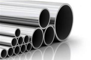
During construction, a water and gas pipe is an irreplaceable element. Not a single household, household or agricultural, can do without water supply; it is also necessary in production. Steel products can be used indoors and outdoors, unlike pipes made of other materials.
Our company is pleased to offer all the variety of water and gas pipes from the best manufacturing plants at the best prices. Product quality is guaranteed by international technical standards. By purchasing from us, you can be sure that any type of steel product has the required characteristics and will reliably serve the entire planned period.
Scope of application
A steel water-gas pipe is operated in completely different conditions, therefore, increased requirements are imposed on the quality of the welded seam at the last stage of its manufacture. The welded joint is X-ray checked.
The substances transported through the water and gas pipe have different chemical activity. Pipes of ordinary precision are used in heating systems, water and gas pipelines for domestic use. For pipes with increased accuracy, the outer diameter and wall thickness are normalized with permissible deviations. Such products are used to manufacture parts for global water and gas supply systems.
Due to such indicators as strength, maximum permissible internal pressure, thermal conductivity and tightness, water and gas pipes are used for the installation of heating systems, for the organization of gas and water supply in industrial buildings, educational institutions, office buildings, shopping complexes, residential apartment buildings and private houses.
Advantages of water and gas pipes
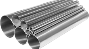
The water and gas pipe can be used in open areas, as it is made of steel and has all the advantages of this material. Also, the pipe has:
- gas impermeability;
- high strength;
- long service life (over 50 years);
- low expansion ratio.
Pipes do not deform from impact high temperaturesthat could affect pipes made of polymer material, withstand the pipes and freezing of the transported liquid.
Moreover, the product has a very affordable cost. Steel products can be galvanized, not galvanized, threaded or manufactured without it. Due to the variety of assortments and their strength characteristics, pipes are used in very many spheres of life.
Diameter is an important parameter of pipes made of metal alloys.
The classification of products by this characteristic will make it possible to calculate the project for the transportation of a specific substance through a pipeline.
When solving the set tasks, the pipe wall thickness is used along with the diameter.
Metrological standards
Standardization of the parameters of steel products will facilitate the work of designers in choosing the models that will be used in the assembly of the pipeline.
Before discussing the diameters of VGP pipes () for a specific pipeline, it is necessary to understand the characteristics of the dimensions.
The abbreviation for VGP means water and gas.
Pipes with this marking are used when laying water or gas pipelines.
Modern production offers a wide range of products that are made from different materials.
Under these conditions, the specialized pipe is in high demand among builders and operators.
GOST determines not only the diameters of pipe products, but also the corresponding dimensions of the walls. The required parameters are determined by TU and GOST.
Types of diameters
In the work on projects, the following diameter characteristics are used steel pipesproducts:
The main dimensional parameter the inner pipe diameter () is considered.
This characteristic applies not only to pipes, but also to fittings.
Along with the diameter, an accompanying value is used - the thickness of the walls of the products.
During construction, a large assortment of steel products and analogues made of polymeric materials are used.
This was the reason for the development of specialized regulatory documents - tables of steel pipe diameters.
 The measures taken help to determine the conformity of steel pipes with polymer products.
Such tables will allow you to choose the best option for rolled metal products for creating pipelines for various purposes.
That, ultimately, greatly facilitates the work of specialists and workers involved in the development of projects and the construction of trunk lines.
Measurement systems
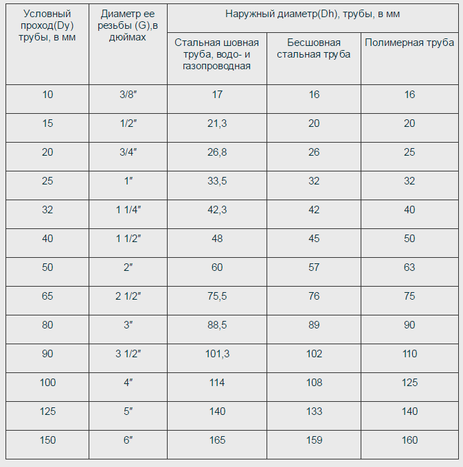
The table shows the pipe size different types... Data shown is in millimeters and inches.
Steel pipes are not losing ground and are still the main material for laying gas and water highways.
The work uses the pipe diameters indicated in inches. With this approach, there are no difficulties during the installation of the pipeline.
What do you know about? Which ones are installed on the wall and which ones are on the floor under the tiles, it is written in a useful article.
The heating scheme with a solid fuel boiler and a heat accumulator has been published.
In such cases, steel pipe size tables come to the aid of designers.
The standard shows the exact metric size steel products and compliance with polymer pipes.
The standard range of diameters used in most countries (mm): 6, 10, 15, 20, 25, 32, 40, 50, 65, 80, 100, 110, 125, 200 and so on.
Dimensions in inches are also used when designing. When translating, take into account that one inch is 2.54 centimeters.
For the installation of pipelines of residential buildings using steel products, pipes with internal diameters of 15, 20 or 32 millimeters are taken (read about GOSTs for ball, brass, coupling valves).
Large products are used when laying sewer mains (the depth of laying a pipe in a private house is indicated on the page).
Manufacturing technology of tubular products
In the production of VGP pipes, carbon alloys are used.
Carbon steel manufacturing technology consists of three stages:
- strip preparation with the required characteristics of thickness and width;
- forming a product from a strip on special equipment;
- seam creation using electric welding.
Parameters that correspond to welded steel products of certain sections, spelled out in the provisions of GOST 3262-75.
Tubular products used in gas pipelines, water pipelines for various purposes are under severe stress.
The operating time depends on the conditions and the working medium. This places increased demands on the quality of welded seams.
The welding connection must be checked by X-ray inspection.
Section calculation method
The exact dimensions of the pipes help to make a preliminary calculation of the transported volumes of the working substance.
This, in turn, will allow predicting the load on the structure.
In production, specialists are engaged in the necessary calculations.
Private house or apartment make requirements in which it is important to know the features of certain pipe products.
When repairing or installing heating of your own house, the diameter of the products is calculated in such a way that the resulting structure works with maximum heat transfer in winter.
Dimensions of steel products, polymers or reinforced versions are calculated independently. This can be done without using special tables.
The diameter of pipe products that will be used for installation, for example, a storage tank for reverse osmosis (the operating principle is described), heating, are determined by the formula:
D \u003d sqrt ((314 * Q) / (V * DT))where:
- D is the diameter of the inner lumen;
- Q is the power of the heat flow, kW;
- V - water speed, m / s;
- sqrt - square root;
- DT is the temperature difference between the inlet and outlet.
Using special tables will optimize design work, simplify the selection of products with the required parameters. This approach will save labor and financial costs.
While watching the video, you will learn about the dimensions of steel pipes and the sphere in which they are used.
UDC 669.14-462: 006.354 Group B62
STEEL WATER AND GAS PIPES
TECHNICAL CONDITIONS
GOST 3262-75
PUBLISHING STANDARDS
STATE STANDARD OF THE UNION OF SSR
STEEL WATER AND GAS PIPES
Specifications 3262-75
Water-supply and gas-supply steel pipes
Technical conditions
OKP 138500, OKP 138501
Date of introduction 01.01.77
This standard applies to non-galvanized and galvanized steel welded pipes with threaded or rolled cylindrical threads and without threads used for water and gas pipelines, heating systems, as well as for parts of plumbing and gas pipelines.
1. VARIETY
1.1. Pipes are made according to the dimensions and weight given in table. one.
At the request of the consumer, pipes of a light series intended for thread rolling are manufactured according to the dimensions and weight given in table. 2.
1.2. The length of the pipe is made from 4 to 12 m:
a) measured or multiple measured lengths with an allowance for each cut of 5 mm and a maximum deviation for the entire length plus 10 mm;
b) unmeasured length.
By agreement between the manufacturer and the consumer, up to 5% of pipes with a length of 1.5 to 4 m are allowed in a batch of off-gauge pipes.
Table 1
Conditional pass | Outside diameter | Pipe wall thickness | Weight of 1 m pipes, kg |
||||
lungs | ordinary | reinforced | lungs | ordinary | reinforced |
||
10,2 | 1,8 | 2,0 | 2,5 | 0,37 | 0,40 | 0,47 |
|
13,5 | 2,0 | 2,2 | 2,8 | 0,57 | 0,61 | 0,74 |
|
10 | 17,0 | 2,0 | 2,2 | 2,8 | 0,74 | 0,80 | 0,98 |
15 | 21,3 | 2,35 | 1,10 | ||||
15 | 21,3 | 2,5 | 2,8 | 3,2 | 1,16 | 1,28 | 1,43 |
20 | 26,8 | 2,35 | 1,42 | ||||
20 | 26,8 | 2,5 | 2,8 | 3,2 | 1,5 | 1,66 | 1,86 |
25 | 33,5 | 2,8 | 3,2 | 4,0 | 2,12 | 2,39 | 2,91 |
32 | 42,3 | 2,8 | 3,2 | 4,0 | 2,73 | 3,09 | 3,78 |
40 | 48,0 | 3,0 | 3,5 | 4,0 | 3,33 | 3,84 | 4,34 |
50 | 60,0 | 3,0 | 3,5 | 4,5 | 4,22 | 4,88 | 6,16 |
65 | 75,5 | 3,2 | 4,0 | 4,5 | 5,71 | 7,05 | 7,88 |
80 | 88,5 | 3,5 | 4,0 | 4,5 | 7,34 | 8,34 | 9,32 |
90 | 101,3 | 3,5 | 4,0 | 4,5 | 8,44 | 9,60 | 10,74 |
100 | 114,0 | 4,0 | 4,5 | 5,0 | 10,85 | 12,15 | 13,44 |
125 | 140,0 | 4,0 | 4,5 | 5,5 | 13,42 | 15,04 | 18,24 |
150 | 165,0 | 4,0 | 4,5 | 5,5 | 15,88 | 17,81 | 21,63 |
table 2
Conditional pass | Outside diameter | Wall thickness | Weight of 1 m pipes, kg |
10 | 16 | 2,0 | 0,69 |
15 | 20 | 2,5 | 1,08 |
20 | 26 | 2,5 | 1,45 |
25 | 32 | 2,8 | 2,02 |
32 | 41 | 2,8 | 2,64 |
40 | 47 | 3,0 | 3,26 |
50 | 59 | 3,0 | 4,14 |
65 | 74 | 3,2 | 5,59 |
Notes:
1. For a thread made by the knurling method, on a pipe it is allowed to reduce its inner diameter up to 10% along the entire length of the thread.
2. The mass of 1 m of pipes is calculated at a density of steel equal to 7.85 g / cm 3. Galvanized pipes are heavier than non-galvanized ones by 3%.
(Modified edition, Amendments No. 1, 3)
1.3. Limit deviations in pipe dimensions should not exceed those indicated in table. 3.
Table 3
Pipe dimensions | Limit deviations for pipes manufacturing accuracy |
|
ordinary | increased |
|
Outside diameter with nominal bore: | ||
up to 40 mm incl. | 0.4 mm | 0.4 mm |
0.5 mm | 0.4 mm |
|
Over 40 mm | 0,8 % | 0,8 % |
1,0 % | 0,8 % |
|
Wall thickness | 15 % | 10 % |
Notes:
1. The maximum deviation to the plus side in the wall thickness is limited by the maximum deviations in the mass of the pipes.
2. Pipes of normal manufacturing accuracy are used for water pipelines, gas pipelines and heating systems. Pipes of increased manufacturing accuracy are used for parts of water and gas supply structures.
1.4. Maximum deviations in pipe weight should not exceed + 8%.
At the request of the consumer, the maximum deviations in weight should not exceed:
7.5% - for the party;
10% - for a separate pipe.
(Modified edition, Amendments No. 2, 5).
1.5. The curvature of pipes for 1 m of length should not exceed:
2 mm - with nominal bore up to 20 mm inclusive;
1.5 mm - with a nominal bore over 20 mm.
1.6. The pipe threads can be long or short. The requirements for the thread must correspond to those indicated in table. 4.
Table 4
Conditional passage, mm | Thread length before running away | Conditional passage, mm | Number of threads at conditional passage | Thread length before running away |
|||
long | short | long | short |
||||
50 | 11 | 24 | 17,0 |
||||
65 | 11 | 27 | 19,5 |
||||
10 | 80 | 11 | 30 | 22,0 |
|||
15 | 14 | 14 | 9,0 | 90 | 11 | 33 | 26,0 |
20 | 14 | 16 | 10,5 | 100 | 11 | 36 | 30,0 |
25 | 11 | 18 | 11,0 | 125 | 11 | 38 | 33,0 |
32 | 11 | 20 | 13,0 | 150 | 11 | 42 | 36,0 |
40 | 11 | 22 | 15,0 | ||||
1.7. Pipes with a nominal bore of 6, 8, 10, 15 and 20 mm are wound into coils at the request of the consumer.
Legend examples
Ordinary pipe, non-galvanized, of normal manufacturing accuracy, off-gauge length, with a nominal bore of 20 mm, wall thickness of 2.8 mm, without thread and without coupling:
Pipe 20 x 2.8 GOST 3262-75
The same with the clutch:
Pipe М-20 х 2.8 GOST 3262-75
The same, measured length, with thread:
Pipe Р-20 х 2.8 - 4000 GOST 3262-75
The same, with zinc coating, unmeasured length, with thread:
Pipe Ts-R-20 x 2.8 GOST 3262-75
The same, with zinc coating, measured length, with thread:
Pipe Ts-R-20 x 2.8 - 4000 GOST 3262-75
For pipes for thread rolling, the letter H is indicated after the word "pipe" in the symbol.
For pipes with long threads, the letter D. is indicated in the symbol after the word "pipe".
For pipes of increased manufacturing accuracy, the letter P. is indicated in the symbol after the size of the conditional passage.
(Modified edition, Amendment No. 1).
2. TECHNICAL REQUIREMENTS
2.1. Pipes are manufactured in accordance with the requirements of this standard and according to the technological regulations, approved in the prescribed manner, from steels in accordance with GOST 380-88 and GOST 1050-88 without standardizing mechanical properties and chemical composition.
Pipes for parts of water supply and gas supply structures are made of steel in accordance with GOST 1050-88.
2.2. At the request of the consumer, at the ends of pipes to be welded with a wall thickness of 5 mm or more, chamfers should be made at an angle of 35-40 ° to the end of the pipe. In this case, an end ring with a width of 1 - 3 mm should be left.
At the request of the consumer, on ordinary and reinforced pipes with a nominal bore of more than 10 mm, the thread is applied to both ends of the pipe.
2.1; 2.2. (Modified edition, Amendments No. 3, 4).
2.3. At the request of the consumer, pipes are equipped with couplings made in accordance with GOST 8944-75, GOST 8954-75, GOST 8965-75 and GOST 8966-75 at the rate of one coupling for each pipe.
(Modified edition, Amendment No. 3).
2.4. Cracks, captivity, swelling and sunsets are not allowed on the pipe surface.
No delamination is allowed on the pipe ends.
Separate dents, ripples, risks, traces of stripping and other defects due to the production method are allowed, if they do not remove the wall thickness beyond minimum dimensionsand a layer of scale that does not interfere with inspection.
On pipes made by furnace welding, it is allowed to reduce the outer diameter to 0.5 mm at the seam if there is a shallow thickening in this place of not more than 1.0 mm along the inner diameter.
(Modified edition, Amendments No. 3, 4).
2.5. At the request of the consumer, on pipes with a nominal bore of 20 mm or more, the burr must be cut or flattened on the inner surface of the pipe seam, while the height of the burr or its traces should not exceed 0.5 mm.
At the request of the consumer, on pipes with a nominal bore of more than 15 mm, made by furnace welding and by the method of hot reduction, a gentle thickening with a height of no more than 0.5 mm is allowed on the inner surface of the pipes in the seam zone.
(Modified edition, Amendments No. 2, 3, 4, 5, 6).
2.6. Pipe ends must be cut at right angles. The size of the bevel of the end is allowed not more than 2 °. Burr residues should not exceed 0.5 mm. When removing burrs, the formation of bluntness (rounding) of the ends is allowed. Cutting of pipes in the mill line is allowed.
By agreement between the manufacturer and the consumer, burrs up to 1 mm are allowed on pipes with a nominal bore of 6-25 mm, made by furnace welding.
(Modified edition, Amendments No. 4, 6).
2.7. Galvanized pipes must have a continuous zinc coating over the entire surface with a thickness of at least 30 microns. The absence of zinc coating on the ends and threads of the pipes is allowed.
On the surface of galvanized pipes, blistering and foreign inclusions (hard zinc, oxides, sintered mixture), peeling of the coating from the base metal are not allowed.
Separate flux spots and traces of pipe gripping by lifting devices, roughness and slight local influx of zinc are allowed.
It is allowed to correct individual non-galvanized sections by 0.5% of the outer surface of the pipe in accordance with GOST 9.307-89.
(Modified edition, Amendments No. 3, 4).
2.8. The pipes must be able to withstand hydraulic pressure:
2.4 MPa (25 kgf / cm 2) - pipes, ordinary and light;
3.1 MPa (32 kgf / cm 2) - reinforced pipes.
At the request of the consumer, pipes must withstand a hydraulic pressure of 4.9 MPa (50 kgf / cm 2)
(Modified edition, Amendments No. 2, 3, 5).
2.9. Pipes with a nominal bore up to 40 mm inclusive must withstand the bend test around a mandrel with a radius equal to 2.5 of the outer diameter, and with a nominal bore of 50 mm - on a mandrel with a radius equal to 3.5 of the outer diameter.
At the request of the consumer, the pipes must withstand the expansion test:
for pipes with nominal bore from 15 to 50 mm - not less than 7%;
for pipes with a nominal bore of 65 and more - at least 4%.
At the request of the consumer, the pipes must withstand the flattening test up to a distance between flattened surfaces equal to 2/3 of the outer diameter of the pipes.
(Modified edition, Amendments No. 2, 3, 5).
2.10. At the request of the consumer, the mechanical properties of pipes for parts of water and gas pipelines must comply with GOST 1050-88.
2.11. The pipe thread must be clean, without flaws or burrs and comply with GOST 6357-81, accuracy class B.
Pipes with cylindrical threads are used in assembly with seals.
2.10; 2.11. (Modified edition, Amendments No. 3, 4).
2.12. At the seam, blackness on the threads is allowed if the reduction in the normal height of the thread profile does not exceed 15%, and at the request of the consumer does not exceed 10%.
Threads with stripped (for cut) or incomplete (for rolled) threads are allowed on the thread, provided that their total length does not exceed 10% of the required thread length, and at the request of the consumer does not exceed 5%.
(Modified edition, Amendments No. 2, 3, 5).
2.13. It is allowed on the thread to reduce the effective length of the thread (without runaway) up to 15% compared to that indicated in table. 4, and at the request of the consumer up to 10%.
(Modified edition, Amendments No. 2, 3, 5).
2.14. Threading of galvanized pipes is carried out after galvanizing.
2.15. (Deleted, Amendment No. 3).
2.16. At the request of the consumer, pipe welds are subjected to non-destructive testing.
(Modified edition, Amendment No. 5).
3. RULES OF ACCEPTANCE
3.1. Pipes are accepted in batches. A batch must consist of pipes of the same size, of the same brand and be accompanied by one quality document in accordance with GOST 10692-80 with an addition for pipes intended for the manufacture of parts of water supply and gas pipeline structures, made of steel in accordance with GOST 1050-88: chemical composition and mechanical properties steel in accordance with the document on the quality of the manufacturer of the billet.
The mass of the batch is not more than 60 tons.
(Modified edition, Amendments No. 3, 4).
3.2. The surface, dimensions and curvature are checked for each pipe in the batch.
It is allowed to use statistical control methods according to GOST 18242-72 with a normal level. Control plans are established by agreement between the manufacturer and the consumer.
Control of the outer diameter of pipes is carried out at a distance of at least 15 mm from the end of the pipe.
(Modified edition, Amendments No. 3, 4, 5).
3.3. To control the parameters of the thread, for testing for expansion, flattening, bending, the height of the inner burr, the remnants of burrs, the right angle and the bevel angle (for pipes with beveled edges), mechanical properties, take no more than 1%, but not less than two pipes from the batch, and for pipes made by continuous furnace welding, two pipes per batch.
(Modified edition, Amendments No. 3, 4).
3.4. All pipes are subject to weight control.
(Modified edition, Amendment No. 3).
3.5. Each pipe is subjected to a hydraulic pressure test. With 100% quality control of the weld by non-destructive methods, it is allowed not to carry out the hydraulic pressure test. At the same time, the ability of pipes to withstand the test hydraulic pressure is guaranteed.
(Modified edition, Amendment No. 6).
3.6. To check the thickness of the zinc coating on the outer surface and in accessible places on the inner surface, two pipes are taken from the batch.
(Modified edition, Amendment No. 2).
3.7. Upon receipt of unsatisfactory test results for at least one of the indicators for it, a repeated test is carried out on a doubled sample.
Retest results apply to the entire batch.
4. TEST METHODS
4.1. For quality control, one sample is cut from each selected pipe for each type of test.
The tensile test is carried out in accordance with GOST 10006-80. Instead of tensile testing, it is allowed to carry out control of mechanical properties by non-destructive methods.
4.2. Inspection of the pipe surface is carried out visually.
4.3. Hydraulic test carried out in accordance with GOST 3845-75 with holding under test pressure for at least 5 s.
4.4. The bend test is carried out in accordance with GOST 3728-78. Galvanized pipes are tested prior to coating.
(Modified edition, Amendment No. 3).
4.4a. The extension test is carried out in accordance with GOST 8694-75 on a conical mandrel with a taper angle of 6 °.
Testing on a mandrel with a taper angle of 30 ° is allowed.
(Modified edition, Amendments No. 3, 4).
4.4b. Flattening test is carried out according to GOST 8695-75.
(Modified edition, Amendment No. 3).
4.4c. The control of the welded seam is carried out by non-destructive methods according to the normative and technical documentation.
(Introduced additionally, Amendment No. 3).
4.5. The thickness of the zinc coating on the outer surface and in accessible places of the inner surface is controlled in accordance with GOST 9.301-86 and GOST 9.302-88, as well as with devices of the MT-41NTs, MTZON or Impulse type according to the regulatory and technical documentation.
4.6. The thread is checked with threaded ring gauges in accordance with GOST 2533-88 (third class of accuracy).
In this case, the screwing capacity of the no-through ring gauge on the thread should be no more than three turns.
(Modified edition, Amendments No. 3, 4).
4.7. The curvature of the pipes is controlled with a straight edge in accordance with GOST 8026-92 and a set of probes in accordance with TU 2-034-225-87.
(Modified edition, Amendments No. 3, 5).
4.8. The right angle of the pipe ends is controlled with a 90 ° square with a size of 160x100 mm of class 3 GOST 3749-77, plate probes set 4 TU 2-034-225-87 or a goniometer GOST 5378-88. The bevel angle of the chamfer is controlled by a goniometer in accordance with GOST 5378-88.
(Modified edition, Amendments No. 3, 6).
4.9. Outside diameter control is carried out with smooth micrometers according to GOST 6507-90, calibers-staples according to GOST 2216-84 or GOST 18362-73.
The wall thickness, the height of the inner burr and the height of the burrs are measured with a micrometer according to GOST 6507-90 or a wall gauge according to GOST 11358-89 from both ends of the pipe.
The length of the pipes is measured with a tape measure in accordance with GOST 7502-89. The thread is controlled with gauges according to GOST 2533-88.
The mass control of a batch of pipes is carried out on a scale of no more than 10 tons with a graduation price of no more than 20 kg.
(Modified edition, Amendments No. 3, 4, 5, 6).
4.10. Weld control is carried out by non-destructive methods according to technical documentation.
(Introduced additionally, Amendment No. 4).
5. LABELING, PACKAGING, TRANSPORTATION AND STORAGE
5.1. Marking, packaging, transportation and storage are carried out in accordance with GOST 10692-80 with the addition.
5.1.1. The pipe thread must be protected from mechanical damage and corrosion with a lubricant according to the normative and technical documentation.
Sec. 5. (Modified edition, Amendment No. 3).
INFORMATION DATA
1. DEVELOPED AND INTRODUCED by the Ministry of Ferrous Metallurgy of the USSR
DEVELOPERS
V. I. Struzhok, Cand. tech. Sciences, V. M. Vorona, Cand. tech. Sciences, Yu. M. Mironov, Cand. tech. Nuk, A.I. Postolova
2. APPROVED AND INTRODUCED INTO EFFECT by the Decree of the USSR State Committee for Standards dated 11.09.75 No. 2379
3. Inspection frequency 5 years
4. REPLACE GOST 3262-62
5. REFERENCE REGULATORY AND TECHNICAL DOCUMENTS
Item number |
|
GOST 9.301-86 | 4.5 |
GOST 9.302-88 | 4.5 |
GOST 9.307-89 | 2.7 |
GOST 380-88 | 2.1 |
GOST 1050-88 | 2.1, 2.10, 3.1 |
GOST 2216-84 | 4.9 |
GOST 2533-88 | 4.6, 4.9 |
GOST 3728-78 | 4.4 |
GOST 3749-77 | 4.8 |
GOST 3845-75 | 4.3 |
GOST 5378-88 | 4.8 |
GOST 6357-81 | 2.11 |
GOST 6507-90 | 4.9 |
GOST 7502-89 | 4.9 |
GOST 8026-92 | 4.7 |
GOST 8694-75 | 4.4a |
GOST 8695-75 | 4.4b |
GOST 8944-75 | 2.3 |
GOST 8954-75 | 2.3 |
GOST 8965-75 | 2.3 |
GOST 8966-75 | 2.3 |
GOST 10006-80 | 4.1 |
GOST 10692-80 | 3.1 |
GOST 11358-89 | 4.9 |
GOST 18242-72 | 3.2 |
GOST 18363-73 | 4.9 |
TU 2-034-225-88 | 4.7, 4.8 |
6. Reissue (May 1994) with Amendments No. 1, 2, 3, 4, 5, 6, approved in November 1977, December 1978, January 1987, May 1988, November 1989. , November 1991 (IUS 1-78, 2-79, 4-87, 8-88, 2-90, 2-92)
STEEL WATER & GAS PIPES
TECHNICAL CONDITIONS
GOST 3262-75
PUBLISHING STANDARDS
Moscow
STATE STANDARD OF THE UNION OF SSR
dateintroduction 01.01.77
This standard applies to non-galvanized and galvanized steel welded pipes with cut or rolled cylindrical threads and without threads used for water and gas pipelines, heating systems, as well as for parts of water supply and gas pipelines.
1. VARIETY
1.1. Pipes are manufactured in sizes and weights given in table. one.
At the request of the consumer, light series pipes intended for thread rolling are made according to the mass dimensions given in table. 2.
(Modified edition, Amendment No. 1 , 3 ).
1.2. The length of the pipe is made from 4 to 12 m:
measured or multiple measured length with an allowance for each cut of 5 mm and a maximum deviation for the entire length plus 10 mm;
unmeasured length.
By agreement between the manufacturer and the consumer, in a batch of off-gauge pipes, up to 5% of pipes with a length of 1.5 to 4 m are allowed.
Table 1
Dimensions, mm
| Conditional pass | Outside diameter | Pipe wall thickness | Weight of 1 m pipes, kg |
||||
| ordinary | reinforced | ordinary | reinforced |
||||
table 2
Dimensions, mm
| Conditional pass | Outside diameter | Wall thickness | Weight of 1 m pipes, kg |
Notes:
1. For a thread made by the knurling method on a pipe, it is allowed to reduce its internal diameter up to 10% along the entire length of the thread.
2. The mass of 1 m of pipes is calculated at a steel density of 7.85 g / cm 3. Galvanized pipes are heavier than non-galvanized ones by 3%.
1.3. Limit deviations in pipe sizes should not exceed those indicated in table. 3.
Table 3
| Pipe dimensions | Limit deviations for pipes manufacturing accuracy |
|
| increased |
||
| Outside diameter with nominal bore: | ||
| up to 40 mm incl. | ||
| - 0,5 |
||
| Outside diameter with nominal bore: over 40 mm | ||
| - 1,0 |
||
| Wall thickness | - 15 % | - 10 % |
Notes:
1. The maximum deviation in the plus side along the wall thickness is limited by the maximum deviations in the pipe mass.
2. Pipes of ordinary manufacturing accuracy are used for water pipelines, gas pipelines and heating systems. Pipes of increased manufacturing accuracy are used for parts of water and gas pipeline structures.
1.4. Limit deviations in pipe weight should not exceed +8%.
At the request of the consumer, the maximum deviations in weight should not exceed:
7.5% - for the party;
10% - for a separate pipe.
(Modified edition, Amendments No. 2, 5).
1.5. The curvature of pipes for 1 m length should not exceed:
2 mm - with nominal bore up to 20 mm inclusive;
1.5 mm - with nominal bore over 20 mm.
1.6. The pipe threads can be long or short. The requirements for the thread must correspond to those indicated in table. 4.
2.2. At the request of the consumer, the ends of the pipes to be welded with a wall thickness of 5 mm or more must be chamfered at an angle of 35-40 ° to the end of the pipe. In this case, an end ring with a width of 1 - 3 mm should be left.
At the request of the consumer, on ordinary and reinforced pipes with a nominal bore of more than 10 mm, threads are applied to both ends of the pipe.
2.1; 2.2. (Modified edition, Amendments No. 3, 4).
2.3. At the request of the consumer, pipes are completed with couplings made in accordance with GOST8944, GOST8954, GOST8965 and GOST8966 at the rate of one coupling for each pipe.
(Modified edition, Amendment No. 3).
2.4. Cracks, captivity, swelling and sunsets are not allowed on the pipe surface.
No delamination is allowed on the pipe ends.
Separate dents, ripples, risks, traces of stripping and other defects caused by the method of production are allowed, if they do not remove the wall thickness beyond the minimum dimensions, as well as a layer of scale that does not interfere with inspection.
On pipes made by the furnace welding method, it is allowed to reduce the outer diameter to 0.5 mm at the seam if there is a shallow thickening in this place along the inner diameter of not more than 1.0 mm.
(Modified edition, Amendments No. 3, 4).
2.5. At the request of the consumer, on pipes with a nominal bore of 20 mm or more, on the inner surface of the pipe seam, the burr must be cut or flattened, while the height of the burr or its traces should not exceed 0.5 mm.
At the request of the consumer, on pipes with a nominal bore of more than 15 mm, made by furnace welding using a hot reduction method, a gently sloping thickening with a height of no more than 0.5 mm is allowed on the inner surface of the pipes in the weld zone.
(Modified edition, Amendments No. 2, 3, 4, 5, 6).
2.6. The pipe ends must be cut at right angles. The size of the bevel of the end is allowed no more than 2 ° .The remaining burrs must not exceed 0.5 mm. When removing burrs, the formation of bluntness (rounding) of the ends is allowed. It is allowed to cut pipes in the line of Astana.
By agreement between the manufacturer and the consumer, burrs up to 1 mm are allowed on pipes with a nominal bore of 6-25 mm, made by the method of injection welding.
(Modified edition, Amendments No. 4, 6).
2.7. Galvanized pipes must have a continuous zinc coating over the entire surface with a thickness of at least 30 microns. The absence of zinc coating on the ends and threads of the pipes is allowed.
On the surface of galvanized pipes, blistering and foreign inclusions (hard zinc, oxides, sintered charge), peeling of the coating from the base metal are not allowed.
Separate flux spots and traces of pipe gripping by lifting devices, roughness and slight local influx of zinc are allowed.
It is allowed to correct individual non-galvanized sections by 0.5% of the outer surface of the pipe in accordance with GOST 9.307.
(Modified edition, Amendments No. 3, 4).
2.8. The pipes must be able to withstand hydraulic pressure:
2.4 MPa (25 kgf / cm 2) - pipes, ordinary and light;
3.1 MPa (32 kgf / cm 2) - reinforced pipes.
At the request of the consumer, the pipes must withstand a hydraulic pressure of 4.9 MPa (50 kgf / cm 2)
2.9. Pipes with a nominal bore up to 40 mm inclusive must withstand the bend test around an adapter with a radius equal to 2.5 of the outer diameter, and with a nominal bore of 50 mm, on a mandrel with a radius of 3.5 of the outer diameter.
At the request of the consumer, the pipes must withstand the dispensing test:
for pipes with nominal bore from 15 to 50 mm - not less than 7%;
for pipes with nominal bore 65 and more - not less than 4%.
At the request of the consumer, the pipes must withstand the flattening test up to a distance between the flattened surfaces equal to 2/3 of the outer diameter of the pipes.
2.8,2.9. (Modified edition, Amendments No. 2, 3, 5).
2.10. At the request of the consumer, the mechanical properties of pipes for parts of water and gas supply structures must comply with GOST 1050.
2.11. The pipe thread must be clean, without flaws and burrs and comply with GOST 6357, accuracy class B.
Tubes with cylindrical threads are used for assembly with seals.
2.10; 2.11. (Modified edition, Amendments No. 3, 4).
2.12. Black on the threads is allowed in the place where the reduction in the normal height of the thread profile does not exceed 15%, and at the request of the consumer does not exceed 10%.
Threads with stripped (for cut) or incomplete (for rolled) threads are allowed on the thread, provided that their total length does not exceed 10% of the required thread length, and at the request of the consumer does not exceed 5%.
2.13. Allowed on the thread to reduce the effective length of the thread (without runaway) up to 15% compared to that specified in, and at the request of the consumer up to 10%.
2.12.,2.13. (Modified edition, Amendments No. 2, 3, 5).
2.14. Threading on galvanized pipes is carried out after galvanizing.
2.15. (Deleted, Amendment No. 3).
2.16. At the request of the consumer, pipe welds are subjected to non-destructive testing.
(Modified edition, Amendment No. 5).
3. RULES OF ACCEPTANCE
3.1. Pipes are accepted in batches. A batch must consist of pipes of the same size, of the same grade and be accompanied by one quality document in accordance with GOST 10692 with an addition for pipes intended for the manufacture of parts of water and gas pipelines, made of steel according to GOST1050: chemical composition and mechanical properties of steel in accordance with the document on the quality of the manufacturer of the workpiece.
The mass of the batch is not more than 60 tons.
(Modified edition, Amendments No. 3, 4).
3.2. The surface, dimensions and curvature are checked for each pipe in the batch.
It is allowed to apply statistical control methods in accordance with GOST 18242 with a normal level. Control plans are established by agreement between the manufacturer and the consumer.
Control of the outer diameter of pipes is carried out at a distance of at least 15 mm from the end of the pipe.
(Modified edition, Amendments No. 3, 4, 5).
3.3. To control the parameters of the thread, for testing for expansion, flattening, bending, the height of the inner burr, the remnants of burrs, the right angle and the chamfer angle (for pipes with beveled edges), the mechanical properties are selected no more than 1%, but not less than two pipes from the batch, ad for pipes made by continuous furnace welding - two pipes from a batch.
(Modified edition, Amendments No. 3, 4).
3.4. All pipes are subject to weight control.
(Modified edition, Amendment No. 3).
3.5. Each pipe is subjected to a hydraulic pressure test. At 100% quality control of the welded seam by non-destructive methods, it is allowed not to carry out hydraulic pressure testing. At the same time, the ability of the pipes to withstand the test hydraulic pressure is guaranteed.
(Modified edition, Amendment No. 6).
3.6. To check the thickness of the zinc coating on the outer surface and in accessible places on the inner surface, two pipes are taken from the batch.
(Modified edition, Amendment No. 2).
3.7. When unsatisfactory test results are obtained for at least one of the indicators, the second test is carried out on a double sample.
Retest results apply to the entire batch.
4. TEST METHODS
4.1. For quality control, one sample is cut from each selected pipe for each type of test.
Tensile testing is carried out in accordance with GOST 10006. Instead of tensile testing, it is allowed to carry out control of mechanical properties by non-destructive methods.
(Modified edition, Amendments No. 3, 6).
4.2. Inspection of the pipe surface is carried out visually.
4.3. Hydraulic testing is carried out in accordance with GOST 3845 with holding under test pressure for at least 5 s.
4.4. The bend test is carried out in accordance with GOST 3728. Galvanized pipes are tested prior to coating.
(Modified edition, Amendment No. 3).
4.4a. The expansion test is carried out in accordance with GOST 8694 on a tapered mandrel with a taper angle of 6 ° .
It is allowed to test on a mandrel with a taper angle of 30 ° .
(Modified edition, Amendments No. 3, 4).
4.4b. The flattening test is carried out in accordance with GOST 8695.
(Modified edition, Amendment No. 3).
4.4c. The control of the welded joint is carried out by non-destructive methods according to the normative and technical documentation.
(Introduced additionally, Amendment No. 3).
4.5. The thickness of the zinc coating on the outer surface and in accessible places on the inner surface is controlled in accordance with GOST 9.301 and GOST 9.302, as well as with devices of the MT-41NTs, MTZON type or "Impulse" type of regulatory and technical documentation.
4.6. The thread is checked with threaded ring gauges in accordance with GOST 2533 (third class of accuracy).
In this case, the screwing capacity of the non-bore ring gauge onto the thread should be no more than three turns.
(Modified edition, Amendments No. 3, 4).
4.7. The curvature of the tubes is controlled with a straight edge according to GOST 8026 and a set of probes according to ND.
(Modified edition, Amendments No. 3, 5).
4.8. The right angle of the ends of the tubes is controlled with a square 90 ° size 160´ 100 mm class 3 GOST 3749, plate probes set 4 according to ND or goniometer
(Modified edition, Amendments No. 3, 4, 5, 6).
4.10. Weld control is carried out by non-destructive methods according to technical documentation.
(Introduced additionally, Amendment No. 4).
5. LABELING, PACKAGING, TRANSPORTATION AND STORAGE
5.1. Marking, packaging, transportation and storage are carried out in accordance with GOST 10692 with the addition.
5.1.1. The pipe thread must be protected from mechanical damage and corrosion by lubricating the normative and technical documentation.
Sec. 5. (Modified edition, Amendment No. 3).
INFORMATION DATA
1. DEVELOPED AND INTRODUCED by the Ministry of Ferrous Metallurgy of the USSR 4.4
7. Reissue with Amendments No. 1, 2, 3, 4, 5, 6, approved in November 1977, December 1978, January 1987, May 1988, November 1989, November 1991 (IUS 1 -78.2-79, 4-87, 8-88, 2-90, 2-92)


