Schemes of the simplest electronic devices for beginner radio amateurs. Simple electronic toys and devices that can be useful for the home. The circuits are based on transistors and do not contain scarce components. Bird voice simulators, musical instruments, LED music and others.
Nightingale trill generator
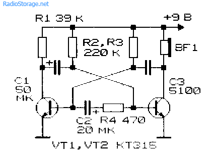
The nightingale trill generator, made on an asymmetric multivibrator, is assembled according to the circuit shown in Fig. 1. The low-frequency oscillatory circuit formed by the telephone capsule and capacitor SZ is periodically excited by pulses generated by the multivibrator. As a result, sound signals are formed that resemble nightingale trills. Unlike the previous scheme, the sound of this simulator is not controlled and, therefore, more monotonous. The sound timbre can be selected by changing the capacitance of the capacitor SZ.
Rice. 1. Generator-simulator of nightingale trills, device diagram.
Electronic copycat of the canary singing
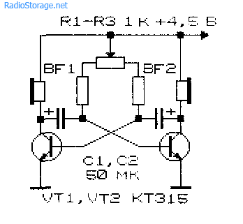
Rice. 2. Circuit diagram of an electronic canary singing imitator.
An electronic imitator of the canary's singing is described in the book by B.S. Ivanov (Fig. 2). It is also based on an asymmetric multivibrator. The main difference from the previous circuit is the RC circuit connected between the bases of the multivibrator transistors. However, this simple innovation allows you to radically change the nature of the generated sounds.
Duck quack simulator
The duck quack simulator (Fig. 3), proposed by E. Briginevich, like other simulator circuits, is implemented on an asymmetric multivibrator [R 6/88-36]. The telephone capsule BF1 is included in one arm of the multivibrator, and the LEDs HL1 and HL2 connected in series are included in the other.
Both loads work alternately: either a sound is made, or the LEDs flash - the eyes of the “duck”. The tone of the sound is selected by resistor R1. It is advisable to make the device switch based on a magnetically controlled contact, which can be homemade.
Then the toy will turn on when a disguised magnet is brought to it.

Rice. 3. Scheme of a duck quack simulator.
Rain noise generator
Rice. 4. Schematic diagram of a “rain noise” generator using transistors.
The “rain noise” generator described in the monograph by V.V. Matskevich (Fig. 4), produces sound pulses that are alternately reproduced in each of the telephone capsules. These clicks vaguely resemble raindrops falling on a windowsill.
In order to make the droplet fall random, the circuit (Fig. 4) can be improved by introducing, for example, a field-effect transistor channel in series with one of the resistors. The gate of the field-effect transistor will be an antenna, and the transistor itself will be a controlled variable resistor, the resistance of which will depend on the electric field strength near the antenna.
Electronic drum attachment
Electronic drum - a circuit that generates a sound signal of the appropriate sound when touching a sensor contact (Fig. 5) [MK 4/82-7]. The operating frequency of generation is in the range of 50...400 Hz and is determined by the parameters of the RC elements of the device. Such generators can be used to create a simple electric musical instrument with touch control.

Rice. 5. Schematic diagram of an electronic drum.
Electronic violin with touch controls

Rice. 6. Circuit of an electronic violin using transistors.
A sensor-type electronic “violin” is represented by a circuit given in the book by B.S. Ivanov (Fig. 6). If you put your finger on the touch contacts of the “violin”, the pulse generator, made on transistors VT1 and VT2, is turned on. A sound will be heard in the telephone capsule, the height of which is determined by the electrical resistance of the area of the finger applied to the touch plates.
If you press your finger harder, its resistance will decrease, and the pitch of the sound will correspondingly increase. The resistance of the finger also depends on its humidity. By changing the degree of pressing of your finger to the contacts, you can play a simple melody. The initial frequency of the generator is set with potentiometer R2.
Electric musical instrument

Rice. 7. Diagram of a simple homemade electric musical instrument.
Electric musical instrument based on a multivibrator [V.V. Matskevich] produces rectangular electrical pulses, the frequency of which depends on the resistance value Ra - Rn (Fig. 7). Using such a generator, you can synthesize a sound scale within one or two octaves.
The sound of rectangular signals is very reminiscent of organ music. Based on this device, a music box or organ can be created. To do this, contacts of various lengths are applied around the circumference of a disk rotated by a handle or an electric motor.
Pre-selected resistors Ra - Rn are soldered to these contacts, which determine the pulse frequency. The length of the contact strip determines the duration of the sound of a particular note when the common movable contact slides.
Simple color music using LEDs
A color and musical accompaniment device with multi-colored LEDs, the so-called “flasher,” will decorate the musical sound with an additional effect (Fig. 8).
The input audio signal is divided by simple frequency filters into three channels, conventionally called low-frequency (red LED); mid-frequency (green LED) and high-frequency (yellow LED).
The high-frequency component is isolated by the chain C1 and R2. The “mid-frequency” component of the signal is isolated by a sequential type LC filter (L1, C2). As a filter inductor, you can use an old universal head from a tape recorder, or the winding of a small transformer or inductor.
In any case, when setting up the device, you will need to individually select the capacitance of capacitors C1 - S3. The low-frequency component of the sound signal passes freely through circuit R4, NW to the base of transistor VT3, which controls the glow of the “red” LED. “High” frequency currents are short-circuited by the capacitor SZ, because it has extremely little resistance to them.

Rice. 8. Simple color and music installation using transistors and LEDs.
LED electronic "guess the color" toy
The electronic machine is designed to guess the color of the LED that turns on (Fig. 9) [B.S. Ivanov]. The device contains a pulse generator - a multivibrator on transistors VT1 and VT2, connected to a trigger on transistors VT3, VT4. A trigger, or a device with two stable states, alternately switches after each of the pulses that arrive at its input.
Accordingly, the multi-colored LEDs included in each of the trigger arms as a load are illuminated in turn. Since the generation frequency is quite high, the blinking of the LEDs when the pulse generator is turned on (by pressing the SB1 button) merges into a continuous glow. If you release the SB1 button, generation stops. The trigger is set to one of two possible stable states.
Since the switching frequency of the trigger was quite high, it was impossible to predict in advance what state the trigger would be in. Although there are exceptions to every rule. Players are asked to determine (predict) which color will appear after the next launch of the generator.
Or you can guess what color will light up after releasing the button. With a large set of statistics, the probability of equilibrium, equally probable illumination of LEDs should approach the value of 50:50. For a small number of attempts, this relationship may not hold.

Rice. 9. Schematic diagram of an electronic toy using LEDs.
Electronic toy "who has the best reaction"
An electronic device that allows you to compare the reaction speed of two subjects [B.S. Ivanov], can be assembled according to the diagram shown in Fig. 10. The indicator that lights up first is the LED of the one who presses “their” button first.
The device is based on a trigger using transistors VT1 and VT2. To re-test the reaction speed, the power of the device should be briefly turned off with an additional button.

Rice. 10. Schematic diagram of the “who has the best reaction” toy.
Homemade photo gallery

Rice. 11. Schematic diagram of the photo gallery.
S. Gordeev's lighting system (Fig. 11) allows you not only to play, but also to train [R 6/83-36]. A photocell (photoresistor, photodiode - R3) is aimed at a luminous point or a sunbeam and the trigger (SA1) is pressed. Capacitor C1 is discharged through a photocell to the input of a pulse generator operating in standby mode. There is a sound in the telephone capsule.
If the pickup is inaccurate and the resistance of resistor R3 is high, then the discharge energy is not enough to start the generator. A lens is needed to focus light.
Literature: Shustov M.A. Practical circuit design (Book 1), 2003.
Currently, a large number of electrical musical instruments of various design and sound are known. A wide circle of radio amateurs and musicians are well aware of some of them, while others are known only to a limited circle of specialists. There are the simplest instruments, assembled on just one transistor, but there are also those that, in terms of the complexity of their design, can compete with electronic computers. In this paragraph we will consider only relatively simple electromusical instruments, designed to be repeated by beginning radio amateurs and electric musicians. Some of the instruments described are more reminiscent of transistorized toys. But one way or another, the principles on which the operation of these tools are based are fundamental for more complex and advanced tools, devices and automation.
Electronic organ based on a unijunction transistor. One of the new and promising semiconductor devices in amateur practice is the unijunction transistor. Most often, such transistors are used in various kinds of master oscillators, where the generation frequency can be changed within a very wide range by changing the resistance or capacitance in the emitter circuit. This property of generators based on unijunction transistors is used in the simplest electronic organ, the circuit diagram of which is shown in Fig. 41. Here, transistor T1 is included in a self-oscillator of electrical oscillations, the frequency of which changes when you press any of the keys A-3, which connect variable resistors R4-R11 with the emitter of unijunction transistor T1. The frequency of the generated oscillations, and therefore the tone of the sound, can be adjusted by appropriately adjusting these resistors.
"Electronic organ" according to the diagram in Fig. 41 has neither a power amplifier nor a loudspeaker needed to create sound vibrations. Therefore, it must be connected at least to the pickup sockets available in every broadcast receiver. The domestic unijunction transistor KT117 is most suitable as transistor T1.
The power source can be two 3336L batteries connected in series. The magazine of American radio amateurs, where this “electronic organ” is described, states that it can be used not only as an entertaining toy, but with great practical benefit as a multi-channel signaling device, for example an electric bell. In this case, the signals differ not in the number of rings, but in the tone of the signal, depending on the pressing of a particular key.
Electronic canary. Since ancient times, canaries have delighted nature lovers with their singing. But keeping canaries at home requires a certain skill and patience. Apparently, for these reasons, artificial canaries appeared on sale in Japan and the USA, looking very similar to real ones and emitting trills close to the singing of natural canaries. The source of this singing is miniature transistor generators of electrical vibrations of a special shape, which, when reproduced through a dynamic head, imitate the singing of real canaries. The electronic canary is small in size and is placed in the tray of a cage, inside which a stuffed or dummy bird is placed.
In Fig. 42 shows a schematic diagram of an electronic canary. It should be noted that the polarity of the electrolytic capacitor C1 is indicated correctly, since in this device it is determined by the characteristic processes occurring in it, and not by the polarity of the power source.

The device shown in Fig. 42 is a blocking oscillator on transistor T1, the operating time of which is determined by the half-cycle of the repetition frequency of the multivibrator on transistors T1 and T2, and the frequency changes smoothly during the operating cycle of the blocking oscillator.
To make a canary with transistor equipment according to the diagram in Fig. 42 you can use transistors KT3I5 (T1) and MP37 or MP38 (T2). Original samples of electronic canaries are powered by four series-connected elements 316. Capacitor C1 can be of type K50-6 with an operating voltage of at least 10 V. Resistor R8 is a homemade wirewound. Its resistance is selected experimentally. It should be taken into account that as this resistance decreases, the output power increases, but the influence of the loudspeaker parameters on the frequency of the blocking oscillator increases, which is undesirable.
Setting up the device is not difficult and boils down mainly to setting the desired trill repetition frequency using variable resistor R7. For ease of operation of the electronic canary, it is recommended to place all the elements of the electronic device in a plastic case with holes for the dynamic head diffuser and the resistor R7 axis.
Pocket ukulele. Many people are familiar with the unique sound of musical works performed on ukuleles. Those who have an understanding of transistor technology can make themselves a small-sized electric musical instrument, with the help of which any low-frequency device (for example, a radio) can produce sounds that closely resemble the characteristic sound of a Havana guitar. Due to its simplicity, the device covers only two octaves.
In this, of course, it is inferior to a real Havana guitar, but it takes up little space. Even a novice radio amateur can assemble and set up a pocket ukulele. In Fig. 43 shows a schematic diagram of such a guitar. It works as follows. Transistors T1 and T2 form a master oscillator, the frequency of which is regulated by variable resistor R1 (“Tone”). In addition, it is additionally modulated in frequency by oscillations of the second generator on transistor T3 (the frequency of these oscillations is 6 Hz).
The frequency-modulated voltage of the master oscillator, taken from the emitters of transistors T1 and T2, is supplied through resistor R11 to the emitter of transistor T4. The base of the latter is connected directly to the common power wire through resistor R16 and capacitor C6, as well as through resistor R15 and switch B1 (“Game”) with power plus. Switch B1 is normally open, the bias voltage at the base of transistor T4 is zero and transistor T4 is closed. As a result, there is no signal output voltage at the collector of transistor T4.
When B1 is turned on, capacitor C6 begins to charge through resistor R15, as a result of which a bias voltage appears at the base of transistor T4. As C6 is charged, it begins to increase, first quickly, then slowly, until it reaches its limit, equal to the ratio of the resistance of resistor R16 to the sum of the resistances of resistors R15 and R16. It is as a result of a smooth change in bias based on transistor T4 that the frequency-modulated oscillations of the master oscillator receive a specific color.
The time it takes to establish oscillations at the output of the device depends on the resistance of resistor R16 and at its value indicated in Fig. 43, is 1.5-2 s. If desired, this time can be changed by selecting the value of resistor R16, which should be replaced with a variable resistance of 510 kOhm.

Resistor R4 regulates the depth of frequency modulation, i.e. the depth of vibration. During setup, it is also recommended to replace it with a variable resistor with a resistance of 510 kOhm. The modulation frequency can be adjusted by replacing resistor R6 with a variable one with a resistance of 2-3 kOhm.
The scale of the variable resistor R1 (“Tone”) is calibrated by musical notes, starting from “B,” using the tuning of a piano or other musical instrument as a standard. The process of playing the described “instrument” is simple. Turn on the power, connect the output of the device with a shielded wire to the sockets of the receiver's pickup or to the input of a special low-frequency amplifier. Next, press the “Game” button and, by rotating the “Tone” knob, set the desired sound tone. Its volume is regulated by the controls of the bass amplifier or receiver with which the instrument is used. The melody is selected by changing the time of pressing the “Game” button and at the same time rotating the “Tone” knob at one speed or another.
When making a pocket ukulele, transistors of the MP40 or MP41 type with any subsequent letter indices can be used. It is advisable to use two 3336L batteries connected in series as a power source. All parts of the instrument must be placed in a metal case to avoid external interference.
The electric musical instruments described above can be successfully used at various children's concerts, on hikes and for amateur performances. Another electric musical instrument described below may also be useful here.
Electronic double bass. It's difficult for a double bass player. His musical instrument, as tall as a person, limits the performer’s ability to move and use public transport, and is the subject of various humorous stories. Remember, for example, A.P. Chekhov’s story “Love with a Double Bass.”
Despite all its bulkiness and external awkwardness, the double bass, along with the drums, is one of the leading instruments of almost any pop orchestra.

But the size of the double bass can be reduced if it is made in the form of an electronic device. You can easily take the electronic double bass with you wherever you need it. To power such a double bass, you can use a small-sized galvanic battery, and if you need to provide sound in spacious rooms, connect it to the low-frequency path of a conventional receiver or radio.
An electronic double bass cannot completely replace a real one, if only because it covers only one octave, while a regular one covers two and a half, but its simplicity and availability of manufacture, as well as its small size, make it very attractive for first experiments with electric musical instruments.
In Fig. 44 shows a sketch of the appearance and a schematic diagram of the electronic double bass described on the pages of the US amateur radio magazine.
Externally, the electronic double bass is (Fig. 44, a) a rod glued together from thin boards with a single metal string stretched along its longitudinal axis, with 13 narrow metal strips (frets) placed perpendicular to it. The metal string and frets are elements that switch the vibration frequencies generated by the electronic device shown in Fig. 44.6. As can be seen from it, the string and frets are connected by conductors to the corresponding resistors of the double bass generator, as a result of which when the string is shorted to one fret or another, the tonality of the sound of the instrument changes. The generator of the electronic double bass device (Fig. 44, b) is assembled on transistor T1 and is covered by negative feedback carried out by a double T-bridge, consisting of parts R1 R2 C3 and C1 C2 R12-R25. Series-connected tuning resistors R13-R25 are connected as shown in Fig. 44.6, and in the order shown in Fig. 44, a. The double bass string is connected to R25 and the common wire (ground). Shorting the string to the frets leads to a change in resistance in the circuit of one of the two negative feedback bridges, which causes a change in the frequency of the generated oscillations.
The electronic double bass device contains two more stages. One, on transistor T2, serves to undistorted amplification of the generated oscillations; the other, on transistor T3, to amplify and strongly distort the signal, similar to what is done in the “distorters” described earlier. Switches B1 and B2 allow you to obtain different modes of operation of the electronic double bass, namely, when only switch B1t is turned on, a pure, undistorted signal operates at the output of the device. When only switch B2 is turned on, a highly distorted signal appears at the output of the device, and finally, when both switches (B1 and B2) are turned on, harmonics and a partially suppressed main signal appear at the output. The relative levels of distorted and undistorted signals are set by selecting the resistances of resistors R10 and R7, respectively.
In the device according to the diagram in Fig. 44, b, transistors of type MP41A or MP42B with a coefficient VSt = 40-60 or more, constant resistors of type BC-0.125 or MLT-0.25, MLT-0.5, variable R11 type SPZ-3 of group A or B can be used resistance 20-30 kOhm, R13-R25 type SPO or SPZ-4a group A with resistance 1.0-1.5 kOhm, MBM type capacitors for voltage 160 V. The power source can be two series-connected 3336 L batteries or one Krona battery -VC".
The parts are mounted on two boards: variable resistors R13-R25 - on a metal one, transistors, capacitors and other resistors - on a board made of foil PCB or getinax. Both boards are installed in the double bass case from the back side, and it is desirable that there is free access to the axes of the variable resistors. The output of the device is connected to the input of the low-frequency amplifier or the receiver's pickup sockets using a flexible shielded cable 3-4 m long, having single-pole or unified plugs at both ends.
The frets of the double bass are made of brass or tin plates 10 mm wide and are placed in the upper part of the instrument body at intervals of 40-50 mm. The total height of the double bass (Fig. 44, a), including the pin, should be up to the performer’s shoulder, i.e. approximately 130-150 cm.

Setting up an electronic double bass begins with a thorough check of the connections of parts and conductors, and the polarity of the battery. Then the output of the device is connected to the input of the bass amplifier and by pressing the Kn1 button located at the top of the instrument neck, the power is turned on. If at the same time a low-frequency sound is heard in the loudspeaker, the volume of which changes when the slider of the variable resistor R11 is rotated, this will indicate that the generator is working. If there is no sound, it is necessary to check the serviceability of the transistors and the compliance of their DC operating modes with the required values. If there is a deviation of more than ±15%, it is necessary to select the resistance of resistor R3 or replace transistor T1.
The double bass is tuned to the basic tones of the sound by turning on only switch B1 and using a well-tuned grand piano or upright piano as a reference. First, the string is pressed to fret A, the note key on the piano is struck to a small octave, and the variable resistor M13 is used to achieve the same sound for the piano and the double bass. Then the string is pressed to subsequent frets in alphabetical order and, striking the piano keys of the notes listed in the table. 7, further adjust the double bass using appropriate variable resistors. Obviously, for her you need to have a good ear for music and know how to read music.
Having finished tuning to the main tones, select a value for resistor R7 such that the bass amplifier (or receiver) connected to the double bass delivers full power when the slider of the variable resistor R11 is in the maximum volume position. Then, without turning off B1, turn on switch B2 and, by selecting the resistance of resistor R10, achieve the desired shade of sound of the electronic double bass. The adjustment is completed by checking the sound quality when only switch B2 is turned on. Playing the “electronic double bass” is simple and accessible to many.
Vasilyev V. A. Foreign amateur radio designs. M., "energy", 1977.
Key tags: ,
The electric musical keyboard instrument, the circuit of which is shown in Figure 1, is made on one K561LA7 microcircuit containing four logic elements. The keyboard consists of two blocks of 12 buttons - keys in each. Each block controls one instrument voice.
A multivibrator is made on elements D1.1 and D1.2, generating frequencies from 988 Hz to 523 Hz.
Using the keys S2 S13 you can select such frequencies. 988Hz, 932Hz, 880Hz, 831Hz, 784Hz, 740Hz. 698Hz, 659Hz, 622Hz. 587Hz, 554Hz and 523Hz. This corresponds to the tones: “B” of the second octave, “B-flat”, “A”. “A flat”, “G”, “G flat”, “F”, “E”, “E flat”, “D”. "D flat" and "C".
The oscillation frequency at the output of the multivibrator depends on the capacitance of capacitor C2 and the resistance between the input and output of element D1.1. This resistance depends on which of the buttons S2-S13 is pressed, and which of the resistors R2-R25 will be turned on by this button.
Oscillations from the output of the multivibrator through diode VD1 and resistor R27 are supplied to the base of the amplifier on transistor V11, in the collector circuit of which there is speaker B1.
There are four logic elements in the K561LA7 chip; on the other two, D1.3 and D1.4, a second multivibrator is made, which is almost the same as the multivibrator on D1.1 and D1.2, but the capacitance of capacitor C3 here is greater than C2, therefore the second multivibrator produces tone vibrations half as loud as the first.
Oscillations from the multivibrator output to D1.3 and D1.4 through diode VD2 and resistor R28, just like the oscillations of the first multivibrator, arrive at the base of transistor VT1.
 The musical instrument is powered by a 9V battery (“Krona”). Most of the parts are located on a small single-sided printed circuit board, with the wiring diagram and trace layout shown in Figure 2.
A printed circuit board can be made in any available way. The walkways may look different, such as being wider or a different shape. It is important that the connections are as shown in the figure and that there are no short circuits between the tracks.
The buttons, switch and speaker are located on the front (top) panel of the plastic box, which serves as the housing.
Buttons can be of any type you can purchase. It is important that they are closing and without fixation (that is, they are closed while you keep it pressed, and when you release them, they open). Almost any speaker is also suitable, but preferably a small-sized broadband one, for example, such as in pocket receivers. Be careful when connecting the power supply. since if the connection polarity is incorrect, the microcircuit may die.
After installation, carefully check the correctness of installation, arrangement of parts, and installation of the microcircuit. When installing the microcircuit, remember that the key on its body is located near the 1st pin or near the end on the side of the 1st and 14th pins. That is, if you look at Figure 2, the key will be on the left.
With error-free installation and serviceable parts, the musical instrument is operational immediately after the first turn-on, but in order for its sound to exactly match the note series, it is necessary to select resistances R2-R25 and R30-R53 when setting up the instrument.
In this case, you need to use some kind of tuned musical instrument, determining the notes by ear, or a frequency meter measuring the frequency at the output of multivibrators (frequency values are indicated at the beginning of the article).
However, there is no need to take this instrument seriously; it is more of a toy than a real musical synthesizer. If all resistors, as well as capacitors C2 and C3, have exactly the same values as shown in the diagram, the instrument will produce sounds that are quite close to the sound of the corresponding notes.
I. NECHAYEV, Kursk
Radio, 2002, No. 5
The operating principle of the toy is based on changing the frequency of an RC generator, which uses a photoresistor as a frequency-setting element. When its illumination changes, the frequency of the generator “floats”, and therefore the tone of the sound in the headphones or dynamic head connected to it. This way you can “select” the desired melody.
The “traffic lights” have already been discussed on the pages of the “Radio” magazine. But unlike them, the two proposed designs are equipped with touch-sensitive volume controls.
In Fig. Figure 1 shows a diagram of a toy assembled on a logic chip and transistor.
Diagram of the musical toy "Traffic light"

On elements DD1.1, DD1.2 a master oscillator of rectangular pulses is made, the frequency of which is determined by the total resistance of the photoresistor R1 and resistor R2, as well as the capacitance of capacitor C1. As the illumination of the photoresistor increases, its resistance decreases and the frequency of the generator increases.
Buffer stages are assembled on elements DD1.3, DD1.4, and on transistor VT1 there is a power amplifier loaded onto BF1 headphones (or a dynamic head with a resistance of at least 50 Ohms).

Generator pulses from the output of element DD1.3 (Fig. 2, a) are supplied to the input of element DD1.4 through a differentiating chain consisting of capacitor C2, resistors R3, R4 and sensors E1, E2. If the resistance between them is high, capacitor C2 will not have time to charge during the pulse, and the shape of the pulses at the input of this element will be almost the same (curve 1 in Fig. 2b). At the output of the element, short voltage pulses are formed (curve 1 in Fig. 2c), opening the transistor. The same impulses are sent to phones, but the sound volume is minimal.
When the resistance between the sensors decreases, when they are “blocked” with a finger, capacitor C2 manages to be partially charged and the voltage shape at the input of element DD1.4 changes (curve 2 in Fig. 2b). This leads to the fact that the duration of the pulse at its output increases (curve in Fig. 2, c), and the sound volume increases. A further decrease in the resistance between the sensors leads to an increase in the pulse duration at the output of the DD1.4 element (curve 3 in Fig. 2c), and hence the volume.
In addition to those indicated in the diagram, the device can use the K564LE5, K561LA7, K564LA7 microcircuit, KD521A, KD503A, KD103A diode. Polar capacitors ≈ K50-6, K50-35 or similar imported ones, non-polar ≈ KLS, K10-17. Photoresistor ≈ SF2-5, SF2-6, FSK-K1. Phones BF1 ≈ TON-2 or other high-impedance (more than 500 Ohms), when using low-impedance phones or a dynamic head, you must install a KT972 transistor with any letter index.
Most of the device parts are mounted on a printed circuit board (Fig. 3) made of one-sided foil fiberglass. The board is placed in a light-proof plastic case, in which a hole with dimensions of approximately 10x30 mm must be cut. A photoresistor is placed opposite the hole at a distance of 20...30 mm. The sensors are a plate of one-sided foil-coated fiberglass laminate measuring approximately 20x30 mm, the metallization on which is cut with a gap of about 0.5...1 mm in the middle along the wide side. The resulting two metallized areas are connected to the corresponding parts of the device. The disadvantage of this simple design is that the volume control range depends on the frequency of the master oscillator. It was possible to avoid it in a more complex “traffic light” (Fig. 4), made on a microcircuit containing two op-amps.

An RC rectangular pulse generator is assembled on the DA1.1 op-amp, the frequency of which depends on the resistance of the photoresistor R10. A power amplifier is assembled on the DA1.2 op amp, to the output of which you can directly connect high-impedance headphones (say, TON-2). To connect a dynamic head with a resistance of about 50 Ohms (for example, 0.5GDSh-9), the device should be modified in accordance with Fig. 5.
The device is powered by a unipolar voltage, so for normal operation of the microcircuit, an artificial “midpoint” is used from resistors R8, R9 and capacitors SZ, C4.
The sound volume is adjusted using sensors E1, E2 ≈ when the resistance between them decreases, a higher level signal is received at the input of the power amplifier and the sound volume increases. The sensitivity of the touch volume control can be set by adjusting resistor R5.
In this device, in addition to the microcircuit, it is permissible to use the same parts as in the previous design, a tuned resistor ≈ SPZ-19. Most of the parts, including sensors, are placed on a printed circuit board (Fig. 6) made of double-sided foil fiberglass.

To enlarge, click on the image (opens in a new window)
The board is also the front panel of the device, in which a window is cut out to illuminate the photoresistor. On the side opposite to the placement of parts, sensors are located (shown by dashed lines). The board will be the cover of a light-proof plastic case. Light from any source must fall on the window. Closing the window with your hand or fingers to a greater or lesser extent changes the frequency of the signal, and touching the sensors with your finger changes the volume of the sound. The harder you press the sensors, the louder the sound.
LITERATURE
1. Dotsenke Yu. Traffic light. - Radio, 1984, No. 11, p. 49.
2. Nechaev I. Electric musical instrument “Svetofon”. - Radio, 1990, p. 60, 61.
Most often you have come across musical and electric musical instruments with a keyboard (less often with a push-button) keyboard. The proposed tool has no keys or buttons. Its keyboard is made up of two metal plates (Fig. 55) located on the front panel of a small box. By “closing” the plates with one or more fingers, the desired tonality is achieved, and the melody being played is heard from the box.
The diagram of an unusual electric musical instrument is shown in Fig. 56. Transistors VT1, VT2 and other parts are connected to each other so that they form an asymmetrical multivibrator. The feedback necessary for the occurrence of oscillations is carried out from the collector of transistor VT2 to the base of VT1 through capacitor C1. But based on transistor VT1 there is no constant bias voltage (relative to the emitter), so the transistor is closed and the multivibrator does not work.
The device will remain in this state until the sensors E1 and E2 are touched with a finger. Then between them the resistance of the skin of the finger will be turned on. A bias voltage will be applied to the base and the multivibrator will turn on. A sound will be heard in the dynamic head BA1.

The pitch of the sound depends on the resistance between the sensors, and this, in turn, is determined by the area of the skin applied to the sensors. In addition, each person’s skin has its own conductivity, which means resistance, which can differ tens or hundreds of times from the resistance of another person’s skin. Taking this into account, a variable resistor R1 is installed in the multivibrator - it compensates for this difference and sets the same initial resistance for each performer between sensor E2 and the base of transistor VT1. In other words, each performer can “tune” the instrument to suit his own hands. \
The transistor VT1 operating in the first stage is a high-frequency, silicon, p-p-p structure. It cannot be replaced with a low-frequency transistor of the same structure (for example, MP37, MP38), since the multivibrator will start working with it immediately after connecting the power source with switch SA1, even if the sensors are not touched. Therefore, you need to install the transistor indicated in the diagram or, as a last resort, replace it with KT316A.
Instead of the MP42B transistor, MP39B, MP41, MP42A, GT402A are suitable. The last transistor is the most powerful of those listed; with it the sound will be louder. Dynamic head - any, with a power of up to 1 W and a voice coil DC resistance of up to 10 0m. Good results are obtained, for example, with a 0.25GD-19 head, for which the board and casing of a musical instrument are designed.
Variable resistor - SP-I, constant resistor - MLT-0.25, capacitor - MBM, switch - toggle switch TV2-1, power source - battery 3336.
Place the tool parts on a board (Fig. 57) made of insulating material.
The tool box body (Fig. 58) can be made from any insulating material, for example 4 mm thick plywood. The bottom cover is removable so that you can change the battery (it is attached to the cover with a metal bracket).
Slots are cut in the front panel opposite the dynamic head diffuser. The inside of the cracks are covered with loose fabric. Under a variable resistor and off
holes are drilled in the front panel - the protruding parts of the specified parts are passed through them and secured on top with nuts. No other board mounting is needed.
The sensors are strips approximately 10 mm wide, cut from copper, brass or tin from a tin can. They can be attached to the front panel at a distance of 2. . .4 mm apart. The ends of the strips, bent from the inside of the case, are connected by conductors to the corresponding parts of the board. The outer surface of the planks is cleaned to a shine with sandpaper.
After checking the installation and reliability of soldering, turn on the power switch to the multivibra-Fig. 58. Design of the electric motor, install the variable resistor motor
musical instrument _ ____- „____________.
to the far left position according to the diagram (in other words, to the position of minimum resistance) and press your finger simultaneously against both touch plates. A relatively low-pitched sound should appear in the dynamic head. Without releasing your finger, move the variable resistor slider to the other extreme position - the tone of the sound will increase.
If there is no sound, short-circuit the sensors and make it appear by selecting resistor R2 or R3. Resistor R2 is selected if the sound is barely audible. If it is completely absent, you must first close resistor R3 and make sure that the multivibrator is working, and then select resistor R3 (with lower resistance).
Once you have finished checking and adjusting the instrument, you can play it. By placing your finger on the sensors, set the variable resistor to the desired sound tone. By pressing your finger harder against the sensors or applying several fingers to them at once, change the tone of the sound and play a simple melody. With a little practice, you can confidently play this unusual musical instrument.
To change the boundaries of the instrument's audio range, you need to select capacitor C1. When its capacity increases, the pitch decreases, and when it decreases, it increases.
The instrument consumes current from the power source only when the sensors are touched; the rest of the time the transistors are closed. Therefore, battery energy is consumed sparingly. It usually has to be replaced after 40... . 50 hours of tool operation.


