New articles
● Project 13: Photoresistor. We process illumination by lighting or extinguishing LEDs
In this experiment we will get acquainted with an analog sensor for measuring illumination - a photoresistor (Fig. 13.1).
Required components:
A common use of a photoresistor is to measure illuminance. In the dark its resistance is quite high. When light hits a photoresistor, the resistance drops in proportion to the illumination. The connection diagram of the photoresistor to Arduino is shown in Fig. 13.2. To measure illumination, it is necessary to assemble a voltage divider, in which the upper arm will be represented by a photoresistor, the lower arm by a conventional resistor of a sufficiently large value. We will use a 10 kOhm resistor. We connect the middle arm of the divider to the analog input A0 of the Arduino. 
Rice. 13.2. Connection diagram for photoresistor to Arduino
Let's write a sketch for reading analog data and sending it to the serial port. The contents of the sketch are shown in Listing 13.1.
Int light; // variable for storing photoresistor data
void setup()( Serial.begin(9600 ); ) void loop()( light = analogRead(0); Serial.println(light); delay(100); )
Connection order:
1. Connect the photoresistor according to the diagram in Fig. 13.2.
2. Load the sketch from Listing 13.1 onto the Arduino board.
3. We adjust the illumination of the photoresistor by hand and observe the output of changing values to the serial port, remember the readings when the room is fully illuminated and when the light flux is completely blocked.
Now let's create a light indicator using an LED row of 8 LEDs. The number of LEDs lit is proportional to the current illumination. We assemble the LEDs according to the diagram in Fig. 13.3, using limiting resistors with a nominal value of 220 Ohms.

Rice. 13.3. Connection diagram for photoresistor and LEDs to Arduino
The contents of the sketch for displaying the current illumination on a line of LEDs are shown in Listing 13.2.
// Contact for connecting LEDs const int leds=(3 ,4 ,5 ,6 ,7 ,8 ,9 ,10 ); const int LIGHT=A0; // Pin A0 for photoresistor input const int MIN_LIGHT=200 ; // Lower illumination threshold const int MAX_LIGHT=900 ; // upper illumination threshold
// Variable for storing photoresistor data int val = 0 ; void setup(){
// Configure LED pins as output for (int i=0 ;i<8
;i++)
pinMode(leds[i],OUTPUT);
}
void loop()( val = analogRead(LIGHT); // Read the photoresistor readings
// Using the map() function val = map(val, MIN_LIGHT, MAX_LIGHT, 8, 0); // limit so that it does not exceed the limits val = constrain(val, 0 , 8 ); // light up the number of LEDs proportional to the illumination,
// put out the rest for (int i=1 ;i<9
;i++)
{
if
(i>=val) // light up the LEDs digitalWrite(leds,HIGH); else // turn off the LEDs digitalWrite(leds,LOW); ) delay(1000); // pause before next measurement
}
Connection order:
1. Connect the photoresistor and LEDs according to the diagram in Fig. 13.3.
2. Load the sketch from Listing 13.2 onto the Arduino board.
3. We adjust the illumination of the photoresistor by hand and determine the current illumination level by the number of lit LEDs (Fig. 13.3).
We take the lower and upper illumination limits from the remembered values when conducting the experiment using the previous sketch (Listing 13.1). We scale the intermediate illumination value by 8 values (8 LEDs) and light the number of LEDs proportional to the value between the lower and upper boundaries.
Program listings
The electrical resistance of which changes under the influence of light rays incident on the photosensitive surface and does not depend on the applied voltage, like a conventional resistor.
Photoresistors are most often used to detect the presence or absence of light or to measure the intensity of light. In the dark, their resistance is very high, sometimes up to 1 megohm, but when the LDR sensor is exposed to light, its resistance drops sharply, down to several tens of ohms depending on the intensity of the light.
Photoresistors have a sensitivity that varies with the wavelength of light. They are used in many devices, although they are inferior in popularity to photodiodes and phototransistors. Some countries have banned LDRs due to their lead or cadmium content for environmental reasons.
Definition: A photoresistor is a photosensitive element whose resistance decreases with intense illumination and increases in its absence.
Photoresistor characteristics
Types of photoresistors and operating principles
Based on the materials used in production, photoresistors can be divided into two groups: with internal and external photoelectric effect. In the production of photoresistors with internal photoelectric effect, undoped materials such as silicon or germanium are used.
Photons that strike the device cause electrons to move from the valence band to the conduction band. As a result of this process, a large number of free electrons appear in the material, thereby improving electrical conductivity and, therefore, reducing resistance.
Photoresistors with external photoelectric effect are made from materials with the addition of an impurity called a dopant. The dopant creates a new energy band on top of the existing valence band, populated by electrons. These electrons require less energy to make the transition to the conduction band due to the smaller energy gap. The result of this is that the photoresistor is sensitive to different wavelengths of light.
Despite all this, both types show a decrease in resistance when illuminated. The higher the light intensity, the more the resistance drops. Therefore, the resistance of a photoresistor is an inverse, nonlinear function of light intensity.
The photoresistor in the diagrams is designated as follows:

Photoresistor sensitivity depending on wavelength
The sensitivity of a photoresistor depends on the wavelength of light. If the wavelength is outside the operating range, the light will have no effect on the LDR. It can be said that LDR is not sensitive in this range of light wavelengths.
Different materials have different unique spectral wave response curves versus sensitivity. Externally, light dependent resistors are generally designed for longer wavelengths, with a tendency towards infrared (IR). When operating in the IR range, care must be taken to avoid overheating, which can affect measurements due to changes in photoresistor resistance due to thermal effects.
The following figure shows the spectral response of photoconductive detectors made from various materials.

Photoresistor sensitivity
Photoresistors have lower sensitivity than photodiodes and phototransistors. Photodiodes and phototransistors are semiconductor devices that use light to control the flow of electrons and holes through a PN junction, while photoresistors lack this PN junction.
If the light intensity is at a stable level, then the resistance can still change significantly due to temperature changes, since LDRs are also sensitive to temperature changes. This quality of the photoresistor makes it unsuitable for accurately measuring light intensity.
Photoresistor inertia
Another interesting property of a photoresistor is that there is an inertia (delay time) between changes in illumination and changes in resistance.
It takes about 10 ms of time for the resistance to drop to a minimum under full illumination, and about 1 second for the resistance of the photoresistor to increase to its maximum after it is darkened.
For this reason, LDR cannot be used in applications where sudden changes in lighting must be taken into account.
Photoresistor design and properties
Photoconductivity was first discovered in Selenium, and other materials with similar properties were subsequently discovered. Modern photoresistors are made of lead sulfide, lead selenide, indium antimonide, but most often of cadmium sulfide and cadmium selenide. Popular cadmium sulfide LDRs are referred to as CDS photoresistors.

To make a cadmium sulfide photoresistor, highly purified cadmium sulfide powder is mixed with inert binders. Then, this mixture is pressed and sintered. In a vacuum, a photosensitive layer is applied to the base with electrodes in the form of a winding path. Then, the base is placed in a glass or plastic shell to prevent contamination of the photosensitive element.
The spectral response curve of cadmium sulfide matches that of the human eye. The wavelength of peak sensitivity is about 560-600 nm, which corresponds to the visible part of the spectrum. It should be noted that devices containing lead or cadmium are not RoHS compliant and are prohibited for use in countries that adhere to RoHS laws.
Examples of application of photoresistors
Photoresistors are most often used as light sensors when it is necessary to detect the presence or absence of light or record the intensity of light. Examples are automatic street lighting switches and photo exposure meters. As an example of using a photoresistor, we present a photorelay circuit for street lighting.
Photo relay for street lighting
This photo relay circuit automatically turns on street lighting when night falls and turns off when it gets brighter. In fact, you can use this circuit to implement any type of automatic night lighting.

When the photoresistor (R1) is illuminated, its resistance decreases, the voltage drop across the variable resistor R2 will be high, as a result of which the transistor VT1 opens. The collector VT1 (BC107) is connected to the base of the transistor VT2 (SL100). Transistor VT2 is closed and the relay is de-energized. When night falls, the LDR resistance increases, the voltage across the variable resistor R2 drops, and the transistor VT1 closes. In turn, transistor VT2 opens and supplies voltage to the relay, which turns on the lamp.
The main elements of the sensor are photoresistors, phototransistors and photodiodes.
 Photoresistor designation
  Photoresistor designation
A photoresistor is a semiconductor device that changes the value of its resistance when irradiated with light. It, like all photocells, has a window with which it “catches” light; the more light falls on the photoresistor, the lower its resistance
These simple circuits are light sensors using a photoresistor as the sensing element. The first circuit is a dimming sensor, the second is a lighting sensor.
When light hits a photoresistor, it changes its resistance; the more light there is, the lower the resistance and the greater the voltage drop across it. As the voltage drop increases, the transistor opens and the relay operates. The relay response threshold can be adjusted using a 50 kOhm variable resistor.
Photoresistors differ in resistance range. For example:
- VT83N1 - 12-100 kOhm;
- VT93N2 - 48-500kOhm.
This means that in the dark the resistance of the photoresistor is 12 kOhm, and under a certain test illumination it is 100 kOhm. Specifically in the case of these LEDs, the test illumination had the following parameters: illumination -10 Lux, and color warmth - 2856K.
In addition to the photoresistor, light sensors often use a photodiode and a phototransistor. Both look like typical LEDs


![]()

An example of connecting a photoresistor to Arduino
At the output of the photoresistor circuit we will receive a certain voltage, in the range from 0 to 5 Volts, which we will need to turn into a specific number with which the microcontroller program will already work.

 Arduino photoresistor connection - diagram
  This is what the assembled Arduino model with a photoresistor looks like:
Necessary components for connecting a photoresistor to Arduino
This is what the assembled Arduino model with a photoresistor looks like:

The simplest thing we can do is to light the standard LED #13 on the Arduino. This results in a sketch:
const int pinPhoto = A0;
const int led = 13;
pinMode(pinPhoto, INPUT);
pinMode(led, OUTPUT);
raw = analogRead(pinPhoto);
if(raw< 600)
digitalWrite(led, HIGH);
digitalWrite(led, LOW);
Light sensor - Arduino connection


BH1750FVI Digital Lighting Module for Arduino
The Gy-30 and Gy-302 sensors based on the BH1750 sensor are excellent for measuring illumination.
Specifications of BH1750FVI Digital Lighting Module for Arduino:
- Digital 16-bit digital light sensor
- Sensitive to visible light and virtually unaffected by infrared radiation
- Built on the BH1750FVI chip
- Supply voltage: +3..+5 V DC.
- Interface: I2C.
- Range of measured illumination: (1 - 65535 lux).
- Dimensions: 3.3 cm x 1.5 cm x 1.1 cm
- Weight: 5 g

// connect the I2C library:
#include
// connect the BH1750 sensor library:
#include
// declare the lightMeter object:
BH1750 lightMeter;
voidsetup() {
Serial.begin(9600); //initialization last. port
lightMeter.begin(); //initialize BH1750 sensor
voidloop() {
//read readings from BH1750:
uint16_t lux = lightMeter.readLightLevel();
// display the readings in the last. port:
Serial.println(String(lux) + "lx");
delay(100); //delay 100 ms
In the sketch, we read the illumination readings in lux from the BH1750 sensor every 100 ms and output this data to the serial port.
We check the work. To do this, connect the Arduino to the PC. We launch the Arduino IDE development environment and open the serial monitor through the Tools menu (Ctrl+Shift+M). Let's see how the readings change if you direct light at the sensor or if it is shaded.

Automation of lighting supply in an apartment, house or street is achieved through the use of photo relays. If configured correctly, it will turn on the light when it gets dark and turn off during daylight hours. Modern devices contain a setting that allows you to set the trigger depending on the light level. They are an integral part of the “smart home” system, taking on a significant part of the responsibilities of the owners. The photo relay circuit first of all contains a resistor that changes the resistance under the influence of light. It is easy to assemble and configure with your own hands.
Operating principle
The connection diagram for a photo relay includes a sensor, an amplifier and a photoconductor PR1 changes resistance under the influence of light. At the same time, the magnitude of the electric current passing through it changes. The signal is amplified by a composite transistor VT1, VT2 (Darlington circuit), and from it goes to the actuator, which is K1.
In the dark, the resistance of the photosensor is several mOhms. Under the influence of light it decreases to several kOhms. In this case, transistors VT1, VT2 open, turning on relay K1, which controls the load circuit through contact K1.1. Diode VD1 does not allow self-induction current to pass when the relay is turned off.
Despite its simplicity, the photo relay circuit is highly sensitive. To set it to the required level, resistor R1 is used.
The supply voltage is selected according to the relay parameters and is 5-15 V. The winding current does not exceed 50 mA. If it is necessary to increase it, more powerful transistors and relays can be used. The sensitivity of the photo relay increases with increasing supply voltage.
Instead of a photoresistor, you can install a photodiode. If a sensor with increased sensitivity is needed, circuits with phototransistors are used. Their use is advisable in order to save electricity, since the minimum response limit of a conventional device is 5 lux, when surrounding objects are still distinguishable. The threshold of 2 lux corresponds to deep twilight, after which darkness sets in 10 minutes later.
It is advisable to use a photo relay even with manual lighting control, since you can forget to turn off the light, and the sensor will “take care” of this on its own. It is easy to install and the price is quite affordable.
Characteristics of photocells
The choice of photo relay is determined by the following factors:
- photocell sensitivity;
- supply voltage;
- switching power;
- external environment.
Sensitivity is characterized as the ratio of the resulting photocurrent to the external light flux and is measured in μA/lm. It depends on frequency (spectral) and light intensity (integral). To control lighting in everyday life, the last characteristic is important, depending on the total luminous flux.
The rated voltage can be found on the device body or in the accompanying document. Foreign-made devices may have different supply voltage standards.
The load on its contacts depends on the power of the lamps to which the photo relay is connected. Lighting photo relay circuits can provide for direct switching of lamps through sensor contacts or through starters when the load is high.

Outdoors, the twilight switch is placed under a sealed transparent cover. It provides protection from moisture and precipitation. When working in cold periods, heating is used.
Factory made models
Previously, the photo relay circuit was assembled by hand. Now this is not necessary, since devices have become cheaper and functionality has expanded. They are used not only for external or internal lighting, but also for controlling plant watering, ventilation systems, etc.
1. Photo relay FR-2
Factory-made models are widely used in automation devices, for example, to control street lighting. You can often see lights burning during the day that you forgot to turn off. With photo sensors, there is no need for manual lighting control.
The industrially manufactured photo relay circuit fr-2 is used for automatic control of street lighting. Relay K1 is also here. The FSK-G1 photoresistor with resistors R4 and R5 are connected to the base of transistor VT1.

Power is supplied from a single-phase 220 V network. When the illumination is low, the resistance of FSK-G1 is large and the signal based on VT1 is not enough to open it. Accordingly, transistor VT2 is also closed. Relay K1 is energized and its operating contacts are closed, keeping the lamps lit.
When the illumination increases to the operating threshold, the resistance of the photoresistor decreases and opens, after which relay K1 turns off, opening the power supply circuit for the lamps.
2. Types of photo relay
The choice of models is large enough so that you can choose the right one:
- with a remote sensor located outside the product body, to which 2 wires are connected;
- Lux 2 - a device with high reliability and quality level;
- photo relay with 12 V power supply and load no higher;
- module with a timer mounted on a DIN rail;
- IEC devices from a domestic manufacturer with high quality and functionality;
- AZ 112 - automatic machine with high sensitivity;
- ABB, LPX are reliable manufacturers of European quality devices.
Methods for connecting a photo relay
Before purchasing a sensor, you need to calculate the power consumed by the lamps and take it with a margin of 20%. With a significant load, the circuit of a street photo relay provides for the additional installation of an electromagnetic starter, the winding of which must be switched on through the contacts of the photo relay, and switch the load with power contacts.

This method is rarely used at home.
Before installation, the supply voltage of ~220 V is checked. The connection is made from a circuit breaker. The photo sensor is installed in such a way that the light from the flashlight does not fall on it.
The device uses terminals to connect wires, which makes installation easier. If they are missing, a junction box is used.
Thanks to the use of microprocessors, the connection diagram of the photo relay with other elements has acquired new functions. A timer and a motion sensor were added to the action algorithm.

It is convenient when the lamps automatically turn on when a person passes along a landing or along a garden path. Moreover, operation occurs only in the dark. Due to the use of a timer, the photo relay does not react to headlights from passing cars.
The simplest connection diagram for a timer with a motion sensor is serial. For expensive models, special programmable circuits have been developed that take into account various operating conditions.
Photo relay for street lighting
To connect the photo relay, the circuit is applied to its body. It can be found in the documentation for the device.

Three wires come out of the device.
- Neutral conductor - common for lamps and photo relays (red).
- Phase - connected to the device input (brown).
- Potential conductor for supplying voltage from the photo relay to the lamps (blue).
The device operates on the principle of phase interruption or phase switching. Color markings may vary from manufacturer to manufacturer. If there is a ground conductor in the network, it is not connected to the device.
In models with a built-in sensor, which is located inside a transparent case, the street lighting operates autonomously. You just need to supply power to it.
Options with remote sensors are used when the electronic content of the photo relay is conveniently placed in the control panel with other devices. Then there is no need for stand-alone installation, power wiring and maintenance at height. The electronic unit is placed indoors, and the sensor is taken outside.
Features of photo relay for street lighting: diagram
When installing a photo relay outdoors, you need to take into account some factors.
- Availability of supply voltage and matching power of contacts and load.
- Installation of devices near flammable materials and in an aggressive environment is not allowed.
- The base of the device is located at the bottom.
- There should be no moving objects in front of the sensor, such as tree branches.
The wires are connected through an outdoor junction box. It is fixed next to the photo relay.

Selecting a photo relay
- The ability to adjust the response threshold allows you to adjust the sensitivity of the sensor depending on the time of year or in cloudy weather. The result is energy savings.
- A minimum of labor costs is required when installing a photo relay with a built-in sensitive element. This does not require any special skills.
- The timer relay is well programmable for its needs and operation in the set mode. You can set the device to turn off at night. Indication on the device body and push-button control make settings easy.
Conclusion
The use of a photo relay allows you to automatically control the period of lamp switching on. Now there is no longer any need to become a lamplighter. The photo relay circuit, without human intervention, turns on the lights on the streets in the evenings and turns them off in the morning. The devices can control the lighting system, which increases its resource and makes operation easier.
For our next project we will be using a photoresistor. And we will consider the implementation of a night light for the bedroom, which will automatically turn on when it is dark and turn off when it becomes light.
The resistance of a photoresistor depends on the light falling on it. Using a photoresistor in conjunction with a conventional 4.7 kOhm resistor, we get a voltage divider in which the voltage passing through the photoresistor changes depending on the light level.
We apply the voltage from the divider to the input of the Arduino ADC. There we compare the resulting value with a certain threshold and turn the lamp on or off.
The circuit diagram of the divider is shown below. When the illumination increases, the resistance of the photoresistor drops and, accordingly, the voltage at the divider output (and ADC input) increases. When the illumination drops, everything is the other way around.

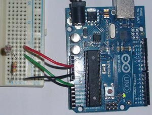
The photo below shows the assembled circuit on a breadboard. Voltages 0V and 5V are taken from Arduino. Pin A0 is used as an ADC input.
Below is an Arduino sketch. In this tutorial we simply turn on and off the LED that is built into the Arduino board. You can connect a brighter LED to leg 13 (via a ~220 Ohm resistor). If you connect a more powerful load, such as an incandescent lamp, then it should be connected through a relay or thyristor.
There are commented sections in the program code, they are used for debugging. It will be possible to control the ADC value (from 0 to 1024). Also, you need to change the value 500 (on and off threshold) in the code to the one you select experimentally by changing the illumination.
/* ** Night light ** ** www.hobbytronics.co.uk */ int sensorPin = A0; // set the input leg for the ADC unsigned int sensorValue = 0; // digital value of the photoresistor void setup() ( pinMode(13, OUTPUT); Serial.begin(9600); // start serial data output (for testing) void loop() ( sensorValue = analogRead(sensorPin); // read value from photoresistor if(sensorValue<500) digitalWrite(13, HIGH); // включаем else digitalWrite(13, LOW); // выключаем // Для отладки раскомментируйте нижеследующие строки //Serial.print(sensorValue, DEC); // вывод данных с фоторезистора (0-1024) //Serial.println(""); // возврат каретки //delay(500); }


