Polyvinyl chloride pipes are currently probably the most common material for creating indoor sewerage systems... Let's see how PVC sewer pipes are made, where they are used and what standards they are made by.
Physical and chemical properties of PVC
Let's start from afar. What is polyvinyl chloride? It is a colorless plastic resistant to alkalis, most acids and mineral oils. Does not burn in air; fully retains strength up to 65 C. At 150 - 220 C, depending on the brand, it melts.
The density of polyvinyl chloride is almost one and a half times higher than that of water - about 1.4 g / cm3. Dielectric.
What is key for us on this list?
- Dielectric... If so, no stray currents, no electric shock due to improper grounding of electrical appliances.
- Resistance to aggressive environments... Waste water itself is an aggressive environment; in addition, battery electrolyte and alkaline detergent can enter the drain.
- The temperature at which PVC loses its strength properties is quite low... If so, it is not suitable for drains with a high temperature.
Please note: the so-called chlorinated polyvinyl chloride has a higher operating temperature.
Pipes made of it can be used in an environment heated to 95 C, which makes it possible to produce from it not only pipes for PVC sewage, but also pressure pipes for hot water supply.
Pipes made of polyvinyl chloride are most often used for installing sewer systems in private houses, cottages and summer cottages. There are gray and brown models. Brown - Gray pipes are used to equip the internal structure. There is a catalog of sizes of PVC sewer pipes, as the pipes have different parameters. Their length can be from 0.5 to 6 m, and their diameter is from 16 to 500 mm. Pipelines are distinguished by increased strength, tightness, resistance to the influence of chemicals, the ability to withstand temperature extremes, ease and simplicity of installation. The material polyvinyl chloride increases the service life of the branch pipes up to 50 years. They are suitable for the implementation of internal and external sewerage systems, gravity drainage of sewage and external sewerage pressurized structures.
Characteristics of PVC PVC Piping
Pipe specifications include:
- internal pressure value - depends on the internal wall thickness, withstand 6-16 bar;
- specific gravity from 2 kg / l.m .;
- taking into account the inner diameter is necessary in order to calculate throughput pipeline, it must be measured taking into account the maximum distance between the inner planes of the nozzles;
- accounting for the outer diameter is determined by the wall thickness, it is necessary in order to choose mounting and insulating materials;
- wall thickness depends on the stiffness class of the fittings, it must be determined in order to understand the degree of protection of the structure from external mechanical influences;
- nominal bore is used to indicate the nominal bore;
- the weight of the structure is determined in order to understand the amount of material that is spent on manufacturing;
- the length of the structure is necessary in order to understand what longitude the pipeline will have. For example, the minimum length should be 1 m and the maximum can be 6 m.
GOST pipes for sewerage
The use of polyvinyl chloride in production plastic pipes made a real revolution in plumbing works, which are carried out in private and industrial volumes. According to the requirements of GOST, PVC pipes for sewage are designed for transporting household and industrial wastewater to domestic septic tanks or central highways. At the same time, there are a number of requirements both for the products themselves and for the conditions of their operation. Only if they are observed, pipelines can last 50 years or more, without maintenance, replacement and repair.
Specifications
GOST of PVC sewer pipes sets these products a number of parameters that are necessary for the safe and trouble-free operation of structures assembled from it. In addition, the main specifications plastic sewer pipes must comply with the current construction, sanitary standards and rules.
GOST of PVC sewer pipes defines the following criteria for these products:
- Place of use. Products are divided into internal and external. According to GOST, polyvinyl chloride pipes internal sewerage colored in grey colour and are used to collect and drain wastewater from premises. According to GOST, PVC pipes for external sewerage are colored orange, can be located underground and on the surface. External products are used to create stormwater, collector and drainage systems.
- Environmental conditions. According to this classification, PVC products are divided into pressure, non-pressure and corrugated. According to GOST, non-pressure PVC pipes for sewage can be installed only in those places where liquids will be transported by gravity at a relatively low speed. Pressure systems are designed to be exposed to a fairly strong internal and external pressure, which can be ± 10 atmospheres. Corrugated sections are intended for laying highways on curved sections. They can be manufactured both in pressure and non-pressure versions.
- Stiffness class. According to GOST, PVC pipes for sewage have 3 hardness classes (light, medium, heavy). This allows the use of polymer products in a wide variety of conditions, from a riser in a multi-storey building, to a highway laid under a road or construction site. This information is printed on all pipes as standard markings.
- Dimensions. These indicators directly affect the order of assembly and the throughput of systems. According to GOST 1898-2001, PVC sewer pipes must have a certain length, wall thickness, weight, inner and outer diameter. So, the length of the sections varies within 50-300 cm, the outer diameter of the internal and external lines is 100-110 mm and 110-250 mm, respectively. The wall thickness of the products is 2.2-3.6 mm.
- Connection method. According to GOST, plastic sewer pipes are joined in sockets or welded. Welding is used to join sections and fittings of external pressure systems. A socket connection is used in the assembly of non-pressure risers. Sealing collars and sealants are used to create reliable joints.
On a note: Provided that the GOST of plastic sewer pipes fully corresponds to the declared parameters, the result of the assembly work will be structures with ideal performance.
The advantages of plastic drainage systems
PVC pipes for sewage that comply with GOST have an extensive list of very significant advantages:
- Durability. Unlike metal counterparts, polymer systems do not corrode. This means that they are not threatened with thinning and loss of integrity. The outer surface of the line does not need to be painted and treated against rust.
- Low weight. This factor directly affects the cost of construction and repair. The products do not weigh down the weight of the building, which saves on the foundation and walls. In addition, even sections with a diameter of 250 mm can be operated manually without the need for lifting equipment.
- Smooth inner surface. Dirt and lime deposits do not settle on it. Even abrasive particles pass through the wastewater system without delay or friction.
- Elasticity. GOST pipes allow bending of the mainline under the influence of external factors, such as heaving of soil or shrinkage of buildings. Thanks to this, the pipeline remains functional and tight.
- Biological and chemical inertness. Mold and mildew do not form on polymer plastic. The material is resistant to acids, alkalis, solvents and other aggressive substances. This makes it possible to install PVC sewer pipes corresponding to GOST at enterprises, factories and workshops.
- Environmental and fire safety. Even when hot water is passed through, the sewage system does not emit harmful substances. PVC does not support combustion. The chlorine component causes the polymer to fade in the absence of a flame.
We should also dwell on the cost of the material. It is several times lower than that of steel products. This determines the high popularity of plastic pipes that meet the requirements of GOST.
Video about the installation of plastic sewer pipes
INTERSTATE COUNCIL FOR STANDARDIZATION, METROLOGY AND CERTIFICATION
INTERSTATE COUNCIL FOR STANDARDIZATION, METROLOGY AND CERTIFICATION
INTERSTATE
STANDARD
UNPLASTICED POLYVINYL CHLORIDE COATS AND SHAPED PARTS FOR INTERNAL SEWERAGE
Technical conditions
(ISO 3633: 2002, NEQ) (EN 1329-1: 1999, NEQ)
Official edition
Standardinform
Foreword
The goals, basic principles and basic procedure for carrying out work on interstate standardization are established in GOST 1.0-92 “Interstate standardization system. Basic provisions "and GOST 1.2-2009" Interstate standardization system. Interstate standards, rules, recommendations for interstate standardization. Rules for Development, Acceptance, Update and Cancellation "
Information about the standard
1 DEVELOPED by LLC "STC Systems of pipelines made of polymer materials" with the participation of LLC "RusVinyl"
2 INTRODUCED by the Technical Committee for Standardization TC 465 "Construction"
3 ADOPTED by the Interstate Council for Standardization, Metrology and Certification (Minutes No. 44-2013 dated November 14, 2013)
4 By order of the Federal Agency for Technical Regulation and Metrology dated December 30, 2013 Ne 2382-st, the interstate standard GOST 32412-2013 was put into effect as a national standard of the Russian Federation from January 1, 2015.
5 This standard is in accordance with the international standard ISO 3633: 2002 Plastics piping systems for soil and waste discharge (low and high temperature) inside buildings - Unplasticized poly (vinyl chloride) (PVC-U) (Plastics piping for discharge of wastewater (low and high temperature) inside buildings - Unplasticized polyvinyl chloride (PVC-U) and European standard EN 1329-1: 1999 Plastics piping systems for soil and waste discharge (low and high temperature) within the building structure - Unplasticized poly (vinyl chloride) (PVC-U) - Part 1: Specifications for pipes, fittings and the system. and high temperatures) inside buildings - Unplasticized polyvinyl chloride (PVC-U) - Part 1: Specifications for pipes, fittings and systems).
Compliance - Non-Equivalent (NEQ)
6 INTRODUCED FOR THE FIRST TIME
Information about changes to this standard is published in the annual information index "National standards". and the text of changes and amendments is in the monthly information index "National Standards". In case of revision (replacement) or cancellation of this standard, the corresponding notice will be published in the monthly information index "National Standards". Relevant information, notice and texts are also posted in the public information system - on the official website of the Federal Agency for Technical Regulation and Metrology on the Internet
© Standartinform, 2014
In the Russian Federation, this standard cannot be reproduced in whole or in part. replicated and distributed as an official publication without the permission of the Federal Agency for Technical Regulation and Metrology
INTERSTATE STANDARD
PIPES AND FITTINGS FROM UNPLASTIFIED POLYVINYL CHLORIDE FOR INTERNAL SEWERING SYSTEMS
Technical conditions
Unplasticized polyvinylchloride pipes and fittings for waste discharge inside the buildings. _Specifications_
Introduction date -2015-01-01
1 area of \u200b\u200buse
This standard applies to pipes and fittings made of unplasticized polyvinyl chloride PVC-U (PVC-U) with a solid wall, intended for sewage systems for the disposal of domestic waste water and storm sewers inside buildings.
2 Normative references
This standard uses normative references to the following interstate standards:
** On the territory of the Russian Federation, GOST R ISO 3126-2007 is in force.
3.5 medium outside diameter d, m, mm: Measured outer circumference of a pipe or pipe end of a fitting in any cross-section, divided by l (i \u003d 3.142), rounded up to 0.1 mm.
3.6 average inner diameter of the socket d im, mm: Arithmetic mean of measurements of the inner diameter of the socket in one cross section.
3.7 ovality difference between the measured maximum and minimum outside diameters in the same cross-section of a pipe or pipe end of a fitting
3.8 wall thickness e, mm: The result of measuring the wall thickness at any point along the circumference of the product.
3.9 average wall thickness e t, mm: Arithmetic mean of several measurements of wall thickness at points uniformly distributed around the circumference in one cross-section of the product, including the measured minimum and maximum values \u200b\u200bof wall thickness in the same cross-section.
3.10 pipes and fittings with a solid wall: Pipes and fittings with a smooth outer and inner surface, having the same composition over the entire wall thickness.
4 Main parameters and dimensions
4.1 Pipe dimensions
4.1.1 The average outer diameter d am shall correspond to table 1.
Table! In millimeters
|
Nominal size DN / OD |
Nominal outer diameter d n |
Average outer diameter d am |
|
|
minimum d am t u |
maximum P at |
||
4.1.2 Out-of-roundness, measured immediately after production, should not exceed 0.024d „.
4.1.3 The wall thickness should be in accordance with table 2.
Allowed wall thickness at any point no more than 1.2e mm, provided that the average thickness
the thickness of the wall e m is not more than e ^, ax.
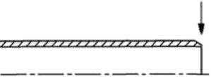
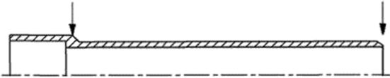
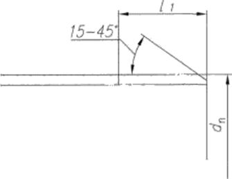
4.1.4 Pipe length / (effective), measured in accordance with Figure 1, shall be specified by the manufacturer. The maximum length deviation is ± 10 mm.
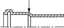
a) Pipe with a socket for an O-ring
b) Pipe with a socket for glue connection
L_______________i
c) Pipe (chamfered)
d) Pipe (no chamfer)
Figure 1 - Effective pipe length
4.1.5 When manufacturing pipes with a chamfer, the chamfer angle should be from 15 ° to 45 ° to the pipe axis. The residual wall thickness at the end of the pipe must be at least 1 / 3e m \u003d n.
4.2 Dimensions of fittings
4.2.1 The average outer diameter d am of the pipe end shall correspond to table 1.
4.2.2 The minimum wall thickness e mln of the body or pipe end must correspond to Table 2. A decrease in the wall thickness by 5% is allowed, while the arithmetic mean of the thickness of two opposite walls must be at least e t.
For transitional fittings intended to connect pipelines of two different nominal sizes, the wall thickness of each socket (pipe end) must meet the requirements for the corresponding nominal size. In this case, the design of the wall provides for a smooth change in thickness from one value to another.
4.3 Dimensions of sockets and pipe ends
4.3.1 The dimensions of the sockets and pipe ends for glued joint (Figure 2) must correspond to Table 3.
The manufacturer shall indicate whether the socket is tapered or parallel. If the flare is parallel, the mean inside diameter of the flare, d itn, must be applied over the entire length of the flare. If the socket is tapered, the limit values \u200b\u200bfor dun shall apply at the mid-length of the socket at a maximum taper angle of 20 "(minutes) relative to the socket axis.
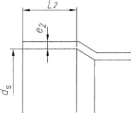
d t - inner diameter of the bell; Z., - the length of the pipe end; L 2 - the length of the bell; e g - wall thickness of the socket
Figure 2 - The main dimensions of the socket and pipe end for glue connection
|
Average internal height |
diameter of the pipe |
Length of socket L 2 and pipe end L, not less |
Wall thickness © 2. not less |
|
|
minimum |
maximum |
|||
For connections assembled at the factory. U values \u200b\u200bcan be reduced to C values.
indicated in table 4.
4.3.2 The dimensions of sockets and pipe ends for an O-ring (Figure 3 a)) must correspond to Table 4, 5 or 6 depending on the type of socket and pipe end (type S I, S II or M).
Various versions of the groove for the O-ring are allowed (Figure 3 b)), provided that the characteristics of the connection meet the requirements specified in table 11.
Socket dimensions, including maximum average inner diameter dun, max. And KE-navki under the O-ring must be installed by the manufacturer in the design and technical documentation on the product.
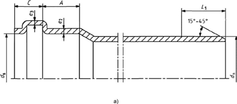
dt is the inner diameter of the socket; A is the minimum contact length; C is the depth of the point of effective compaction; Li is the length of the pipe end; e? - socket wall thickness; vz - wall thickness in the area of \u200b\u200bthe groove for the sealing ring
Figure 3 - The main dimensions of the socket and pipe end for an o-ring
Table 4- Socket and pipe end type S I (short type I)
In millimeters
|
Nominal outer diameter d n | ||||
Table 5- Socket and pipe end type S II (short type II)
In millimeters
|
Nominal outer diameter d n |
Average socket diameter (minimum) |
A. not less |
C, no more |
Li, not less |
Table 6- Flare and pipe end type M (middle)
In millimeters
|
Nominal outer diameter d n |
Average socket diameter (minimum) |
Li, not less |
||
If the o-ring creates more than one sealing point (figure 4). then the minimum A value and the maximum C value are measured from the effective sealing point as specified by the manufacturer.
Figure 4
Wall thickness e 2 and e 3 of the sockets for the O-ring (Figure 3 a)) must correspond to table 7.
It is allowed to decrease the thickness of the wall e 2 and e 3 by 5%, while the arithmetic mean of the thicknesses of two opposite walls should be not less than the values \u200b\u200bgiven in table 7.
Table 7_In millimeters
|
Nominal outer diameter with / „ |
Wall thickness, not less |
|
In socket designs where the O-ring is held by a cover (Figure 5), wall thickness e 3 should be calculated by adding the socket wall thickness and the cover wall thickness in the corresponding cross-section.
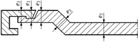
Figure 5 - Wall thickness of the socket with a cover for installation o-ring
4.3.3 Dimensions of L-type O-ring socket (long) and pipe end for
expansion joints for adhesive joints must comply with table 8.
Table 8- Flare Type L (Long) and Pipe End for Expansion Adhesive Nipples
In millimeters
|
Nominal outer diameter d n |
Average socket diameter (minimum) |
A, not less |
C, no more | |
4.4 Types of fittings
Fittings are made by injection molding. Fittings are made for O-ring connection and for adhesive connection.
This International Standard is applicable to the following main types of fittings:
a) bends (Figure 6) are produced in the following versions:
Pipe end-socket or socket-socket;
Bend curved (with radius R).
The nominal angle a for the bends is selected from the following values: 15 °, 22 ° 30 ", 30 °, 45 °, 67 ° 30 'and from 87 ° 30" to 90 °;
b) double-socket couplings and sliding couplings (Figure 7);
c) transition pipes (Figure 8);
d) tees and transition tees (Figure 9) are produced in the following versions:
Pipe end-socket-socket or socket-socket-socket;
Curved tee (radius R).
The nominal angle a for tees is selected from the following values: 45 °, 67 * 30 "and from 87 * 30" to 90 °.
Other types and designs of fittings are allowed.
The installation length z of the fittings must be specified by the manufacturer. Fitting length z of fittings is not used for quality control.
The design and nomenclature of fittings should be established in the manufacturer's design and technical documentation.
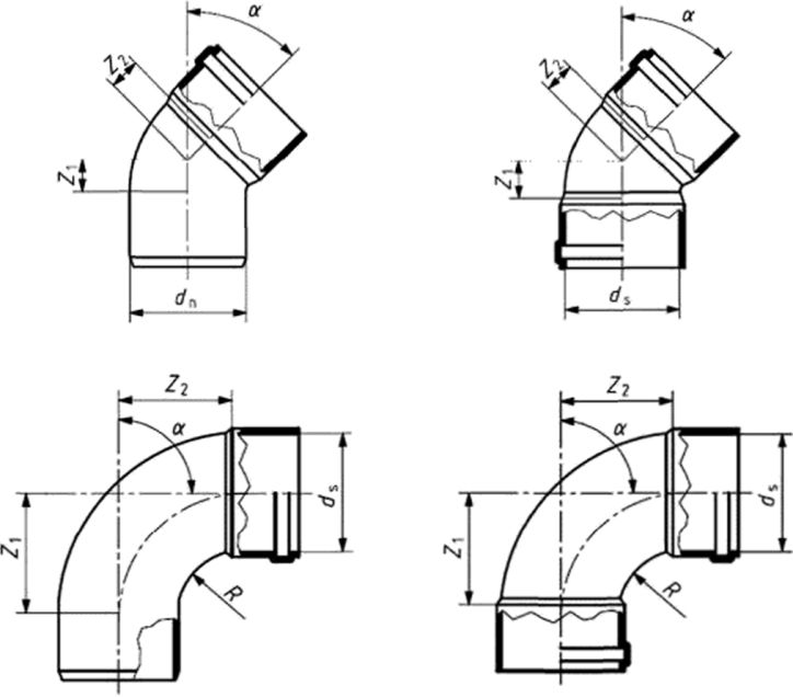
Figure 6 - Branch
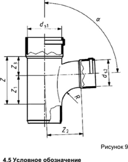
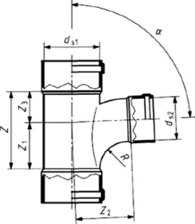
Figure 9 - Tee
4.5.1 The symbol of pipes includes:
The word "pipe";
Nominal size (nominal outside diameter) and nominal wall thickness;
4.5.2 The designation of the fitting includes:
The name of the fittings;
Abbreviated name of the material: Latin PVC-U or Cyrillic PVC-U;
Nominal size (nominal outside diameter);
Designation of this standard.
Examples of symbols:
Pipe with a nominal outer diameter of 160 mm and a nominal wall thickness of 3.2 mm:
Value
Test Method
1 Impact strength at a temperature of 0 ° С 11
2 Impact strength at 0 ° C (stepwise method)
Н50 & 1000 mm (no more than one destruction at a drop height of £ 500 mm)
3 Changing the length of the pipes after heating. %, no more
(there should be no bubbles or cracks on the pipes after heating)
Note - The manufacturer is not responsible for the marking that has become illegible as a result of the following actions during installation and operation: painting, surface cleaning or the use of detergents, except those agreed or established by the manufacturer.
When marking by printing, the color of the marking must be different from the color of pipes and fittings. The size of the lettering and the quality of the marking should ensure its legibility without the use of magnifying devices.
When marking by thermal embossing, the indentation depth should be no more than 0.25 mm.
5.4.2 Each pipe segment must be marked at intervals of not more than 1 m and contains: name and (or) trade mark of the manufacturer, symbol without the word "pipe", date (year and month) of manufacture.
It is allowed to include additional information in pipe marking, for example, shift number and batch number. For pipes that meet the requirements for impact strength by the stepwise method (table 9. indicator 2), the mark F - "snowflake" may be indicated in the marking.
5.4.3 The marking of fittings is made on the outer surface of each product and includes: the name and (or) trademark of the manufacturer, the symbol of the fittings without the name of the fittings, the date of manufacture (year).
The designation of this standard, the name of the fittings, the date of manufacture may be indicated on a label that ensures the safety of the marking during transportation, storage and installation.
5.4.4 Each package must be marked with transport markings
Pipes and fittings are resistant to destruction in atmospheric conditions. Unplasticized polyvinyl chloride waste generated during production is non-toxic and recyclable. Waste unsuitable for recycling is subject to destruction in accordance with sanitary rules providing for the procedure for the accumulation, transportation and disposal of industrial waste.
With regard to the use, transportation and storage of pipes and fittings, there are no special requirements for environmental protection.
6.4 In the production of pipes and fittings, fire safety requirements should be observed in accordance with GOST 12.1.004. In the event of a fire, extinguishing is carried out with fire extinguishing compounds, carbon dioxide, fire extinguishing powders, sprayed water with wetting agents, felt mat. To protect against toxic combustion products, insulating gas masks or industrial filtering masks of the M or BKF brand are used.
7 Acceptance rules
7.1 Pipes and fittings are accepted in lots. A batch is considered to be pipes or fittings of the same name and standard size (nominal diameter and wall thickness), manufactured
made from a composition of the same recipe composition and grades of components, on the same technological equipment, handed over simultaneously.
7.2 The quality document must contain:
Manufacturer's name and (or) trademark;
Product designation;
Batch number and / or date of manufacture;
Batch size;
Confirmation of compliance of products with the requirements of this standard.
7.3 To check the compliance of pipes and fittings with the requirements of this standard, acceptance and periodic tests are carried out in the amount indicated for pipes - in table 13, fittings - in table 14. connections - in table 15.
Table 13
|
Indicator name |
Requirements present standard |
control |
Control frequency | |
|
1 Appearance, marking |
Each batch | |||
|
2 Dimensions |
Each batch | |||
|
3 Impact strength at a temperature of 0 ° С p |
5.1.2. table 9 |
depending on d n, but not less than 2 |
||
|
4 Impact strength at 0 ° C (stepwise method) 11 |
5.1.2, table 9 |
Once every 12 months for the material used and each size group |
Not less than 10 |
|
|
5 Length change after warming up |
5.1.2, table 9 |
Once every 6 months for each size group | ||
|
6 Resistance to dichloromethane |
5.1.2, table 9 |
Once every 12 months for each size group | ||
|
7 Vicat softening point |
5.1.2, table 9 |
1 time in 12 months for the applied material | ||
|
"Impact strength is determined by one of the specified methods. |
||||
Table 14
|
Name indicator |
Requirements present standard |
Control frequency | ||
|
1 Tightness (watertightness) of connections |
5.1.4. table 11 |
Once every 12 months for each group of sizes and connection design "1 | ||
|
2 Tightness (airtightness) of connections |
5.1.4. table 11 |
Once every 24 months for each group of sizes and connection design '1 | ||
|
3 Tightness of joints under cyclic exposure to elevated temperatures 21 |
5.1.4. table 11 |
Appendix A |
At first release and redesign of connection 11 | |
|
"The design of the connection is determined by the design of the sealing ring, the shape of the groove for the ring, the hardness of the ring (± 5 units). 21 Definition of the indicator is optional. |
||||
7.4 The selection of samples of pipes and fittings for acceptance tests is carried out from the batch by the method of random selection. It is allowed to take samples evenly during the production process.
For periodic tests, samples are taken from batches that have passed acceptance tests, grouping products according to tables 16 and 17.
Table 16
Table 17
|
Group of types of fittings |
Name of fittings |
|
Tees |
|
7.5 If, during acceptance tests, at least one sample for any indicator does not meet the requirements of this standard, then repeat tests for this indicator are carried out on a double number of samples taken from the same batch. In case of unsatisfactory results of repeated tests, the batch of products is not subject to acceptance.
7.6 Upon receipt of unsatisfactory results of periodic tests, repeated tests are carried out according to the nonconformity indicator on a doubled number of samples. In the event of unsatisfactory results of repeated tests, the reasons that led to the nonconformity must be identified and eliminated.


