Send your good work in the knowledge base is simple. Use the form below
Students, graduate students, young scientists using the knowledge base in their studies and work will be very grateful to you.
Posted on http://www.allbest.ru/
Non-state educational institution
higher professional education
Moscow Technological Institute "VTU"
COURSE WORK
in the discipline "Foundations and foundations"
Save the list as you wish - the steel building is more convenient and affordable than ever. The construction of foundations and their depth depends on the nature of the structure, the construction system and the layout of the structure. The design and implementation of a particular type of foundation structure is mainly determined by the designer after consulting the statics. The calculation must take into account extreme loads such as floods or adverse wind effects. After considering all the facts, the designer chooses the appropriate way to create a family home from a technical and economic point of view.
"Design of foundations of buildings and structures"
Education level: Bachelor's degree
Direction: Construction
Profile: "Industrial and civil construction"
Completed: 2nd year student
A.A. Cheremnykh
Form of study: correspondence
Moscow 2016
foundation pile foundation
Initial data
In practice, this means that the design fundamentals are not overly broad, but rather bearable. We save not only construction Materialsbut also money. The depth of the foundation depends on the purpose of the object, the influence of the surrounding foundations and the loads occurring in the immediate vicinity.
The substrate must be at a freezing depth as freezing and thawing of the soil causes excessive settling. The depth of the foundation between the perimeter walls of the building may be less because there is no climatic effect. Even in basement houses, the freezing depth is taken into account, since the foundations are deep enough in the ground. The depth of the foundation is measured from base to base. Structurally, the foundations are flat and deep. In difficult geological conditions and in complex buildings, deep foundations are introduced: piles, columns, wells or chambers, which support the construction and are supported by the load-bearing soil.
Introduction
2. Development of options for the foundation F-2
List of references
Initial data
ANN: 053-12879
It is necessary to develop the foundation of the factory building.
Figure 1 - Construction scheme
Table 1 - Efforts on the edge of the foundation from the design loads
The initial characteristics of the soils are given in Table 2.
Table 2 - Characteristics of soils
It must be able to withstand the load at great depths because there are few supporting lands underground. We are not engaged in deep underground construction of houses. The quality of the assembled timber buildings has a long service life and technical quality comparable to other building systems, but only with strict adherence to the principles of correct implementation in all details. Basics are the key that influences the outcome of life and function of the object.
Essential questions for choosing the right funds
It is usually said that a building must have good foundations and good roof... Then the weather and elements will not be affected. So how do you choose the most suitable method? When deciding how to build a timber structure and type of foundation, be sure to answer the following questions.
|
Soil No. |
Name |
For deformation analysis |
Specific gravity of soil particles, S, kN / m3 |
Humidity, |
Deformation modulus, E, mPa |
Moisture at the pour point, L |
Moisture at the rolling edge, P |
Porosity coefficient, e |
Flow index, JL Does the bearing capacity and soil type in the depth of the foundation joint ensure the stability of all building elements?
|
Moisture degree, Sr |
|||
|
Specific gravity, II, kN / m3 |
Angle of internal discussion, II, deg |
Clutch, CII |
|||||||||||
|
Topsoil |
|||||||||||||
|
Loam Water must be removed from the foundationGeneral basic structural requirements state that the height of the lower edge of the walls of the building should be 150 to 300 mm from the surrounding area. This usually means one to two stairs before entering the house. Areas around the perimeter of the building must be neutralized. Drainage of rainwater is important, and it is provided with gradients - landscaping, where gravity directs surface water away from the building. In any case, we must prevent rainwater and melting snow to focus on, soak, and humiliate foundation structures. |
1 - Topsoil.
2 - Clay gray, silty, layered (strip).
2 - Gray sandy loam, light, weakly layered with lenses of sand.
3 - Dark gray brown loam, with lenses of sand, inclusions of pebbles (moraine).
Figure 2 - Geological section
Introduction
The design of foundations and foundations is one of the main parts of the design of buildings and structures in general. The choice of constructive and space-planning solutions of buildings largely depends on the engineering and geological conditions of the construction site and possible options for foundations.
Another important factor in the design and feasibility of a building is knowledge of the type and profile of the soil. Together with a test probe, we will determine the level of groundwater or the presence of springs in the area. The geological and hydrogeological profile can also be found in many existing maps.
We consider sandy gravel as a standard. The specifics of the dimensions of the foundation elements include clay, sandy and loose substrates, which are significantly less able to withstand a point load. In addition, in-field weights cannot be properly assessed in terms of bearing capacity and their compaction can be highly variable.
The need to deepen the foundation is dictated by a number of conditions. By deepening the foundation to solid soils, the reliable existence of the structure is ensured, both during construction and during its operation. Deepening below the heaving zone protects the structure from the effects of normal heaving forces, which can cause its deformation.
Elimination of plasticity and load changes due to unstable foundation soil and changes in its moisture content can be mainly flat foundation elements, which are then effectively transferred to superstructure pressure. The most common consequences of poor foundations in less abundant soils are uneven settlements, faults, or instability of vertical core members.
This fact, of course, affects the dimensions of the foundation structures. The static structure calculates the concrete type, dimensions and fitting of the fittings. Light type The top structure allows you to use the foundation to create many interesting ways besides the traditional ones. However, we always consider whether the design is wooden structure simple, skeletal, or if assembled out of frames. Thus, the effects transmitted to the base elements can be evenly distributed, axial or complementary.
The purpose of foundations - distribution of the load over a large area - follows from a comparison of the strength of the material above the foundation part of the structure and the strength of the soil. The strength of the soil is usually much less than the strength of the material of the structure, therefore the base of the foundation has dimensions larger than the dimensions of the structure.
The design of the foundations of buildings and structures is carried out according to two groups of limiting states.
How do we usually build wooden buildings?
The most common one is based on concrete foundations along with a base plate on which thermal insulation and superstructures are stored. The advantage is simple implementation, the disadvantage is the increase in the level of the future floor to the surrounding area, as well as the inevitability of a staircase or ramp at the entrance. A frequently used alternative is to place hardened extruded polystyrene insulation under the base plate. The base passes in this case also requires waterproofing and thermal insulation.
The purpose of the calculation for the I group of limit states is to determine the bearing capacity of the foundations, to ensure the strength and stability of the foundations for shear along the sole and overturning.
The calculation according to the II group of limiting states should limit the absolute and relative displacements of the foundations to the limiting values \u200b\u200bthat guarantee the normal operation of the structures.
Foam glass - a step closer to nature
The disadvantage is the increased need for cost, but the advantage is the ability to reduce the height difference between the clean floor and the relief of the surrounding structure. Low energy and passive buildings often use flat baseboards that transfer all vertical loads evenly. Thermal insulation stored under it. Elimination of thermal bridges in case of contact data as base plate, peripheral wall and ground, the main advantage of this type of foundation.
When designing foundations, it is necessary to calculate their bases for deformations in compliance with the condition that calculated precipitation were less than the maximum permissible values \u200b\u200bspecified in the building codes.
1. Structural characteristics of the building
The factory building located in Moscow has dimensions in plan
54 x 24 meters. Part of the building in axes 1 - 4 has a non-supporting frame - walls 0.38 m thick, but load-bearing wallslocated along the entire contour have a thickness of 0.51 m. The building has a basement with a depth of 2.7 m. The pitch of the columns along the building is 6 m, across the building is 12 m. The height of the building is 15 m. The ground level is at an elevation of -0,000 m.
Currently, extruded polystyrene is used as an insulator of appropriate strength or foam glass. This is the modern way to use modern technologies and stay in harmony with nature. The higher cost of implementation is in any case offset by superior technical parameters of this material. Buildings based on foam glass and reinforced concrete slab are currently the most modern ways lower structure settings.
The wire casing will provide more strength. The concrete reinforcement is inserted into the concrete so that the concrete structure is strong enough. Very good strength concrete structure in some cases can be achieved by adding steel fibers to fresh concrete. Since most current new construction of houses do without foundations, especially rigid reinforced concrete is increasingly used in the implementation of base slabs and strip foundations houses that can completely replace the reinforcing steel mesh.
1.1 Analysis of engineering and geological conditions
1st layer. The soil-vegetation layer has a low thickness, uncertain design characteristics and cannot serve as a basis.
2nd layer. The clay is gray, silty stratified tape. The thickness is about 4.0 m. According to the yield index JL \u003d 0.60, the clay is soft-plastic. Conditional design resistance R0 \u003d 165 kPa. By the value of the modulus of deformation E \u003d 3.5 MPa - highly compressible.
If we want to make the foundation cheaper and without any significant impact on the terrain, there is also the possibility of laying on concrete steps or steel rods. In this case, the quality of waterproofing solutions of the superstructure from the ground cannot be neglected, where more frequent condensation can be expected in the premises of the building.
A base is a structure made mainly of concrete or reinforced concrete with reinforcement elements on which the building is based. This term also refers to the underground part building wallslocated directly on benches or foundation slabs.
To use this soil as a base, we arrange a ground cushion. The compacted soil has specific gravity dry soil \u003d 17 kN / m3. Sealing thickness 2m.
We accept the conditional design resistance R0 \u003d 300 kPa (according to Appendix 3 of Table 2); e \u003d 0.58; \u003d 22.2 kN / m3. Subsidence characteristics \u003d 34 kPa; \u003d 22 deg. (according to Appendix 1 of Table 1). E \u003d 20 MPa.
3rd layer. Light gray sandy loam, slightly layered with lenses of sand. According to the yield index JL \u003d 0.55, the sandy loam is soft plastic. Conditional design resistance R0 \u003d 226 kPa. By the value of the modulus of deformation E \u003d 14 mPa - low compressible.
The base evenly distributes the weight of the building to prevent the structure from sliding and falling in the ground. First, a substrate is obtained. Humus is removed from the surface of the building, and then holes in the foundation are excavated. The most popular in single-family housing is the so-called. foundations. It is an extension at the bottom of the foundation walls, poured along their length, which are the main weight-bearing of the house. The base of the building evenly distributes the weight of the building to prevent slipping and collapse of the structure in the ground.
Single-family houses are relatively lightweight structures, therefore the so-called. shallow foundation. In addition to the benches mentioned, we also have legroom. They depend on the ground conditions of our conspiracy. The softer the soil, the deeper the earth should be. Clay soils are the most unfavorable in this respect, where a complete replacement of the substrate is required, which increases the cost of investment. In general, the depth of the foundations depends on the frost factor. It is important that they go deeper than the earth dies.
May serve as a basis.
4th layer. Dark gray heavy loam. According to the yield index JL \u003d 0.31, the loam is refractory. By the value of the modulus of deformation E \u003d 18 mPa - low compressible. Conditional design resistance R0 \u003d 285 kPa. It can also serve as a basis.
1.2 Options for the arrangement of the base and foundations
The following can be taken as preliminary foundation decisions:
Depending on the region, this will be from 80 to 1.4 meters below the ground. If we decide on a basement building, the depth of the foundations is determined by the height of the foundation. As you can see, the main thing. The popular and relatively unobtrusive foundation benches are poured onto the soil of good load-bearing capacity.
What do you need to know to avoid mistakes?
The type and depth of foundations depends on the ground conditions of our site. The bases are very difficult to grip and even more difficult to repair. So what, then, turn our attention to starting our great investment, which is building one family home?
1. Shallow foundation on a soil pad. Since the layer of soft soil has a great depth, measures to strengthen the soil are necessary to build a shallow foundation.
2. Pile foundation on hanging piles. This option is possible, since the third layer of soil has sufficient bearing capacity to serve as a base pile foundation.
3. Solid reinforced concrete slab under the entire building.
For the calculation, we accept options 1 and 2.
2. Development of options for the foundation F-2
2.1 Calculation of a shallow foundation
Determination of the depth of the foundation
The depth of the foundations df should be determined taking into account:
Based on the design features of the projected building, the depth of the foundation, m, is determined by the formula
where is the basement depth.
The standard depth of soil freezing, if it is less than 2.5 m, is determined by the formula
where is a coefficient numerically equal to the sum of the absolute values \u200b\u200bof monthly average negative temperatures for the winter in a given area. For Moscow \u003d 32.6;
Freezing depth in cm, depending on the type of soil. For loams and clays \u003d 23 cm.
The estimated depth of soil freezing is determined by the formula
where is the coefficient taking into account the effect of the thermal regime of the building on the depth of soil freezing at the foundations of walls and columns. takes according to the table. 3.1 MU. \u003d 0.6.
0.6 160 \u003d 96 cm.
Taking into account the great depth of the second layer, the need to pass the bulk layer and the high level of groundwater, we take the depth of the foundation to be minimal, but sufficient from the freezing conditions and design requirements.
We take the laying depth from the layout surface of 3.2 m.
Determination of the dimensions of the foundation sole
The foot area of \u200b\u200ba loaded foundation is determined by the formula
where is the design load applied to the foundation cut;
Design soil resistance of the foundation;
Average specific weight of soil and foundation masonry material, kN / m3, taken equal to 16 kN / m3 (in the presence of a basement);
The depth of the foundation from the planning mark, m
The calculation is carried out for the foundation 3.
The third layer is the carrier.
We accept the size of the sole of the foundation 3.9 x 3.6 m.
Determination of the design soil resistance of the foundation
The design soil resistance of the base, kPa, is determined by the formula
where and - coefficients of working conditions (Table 3.2 MU);
Reliability factor on the ground; \u003d 1;
Coefficients depending on the angle of internal friction (Table 3.3 MU); \u003d 1 for b< 10 м;
The average calculated value of the specific gravity of soils lying below the base of the foundation to a depth of 0.5b (in the presence of groundwater, it is determined taking into account the weighing effect of water), kN / m3;
The same, lying above the sole;
The depth of the foundations of basement structures from the level of the planning or the reduced depth from the basement floor determined by the formula
where is the thickness of the soil layer above the base of the foundation from the side
basement, m; - thickness of the basement floor structure, m; - the estimated value of the specific gravity of the basement structure, kN / m3.
Basement depth.
We clarify the dimensions of the base of the foundation
We increase the value of A by 10-20% for the perception of the moment of forces.
We finally accept the size of the sole of the foundation 3.0 x 2.4 m
We construct the foundation in accordance with the column dimensions, the depth of the foundation and the area of \u200b\u200bthe foundation base.
Figure 3 - Shallow foundation F-2
Determination of ground pressure under the base of the foundation
The calculated vertical load on the base soil under the foundation sole is determined by the formula
where is the calculated vertical load, the load on the edge of the foundation;
Fes foundation, which is determined by the formula
where is the volume of the foundation;
Specific gravity of reinforced concrete, which is 23 kN / m3.
Estimated weight of soil lying on the ledges of the foundation
3.0 · 2.4 · 0.6 + 2.4 · 1.8 · 1.8 \u003d 12.1 m3.
\u003d (3.0 · 2.4 · 3.2 - 12.1) / 2 \u003d 5.5 m3.
2540 + 12.1 * 23 + 5.5 * 18.2 \u003d 2918 kN.
Foundation height.
Average pressure under the foot of the foundation
where is the area of \u200b\u200bthe base of the foundation.
Maximum and minimum pressure under the foot of the foundation
where is the length of the foundation sole.
The following conditions must be met:
405 \u003d 461 kN / m2.
472 \u003d 553 kN / m2.
All conditions are met.
The base is overloaded with a margin of 12%, which is permissible.
Calculation of the base for deformations
The sediment by the layer-by-layer summation method is determined by the formula
where is the dimensionless coefficient, taken equal to 0.8;
n is the number of layers into which the compressible thickness is divided;
hi - thickness of the i-th layer; hi 0.4b;
zp, i - average vertical stress arising in the i-th layer;
Modulus of soil deformation of the i-th layer.
To calculate the settlement, we plot the diagrams of vertical stresses from the own weight of the soil and additional stresses along the axis of the foundation according to the formulas
where i is the specific weight of the i-th layer;
The coefficient taken depending on the values \u200b\u200b\u003d l / b and \u003d 2z / b we take pp of the table. 4.9 MU.
Additional vertical stress in the soil under the base of the foundation
where is the vertical stress due to the own weight of the soil at the level of the foundation sole. \u003d 18.2 * 3 \u003d 54.6 kPa; \u003d 405 kPa.
405 - 54.6 \u003d 350.4 kPa.
The specific gravity of soils that lie below the groundwater level, but above the aquiclude is determined taking into account the weighing effect of water.
Clays and loams of solid and semi-solid consistency at IL< 0,5.
In a waterproofing layer, the stress due to its own weight of the soil is determined without taking into account the weighing effect of water. The fourth layer is a waterproofing layer.
A voltage jump occurs at the boundary, equal to the pressure of the water column 10 · 2 \u003d 20 kPa.
The compressible thickness is limited by the depth, by
Table 3 - Calculation of foundation settlement
34.4 - the boundary of the compressible strata.
The maximum permissible draft according to SNiP 2.02.01-83 is 8 cm.
Calculated draft S \u003d 3.3 cm less than permissible
Figure 4 - Diagram of stress distribution in soil
Checking a weak sub-base
Checking the settlement of a weaker soil layer
where is the additional stress, which is calculated by the formula
where is the coefficient determined by the table. 3.4 MU.
The stress due to its own weight of the soil is determined by the formula
Design resistance of a weak soil layer at the point zn determined for a conventional foundation with a width bz
80.6 kPa (from the previous calculation).
2918/174 \u003d 16.2; \u003d (l-b) / 2 \u003d (3 - 2.4) / 2 \u003d 0.3
174 + 80,6 = 254,6 < 501 кПа.
The condition is met.
Calculation of the plate part for punching
We check the accepted height of the slab part by calculating the punching shear.
The condition must be met
where is the coefficient (for a monolithic conjugation of the column with the slab part of the foundation \u003d 1);
Design tensile strength of concrete (adopted according to SNiP). For concrete M 150 \u003d 630 kPa;
The arithmetic mean of the perimeters of the upper and lower bases of the pyramid formed during punching, within the working height of the section
Design punching force, kN
where is the area of \u200b\u200bthe polygon, m
Figure 5
0.5 3.6 (3.9 - 0.75 - 2 1.56) - 0.25 (3.6 - 1.8 - 2 1.56) 2 \u003d 0 m2.
0 268 \u003d 0 kN.
0 < 1·630·22.8·0,56 = 8044 кН
Condition satisfied
Checking the lower part of the step is reduced to determining
3.6 + 0.56 = 4.16.
0 < 630·0,56·4.16 = 1467 кН.
The takeaway of the lower stage should not exceed the value
0,6 < 3·0,56 = 1.68
The cross-sectional area of \u200b\u200bthe working reinforcement of the lower step of the foundation is calculated by the moment acting in the cross-section of the foundation along the edge of the column; in the sections along the edges of the steps, the sufficiency of the reinforcement adopted for this calculation is checked.
Moment in section 1-1
In section 2-2
0.000894 m2 \u003d 8.94 cm2.
We take the pitch of the rods 20 cm.When b \u003d 240 cm, the reinforcement (according to the assortment) is 1710, \u003d 10.49 cm2.
0.00122 m2 \u003d 12.2 cm2< 16,87 см2.
The accepted fittings are sufficient.
2.2 Calculation of the pile foundation
Determination of the depth of the base of the grillage
The depth of the sole is determined taking into account:
Purpose and design features of the projected structure;
Geotechnical conditions of the construction site;
Depths of seasonal soil freezing.
By analogy with calculating the depth of the shallow foundation, we take the depth of the pile grillage as 3.2 m.
Selection of the type and material of piles
The choice of piles is made taking into account the geotechnical features of the construction site.
We accept reinforced concrete driven piles square section with non-stressing reinforcement. By the nature of the work we accept hanging piles.
The length of the pile, based on the engineering and geological conditions, should be at least 8 m.
We choose a pile of the C8-35 brand. Length 8 m. Section 35x35 cm. Concrete grade B25. Longitudinal fittings А-I 412.
Determination of the bearing capacity of the pile
The bearing capacity of the pile is determined by the material of the pile and by the soil of the hanging pile.
The design resistance of the pile by material is determined by the formula:
where is the longitudinal force from the design loads;
Coefficient of working conditions (For d\u003e 20 cm \u003d 1);
Coefficient taking into account the peculiarities of loading (for a pile completely in the ground \u003d 1);
Design resistance of the reinforcement to compression;
Design resistance of concrete under axial compression;
Cross-sectional area of \u200b\u200bthe pile;
Cross-sectional area of \u200b\u200breinforcement.
The design resistance of the hanging pile on the ground is determined by the formula:
where is the coefficient of pile working conditions; \u003d 1;
Pile bearing area;
Design resistance under the lower end of the pile (Table 4.3);
The outer perimeter of the pile, m;
Design resistance of the i-th layer of the foundation soil along the lateral surface of the pile (according to Table 4.4);
The thickness of the i-th layer of soil in contact with the lateral surface of the pile;
Coefficients of working conditions under the lower end and along the lateral surface of the pile, depending on the method of driving the pile (according to SNiP 2.02.03-85 Table 3); \u003d 1, \u003d 1.
As the bearing layer of the hanging pile, we take layer 5 (dark gray, heavy loam).
Figure 6 - Scheme for calculating a hanging pile for bearing capacity
Divide the soil layers cut by the pile into strips no more than 2 m thick. We calculate the average depths zi for each layer and determine the value depending on the characteristics of the soil.
z1 \u003d 4.0 m; \u003d 14; \u003d 28.
z2 \u003d 4.0 m; \u003d 23; \u003d 46.
z3 \u003d 8.0 m; \u003d 45; \u003d 90.
z4 \u003d 10.0 m; \u003d 47; \u003d 94.
Determining the required number of piles
The required number of piles is determined by the formula
where is the design load for the first limiting state;
Reliability factor, which is equal to 1.4, if determined by calculation;
The bearing capacity of the pile;
Pile cross-section area;
The depth of the grillage;
The average specific gravity of the material of the foundation grillage and soil, we take \u003d 20 kN / m2.
Taking into account the effect of the moment, it is necessary to increase the number of piles by 20%
We accept 5 piles.
Design and calculation of grillage
Figure 7 - Construction of the F-2 grillage
Let's determine the actual weight of the grillage and soil on its ledges Nfr.
The volume of the grillage is 3.3 * 2.1 * 0.9 + 1.2 * 1.8 * 1.1 \u003d 8.42 m2.
The volume of soil on the grillage is 3.3 * 2.1 * 2.0 - 8.42 \u003d 5.44 m2.
Nfr \u003d 8.42 * 23 + 5.44 * 18.2 \u003d 293 kN.
2540 + 293 \u003d 2883 kN.
The moment acting on the base of the foundation is determined by the formula
where is the moment acting along the edge of the foundation;
Horizontal shear force;
Foundation height.
Eccentricity of the resultant relative to the center of gravity
Checking the pile foundation according to the first limit state
A single pile in the composition of the foundation and outside it in terms of the bearing capacity of the soil should be calculated based on the condition
Number of piles accepted;
and - design moments relative to the main axes in the plane of the grillage base;
and - the distance from the main axes to the pile axis;
and - the distance from the main axes of the pile foundation to the axis of each pile;
Estimated bearing capacity of the soil of the base of a single pile;
The reliability factor is taken equal to 1.4.
In the first row from the edge of the grillage
382,9 < = = 471 кН.
The condition is met.
The condition must also be met
where is the design resistance of the pile.
382,9 < 1065,2 кН.
Calculation of the grillage for bending with the selection of reinforcement
The cross-sectional area of \u200b\u200bthe working reinforcement of the lower step of the foundation is calculated by the moment acting in the cross-section of the grillage along the edge of the cup holder and along the edge of the column.
Moment in section along the edge of the cup holder
where is the pressure along the sole in section 1-1.
67.6 kN m.
69.3 kN m.
Reinforcement area for section 1-1
where is the working height of the slab part of the foundation;
Design tensile strength of reinforcement. For fittings of class A-II \u003d 270,000 kPa.
0.000323 m2 \u003d 3.23 cm2.
We take the pitch of the rods 20 cm.When b \u003d 240 cm, the reinforcement (according to the assortment) is 1110, \u003d 6.79 cm2.
By width
0.00033 m2 \u003d 3.3 cm2.
We accept the pitch of the rods 20 cm.When l \u003d 270 cm, the reinforcement (according to the assortment) is 1310, \u003d 8.33 cm2.
Checking the pile foundation according to the second limit state
When calculating the settlement, the pile foundation is conventionally taken as massive with a base located at the level of the end of the piles. Before determining the settlement, check the strength of the foundations at the level of the pile tip.
To determine the edges of the conditional array, we determine the weighted average value of the calculated angle of internal friction cf.
where are the calculated values \u200b\u200bof the angles of internal friction of the soil within the corresponding sections of the pile.
Draw planes from the edge of the extreme pile at the corners
The dimensions of the conditional foundation are calculated by the formulas
where, is the width and length of the conditional foundation;
Distance between the outer edges of the outermost piles.
Determine the design soil resistance under the ends of the piles
19.0 kN / m2.
Determination of the average actual pressure at the bottom of the conditional foundation
Dead weight of the conditional foundation
where is the weight of the piles; - weight of the grillage; - the weight of the soil.
Average actual pressure at the bottom of the conditional foundation
Conditional foundation area.
The weight of the grillage is determined by the formula
Soil weight
where; - the depth of the conditional foundation.
0.123 15 \u003d 1.85 m3.
22.8 11 \u003d 250.8 kN.
21.67 23 \u003d 498.4 kN.
5.6 6.6 12.5 - 21.67 - 8.13 \u003d 432.2 m3.
432 19.0 \u003d 8212 kN.
250.8 + 498.4 + 8212 \u003d 8961 kN.
448.3 < = 1458 кПа.
Calculation of the settlement of the pile foundation
This calculation is performed in the same way as for foundations on a natural foundation.
The soil massif is divided into elementary layers. The thickness of each layer should not exceed 0.4b \u003d 0.4 5.6 \u003d 2.24 m.
448.3 - 19.0 18.0 \u003d 106.3 kPa
b \u003d 5.6 m; l \u003d 6.6 m.
Table 4
The maximum permissible draft is taken as 8 cm.
The calculated draft S \u003d 3.66 cm. Less than the allowable one.
2.3 Calculation of the scope of work for two options of the foundation
Foundation volumes.
Shallow laying.
Pile.
V \u003d 21.67 m2. The volume of the grillage.
V \u003d 20.3 m2. Pile volume.
The pit volumes are determined according to the scheme
Figure 9
a \u003d 0.5m; d \u003d 0.3m; m \u003d 0.5 (for loams).
For shallow foundations
Vк \u003d 2.15 (5.26.1 + 7.35 8.25 + (5.2 + 7.35) (6.1 + 8.25)) / 6 \u003d 97.62 m3.
And add volume for the ground cushion device
Vp \u003d 0.3 (5.1 6.1 + 4.2 5.1 + (5.1 + 4.2) (6.1 + 5.1)) / 6 \u003d 7.83 m3.
For pile foundation grillage
Vк \u003d 2.15 * (5.2 * 4.3 + 7.35 * 6.45 + (5.2 + 7.35) * (4.3 + 6.45)) / 6 \u003d 73.34 m3.
Table 5 - Comparison of options for one foundation
Conclusion: for further calculations, we accept a pile foundation, since it requires less work.
2.4 Calculation of pile foundations
The depth of the laying, taking into account the presence of a basement for the entire building, is taken as 3.2 m from the design mark.
All foundations are for free-standing columns.
For foundations F-1, F-3 and F-4, we accept the S8-30 pile. It is 8 m long. Section 35x35 cm. Concrete grade B20. Longitudinal reinforcement А-I 412.
We define design resistance piles on the ground.
The immersion depth of the lower end of the pile is 12.2 m.
Design resistance R \u003d 3701 kPa.
(28 + 46 + 90 + 94) \u003d 816.4kN.
Determine the required number of piles.
We accept the number of piles - 4.
We accept the number of piles - 4.
3. Brief instructions for the production of work
Work on the vertical leveling and development of the excavation must begin immediately after obtaining the appropriate permits from the organization for earthworks.
We carry out water lowering with the help of open drainage and carry out the construction of foundations and other underground parts buildings located below the groundwater level until the loads from the structure exceed the resulting hydrostatic pressure and ensure stability underground structures from floating up.
When planning and designing a pit, the following safety rules must be observed:
The presence of people and the performance of any work in the area of \u200b\u200baction of earth-moving machines is unacceptable;
Excavator movements within the construction site should be planned earlier, and on soft soils reinforced with inventory boards;
During the break, the excavator must be moved from the edge of the excavation excavation at least 2 m, and the bucket must be lowered to the ground.
It is recommended to use bulldozers to excavate shallow pits (up to 1.5 m). The bottom of the pit, which is the basis for monolithic foundations must be developed with undershoot, without disturbing the natural structure of the soil.
Work on laying out pile axes and determining the locations of the centers can be performed by a foreman or a foreman who has a certificate for the right to carry out geodetic works.
You can start driving the piles only after all the preparatory and auxiliary work:
Arrangement of sites for the installation and dismantling of pile equipment;
Storage of piles and other structural elements of the underground part;
Verification of factory passports and pile markings;
Layout of sets of piles at the place of their immersion and their marking;
Installation and preparation for work of a pile driver and pile driving equipment.
Driving of piles, which act as struts, at the last stage of the submersion should be done with extreme care to avoid pile breakage. Failures of piles during the immersion process are recommended to be taken at least 0.2 cm, since smaller failures with prolonged operation of the hammer in this mode lead to the destruction of both the pile and the hammer.
Before installing the formwork, it is necessary to make a geodetic marking of the places of its installation in accordance with the working drawings of the monolithic grillage.
At the end of the installation of the frames, an act of readiness for receiving the concrete mixture is drawn up. The laid concrete mix must be compacted with vibrators.
At the end of the concrete hardening, the formwork is stripped and the removed formwork elements are cleaned, lubricated and stacked. Then be sure to check the marks of the top of the grillage and its geometric dimensions.
List of references
1. Guidelines for the implementation of term paper on the discipline "Foundations and Foundations", MTI "VTU".
2. SNiP 2.02.01-83. Foundations of buildings and structures. - M .: Stroyizdat, 1985.
3. Manual for SNiP 2.03.01-84 Manual for the design of reinforced concrete grillages of pile foundations for columns of buildings and structures.
4. GOST 25.100-96. Soils. Classification. - M .: Publishing house of standards, 1982.
5. SNiP 2.02.03-85. Pile foundations. - M .: TsITP Gosstroy USSR, 1986.
6. Manual for SNiP 2.03.01-85 - a manual for the design of reinforced concrete grillages of pile foundations for columns of buildings and structures.
7. Dalmatov B.I., Morareskul N.N., Iovchuk A.T., Naumenko V.G. Design of foundations for buildings and industrial structures. M .: ed. "High school", 1969. 269s.
Posted on Allbest.ru
...Similar documents
Analysis of soil conditions. Collecting loads on the foundation. Depth assignment. Determination of stresses and subsidence of the base under the wall section with a pilaster. Calculation of the base of shallow foundations by deformation. Pile foundation design.
term paper added on 05/07/2014
Assessment of engineering and geological conditions of the construction site. Consolidated statement of physical and mechanical properties of soils. Selection of possible options for foundations. Designing a shallow foundation on a natural foundation and a pile foundation.
term paper, added 12/08/2010
Assessment of engineering and geological conditions of the construction site. Development of types of foundations. Designing a shallow foundation on an artificial foundation. Pile foundation design. Determination of the influences of adjacent foundations.
term paper, added 10/21/2008
Analysis of engineering-geological and hydrogeological conditions of the construction site. Calculation of the settlement of the pile foundation by the layer-by-layer summation method. Determination of the depth of the foundation. Calculation of the size of the base of a shallow foundation.
term paper added 04/17/2015
Analysis of engineering and geological conditions of the site. Designing a shallow foundation on a natural foundation, an artificial foundation in the form of a soil cushion. Calculation of pile foundations, the depth of the foundation. Reinforcement of the structure.
term paper added on 10/04/2008
Assessment of engineering and geological conditions of the construction site. Determination of the depth of the grillage and the bearing capacity of the pile. Calculation of shallow foundations on a natural foundation and a pile foundation. Work production technology.
term paper, added 11/26/2014
Assessment of the geotechnical conditions of the construction site. The choice of the depth of the foundations to be built in open pit... Determination of the size of the soles of shallow foundations (on a natural basis). Calculation of the pile foundation.
term paper, added 12/13/2013
Analysis of engineering-geological and hydrogeological conditions of the construction site. Construction of a shallow foundation. Checking the pressure on the underlying layer of soft soil. Calculation of shallow foundation settlement and pile foundation.
term paper, added 02/16/2016
Shallow pile foundation design, pile foundation. Depth selection. Analysis of soil conditions. Preliminary dimensions of the foundation and design resistance. Bringing loads to the sole. Calculation of the volume and cost of work.
term paper, added 02/07/2013
Assessment of engineering and geological conditions of the site. Development of options for foundations. The depth of the sole. Calculation of the base settlement by the layer-by-layer summation method. Pile foundation design. The depth of the grillage, bearing capacity.
Foundation design includes a choice justified by calculation:
Base type (natural or artificial);
Type, construction, material and size of foundations (shallow or deep; tape, columnar, slab, etc.; reinforced concrete, concrete, rubble concrete, etc.);
Activities specified in subsection 5.8 applied when it is necessary to reduce the effect of deformations of the foundations on the serviceability of structures.
5.1.2. The foundations must be calculated according to two groups of limiting states: the first - according to the bearing capacity and the second - according to deformations.
The first group of limiting states includes states that lead the structure and foundation to complete unsuitability for operation (loss of stability of shape and position; fragile, ductile or other nature of destruction; resonant vibrations; excessive plastic deformations or deformations of unsteady creep, etc.).
The second group of limiting states includes states that impede the normal operation of a structure or reduce its durability due to unacceptable movements (settlements, rises, deflections, rolls, angles of rotation, vibrations, cracks, etc.).
The bases are calculated by deformations in all cases, except for those specified in 5.5.52 , and in terms of bearing capacity - in the cases specified in 5.1.3 .
5.1.3. The calculation of the bases for the bearing capacity should be carried out in cases where:
a) significant horizontal loads are transferred to the base (retaining walls, foundations of spacer structures, etc.), including seismic ones;
b) the structure is located on a slope or near a slope;
c) the base is composed of dispersed soils specified in 5.6.5 ;
d) the base is composed of rocky soils.
The calculation of the bases for the bearing capacity in the cases listed in subparagraphs "a" and "b" may not be performed if the design measures ensured the impossibility of displacement of the projected foundation.
If the project provides for the possibility of erecting a structure immediately after the foundations are installed before backfilling the sinuses of the excavations with soil, the bearing capacity of the foundation should be checked, taking into account the loads acting during the construction process.
5.1.4. The structure and its foundation must be considered in unity, i.e. the interaction of the structure with the base must be taken into account. Analytical, numerical and other methods can be used to jointly calculate the structure and foundation.
5.1.5. The purpose of calculating the foundations for limit states is to select a technical solution for foundations that makes it impossible for the base to reach the limit states specified in 5.1.2 ... In this case, not only the loads from the designed structure should be taken into account, but also the possible adverse effect of the external environment, leading to a change in the physical and mechanical properties of soils (for example, under the influence of surface or underground waters, climatic factors, various types of heat sources, etc.) ... Subsidence, swelling and saline soils are especially sensitive to changes in humidity, and swelling and heaving soils to changes in temperature conditions.
5.1.6. The design scheme of the "structure - foundation" or "foundation - foundation" system should be selected taking into account the most significant factors that determine the stress state and deformation of the foundation and structures of the structure (the static scheme of the structure, the features of its construction, the nature of soil layers, the properties of the foundation soils, their possibilities changes in the process of construction and operation of the structure, etc.). It is recommended to take into account the spatial work of structures, geometric and physical nonlinearity, anisotropy, plastic and rheological properties of materials and soils, the development of areas of plastic deformation under the foundation.
It is allowed to use probabilistic calculation methods, taking into account the statistical heterogeneity of the foundations, the random nature of the loads, effects and properties of the materials of structures.
5.1.7. The results of engineering and geological surveys, set out in the report, must contain information:
On the location of the territory of the proposed construction, its relief, climatic and seismic conditions and on previously completed engineering surveys;
On the engineering-geological structure of the construction site with a description in the stratigraphic sequence of soil strata, the form of bedding of soil formations, their dimensions in plan and in depth, age, origin and classification names of soils and indicating the identified engineering-geological elements ( GOST 20522);
On the hydrogeological conditions of the site, indicating the presence and thickness of aquifers and the regime of groundwater, marks of emerging and established groundwater levels, the amplitude of their seasonal and long-term fluctuations, water flow rates, information on the filtration characteristics of soils, as well as information on the chemical composition of groundwater and their aggressiveness towards materials of underground structures;
The presence of specific soils (see section 6 );
On the observed unfavorable geological and engineering-geological processes (karst, landslides, suffusion, mining operations, temperature anomalies, etc.);
On the physical and mechanical characteristics of soils;
Possible changes in hydrogeological conditions and physical and mechanical properties of soils during the construction and operation of the structure.
Foundations and underground structures should be designed on the basis of:
a) the results of engineering-geodetic, engineering-geological, hydrogeological and engineering-ecological surveys for construction;
b) data characterizing the purpose, design and technological features of the structure, operating loads and conditions and period of its operation;
c) a technical and economic comparison of possible design solutions for the adoption of an option that ensures the most complete use of the strength and deformation characteristics of soils and the physical and mechanical properties of materials for foundations and underground structures.
When designing foundations, foundations and underground structures, local construction conditions, surrounding buildings, environmental conditions, as well as existing experience in the construction and operation of structures in similar conditions should be taken into account.
The design of foundations, foundations and underground structures without an appropriate geotechnical and ecological justification or if it is insufficient is not allowed.
In the projects of foundations, foundations of buildings and underground structures of a higher level of responsibility, erected in difficult engineering and geological conditions, it is necessary to provide for: scientific support of design and construction; installation of the necessary instruments and devices for carrying out in-situ measurements of deformations, both under construction and reconstruction, and located near buildings and structures and the surface of the territory around them.
Full-scale measurements of deformations should also be provided in the case of using new or insufficiently studied structures of structures or their foundations, as well as if the design assignment has special requirements for measuring deformations.
The design stages of foundations, foundations and underground structures should be established by the customer and the general designer, depending on the complexity of the geotechnical and environmental conditions, the level of responsibility of the projected facility and the construction time frame.
The procedure for designing the O&F:
To study the materials of engineering-geological, hydrogeological and geodetic surveys at the site of future construction. (There must be a study of archival materials, especially in urban areas.)
Analyze the designed building in terms of assessing its sensitivity to uneven precipitation.
Determine the loads on the foundations.
Make an economic comparison of options and choose the cheapest one.
Perform a complete calculation and design of the selected foundation option.
The nomenclature of objects placed in underground space includes:
Utilities and structures: pipelines for various purposes, cable laying, general urban collectors, water supply and sewerage headworks, pumping stations, boilers, ventilation and heating chambers, transformer substations, central heating points, repair and maintenance complexes, etc.;
Engineering and transport facilities: transport tunnels of highways, pedestrian crossings, premises of bus stations and railway stations, parking garages;
Shopping and cultural and entertainment complexes, premises for entertainment and administrative buildings;
Trade enterprises, public catering, communal services and communications, warehousing and industrial facilities;
Main and auxiliary premises of the underground part of residential buildings;
Protective structures of civil defense;
Special structures.
Depending on the volume of the underground space occupied, these structures are subdivided into long linear (mainly engineering communications, transport tunnels) and compact (free-standing).
Underground and buried structures should be classified according to the method of their construction into: structures erected by an open method, and structures erected by a closed method.
Structures erected by an open method include those arranged:
In the embankment;
In pits with unsecured sides (slopes);
In pits with the use of temporary enclosing structures (sheet piles, pick-ups, dowels, etc.);
In pits with the use of permanent enclosing structures ("walls in the ground", bored piles, etc.);
In pits using special construction methods (freezing soils, fixing soils, etc.);
By the way of the sinking well.
The structures erected in a closed way include those arranged:
By mining method;
Combine and panel methods;
By squeezing.
The choice of a constructive solution and construction methods, underground and buried structures should be determined taking into account:
Purpose of the structure, space-planning solutions, depth of laying;
The values \u200b\u200bof the loads transferred to the structure;
Engineering-geological and hydrogeological conditions of the construction site;
Conditions of existing buildings and the impact of underground construction on them;
Mutual influence of the designed structure and existing underground structures;
Environmental requirements;
Technical and economic comparison of design options.
Selection of optimal solutions for the design of foundations and foundations.
Variety of solutions
Foundation construction is one of the most labor-intensive and material-intensive construction industries. According to NIIOSP * them. N.M. Gersevanov, the volume of foundation construction is on average about 10% of the total cost of construction and installation work. In difficult engineering-geological conditions (IGU), this figure reaches 30%. At the same time, the consumption of concrete and reinforced concrete during the construction of foundations reaches 23% of its total consumption in construction, and labor costs - 15 ... 20% (Reference.Research, Design and Survey and Design and Technological Institute of Foundations and Underground Structures (NIIOSP) named after N.M. Gersevanova is a leading organization in the construction industry in Russia in the field of foundation engineering and underground construction. NIIOSP was established in 1931 as the All-Union Institute for Complex Foundations and Foundations (VIOS), in 1958 it was approved as the leading institute of the construction industry in the field of foundation engineering and underground construction, in 1966 it was awarded the Order of the Red Banner of Labor. The Institute has been named after its founder, the outstanding Russian scientist Nikolai Mikhailovich Gersevanov, since 1973.
Almost all large objects of the country - high-rise buildings in Moscow, the Moscow metro, the Ostankinskaya TV tower, the Norilsk mining and metallurgical plant, large plants (Togliatti, Zaporozhye, Naberezhnye Chelny, Cherepovets, etc.), facilities for the development of ore, coal, oil and gas fields (Kursk, Vorkuta Urengoy, Yakutsk, etc.) were built with the participation of the Institute.
Unique objects in Cuba, Bulgaria, India, Egypt, Iran, Yugoslavia and other countries were also erected with the participation of the Institute).
The country's transition to a market economy made a matter of choice optimal solutions when designing bases and foundations, and therefore reducing the cost of their device, is especially relevant.
The development of an optimal design of foundations and foundations is possible on the basis of a feasibility study of the options under consideration at a minimum of the estimated cost, reduced costs and labor costs, as well as the duration of work.
Variant design of foundations and foundations of buildings and structures is a complex multifactorial task. The variety of climatic and engineering-geological conditions of real soil sites of future construction, the great variability of the characteristics of the physical and mechanical properties of the constituent soils, various design and technological features of buildings and structures lead to the need for an individual approach to the design of the foundation of each structure at each new construction site.
An additional complication of the problem of optimal design is the need to consider a wide range of structural types of foundations, primarily shallow foundations (columnar, strip, intermittent, cross, slab), and pile foundations that differ in material, design, manufacturing method, etc. In addition, in a variant consideration, in a number of cases, artificial foundations or deep foundations can be included.
This makes it necessary to use modern computers with specially developed software for variant design and selection of the optimal foundation, thereby placing most of the routine calculations on the computer. The designer is left with the creative, most responsible elements: drawing up a design scheme, preparing and entering initial data, analyzing the calculation results and making a final decision on the type and size of the foundation. One of the most important criteria for choosing the optimal foundation is its cost. Currently, a software package has been developed (for example, SPbGASU), which includes programs for calculating bases and foundations of four types (Fig. 3):
1) shallow on a natural foundation;
2) from prismatic driven piles;
3) on artificial grounds;
4) from bored piles.
At the same time, for each type of foundations, a multivariate calculation is carried out, which makes it possible to determine their technical parameters at different depths of the base, change the thickness of the artificial base layer, and for pile foundations - to enumerate the lengths and cross-sections of driven bored piles. A feature of the developed programs included in the software package is the calculation of economic indicators, which allows you to choose the most rational and economical foundation for a given soil bedding, loads, types and sizes. The optimal solution is found on the basis of a technical and economic comparison of options. Consideration of options is one of the main points of foundation design.
Feasibility comparison of options
The technical and economic comparison of the options is made by analyzing their technical and economic indicators. Economic efficiency (reduced costs, estimated cost, consumption of basic materials, etc.) in some cases is the main indicator when comparing options. In this case, compliance with the conditions of their comparability is of great importance (Fig. 3).
Fig. 3. Schematic diagram of a complex of programs for multivariate calculations
foundations of various types
The economic efficiency of the options is best calculated for the entire structure, determining the total cost of the foundations, but this requires detailed development of a large number of foundations. Therefore, for the analysis of indicators, a comparable unit of measurement can be selected, for example, 1 m 2 of the total area of \u200b\u200bthe structure, one separate foundation for a column, 1 linear meter. m of foundation for walls, etc. In this case, it is recommended to make a calculation for the most loaded typical foundation. Sometimes, with prevailing vertical loads, the cost of the foundation is referred to the unit load on the foundation (per 1 kN).
A fairly complete methodology for the technical and economic comparison of options for various types of foundations, which consists in calculating the cost and natural indicators for each option and choosing the best of them at a minimum of reduced costs, is presented in the "Guide" of the N. M. Gersevanov NIIOSP (1984).
The main cost criterion when choosing the optimal solution is the reduced cost indicator, determined for each option. It is recommended to determine the reduced costs З for various variants of foundations in reference books by the formula:
Z \u003d C + E (K 1 + K 2) + D, (1) where C is the actual cost of building foundations;
E-normative coefficient of comparative efficiency of capital investments, taken equal to 0.12; K 1 and K 2 capital investments in the main production assets of the construction industry (K 1 in enterprises for the production of ready-mixed concrete, reinforcement, precast concrete and reinforced concrete structures of foundations; K 2 in construction and transport machines and mechanisms, as well as in the base for their maintenance and operation); D is the factor that determines the scarcity of material resources.
With the introduction of market relations in the Russian Federation and the abolition of state regulation of capital investments in fixed assets, the second and third terms of the expression were included in the costs at the actual cost of construction.
The actual cost of construction is determined on the basis of the current estimate norms and "Unified District Unit Rates" (EPER), and the reduced costs are set according to the formula: З \u003d SC, (2) where C is the actual cost price; К is the coefficient of rise in prices caused by the liberalization of prices for building materials, structures, energy consumption, operation of machines and mechanisms.
The coefficient of market appreciation is determined for each construction organization and depends not only on the existing prices for building materials and energy resources at the time of calculation, but also on overhead costs, profitability and deductions in the form of taxes to the budget.
The cost of building options for foundations can be determined using the specific indicators of the cost of labor, given in table. 3.4 p.37
Optimization of the design of foundations and structures as a whole
When comparing the options technically and economically, one should not strive to determine the overly precise dimensions of each foundation. The results of variant design should not lead to a significant increase in the number of standard sizes of foundations. It is recommended to take piles of the same length for individual objects, if possible, set the depth of the individual and strip foundations to be the same. The dimensions of foundations and their details must correspond to the structural module or the inventory formwork module.
Sometimes, adopting a cheaper option can lead to the development of significant and uneven rainfall over many years. Equivalent solutions in this regard are those for which the same uneven settlement is expected, in any case, less than the maximum permissible values. This indicates that a simple comparison of cost options is not always permissible. An important reserve of savings in the construction of residential quarters is variant design at the stage of development of projects for quarter planning. In the present. Since then, a scheme has been developed (Fig. 4) for the design of rational foundations at the stage of the quarterly planning project, taking into account specific engineering and geological conditions (Mangushev R.A., SPb GASU, 1992).
According to this scheme, the territory of future construction is divided into conditionally homogeneous engineering-geological zones, which implies a denser network of engineering-geological wells. The breakdown into these zones is carried out according to the results of exploration drilling based on a special machine-oriented technique, according to which the initial data for the territory of the quarter are the number of exploration wells and their conditional coordinates, the explored thickness of the soil layers in each of them, the physical and deformation characteristics of the soil layers , the specified step of the conditional center grid within the quarter.
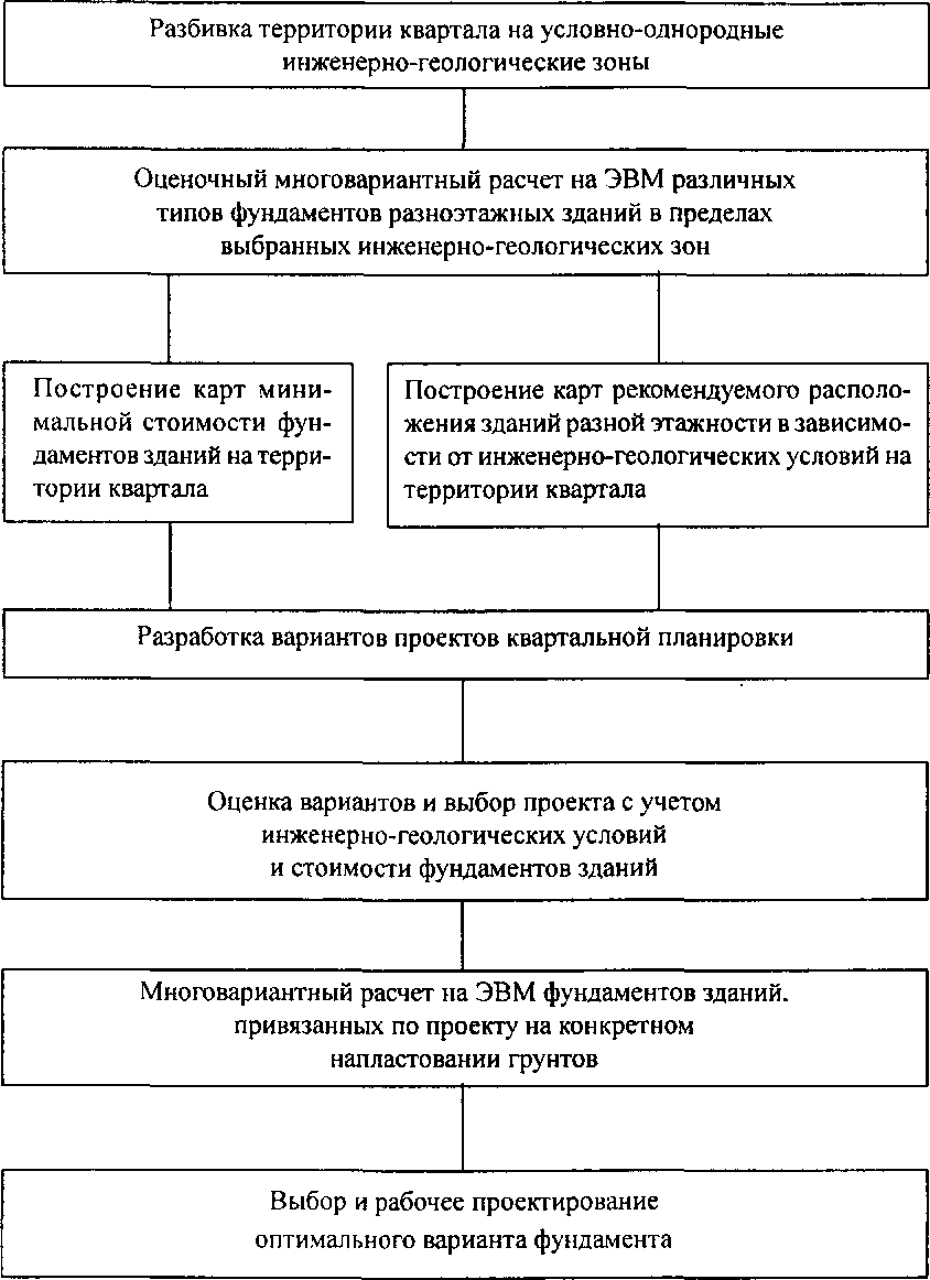
Figure: 4. Scheme for designing rational foundations at the stage of the quarterly planning project, taking into account the engineering and geological conditions
Conditionally compressible engineering-geological zones are understood as those parts of the quarter's territory, within which the soil strata have the same compressibility, are close in thickness and characteristics of the layers. In this case, each zone corresponds to engineering-geological information calculated with a certain degree of probability, which is subsequently used when carrying out calculations on a computer.
For these zones, a multivariate calculation is performed in accordance with the diagram shown in Fig. 3, of all possible types of foundations for the entire set of buildings scheduled for construction in this quarter.
For each type of foundation, a multivariate calculation is carried out, which makes it possible to determine their technical parameters at different depths of the sole, changing the thickness of the artificial base layer. For pile foundations, it is recommended to search the lengths and cross-sections of precast concrete piles. When calculating the economic indicators of all options, aggregated prices are used for performing zero cycle work. The results of automated calculations make it possible to construct a set of special geotechnical maps for typical buildings of various storeys, adopted during the development of the quarter, which reflect various types of foundations with a minimum cost for each of the zones, as well as their unit costs. Joint consideration of such maps allows us to construct a generalized map-diagram of the rational placement of buildings of different storeys in the quarter by the factor of the minimum cost of foundations. In fig. Figures 5 and 6 show fragments of such maps for one of the quarters in St. Petersburg.
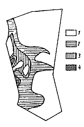
The results of multivariate calculations of foundations and their graphical representation in the form of special maps on a scale of 1: 2000 show the great possibilities of this approach to the design of foundations for mass development and rational placement of buildings of various storeys in the territory under consideration.
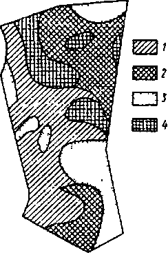
Fig. 6. Fragment of a schematic map of the recommended placement of buildings of various storeys on shallow foundations: 1-storey buildings are less than 6 floors: 2 - less than 9 floors; 3 or less than 12 floors; 4 or less than 16 floors of the quarter, the total cost of their underground part is reduced by 25 ... 30%.
Thus, when developing quarterly planning projects, along with the well-known urban planning factors to be taken into account, architects-planners have the opportunity to quantitatively assess the geotechnical conditions of construction sites in terms of the efficiency of foundations, which is one of the most costly areas of construction.
Technological schemes for the construction of the underground part of buildings on a natural foundation.
The construction of the underground part of buildings and structures is carried out on the basis of technological regulations (TR), which are drawn up on the basis of SNiP 3.01.01-85* Organization of construction production, SNiP III-4-80* Safety in construction, GOST 13579-78* Concrete blocks for basement walls, GOST 13580-85 Reinforced concrete slabs for strip foundations, VSN 37-96 Instructions for the construction of foundations on a natural basis for the construction of high-rise residential buildings, SNiP 3.02.01-87 Earthworks, foundations and foundations, SNiP 2.02.01-83 Foundations of buildings and structures, SNiP 3.01.03-84 Geodetic works in construction.
The most widespread are three technological schemes for performing work on the arrangement of the underground part of buildings, which differ from each other in the placement of mechanization means and the nature of their movement (Fig. 7).
When performing work on:
in the first technological scheme, the means of mechanization are placed at the bottom of the pit, directly at the structure being erected;
the second - at the edge of the pit and move around the pit along its perimeter;
the third, the same at the edge of the pit, but move only along one side of it.
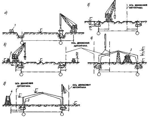
Fig. 7. Organizational and technological schemes for the construction of buildings and structures
When constructing buildings of complex configuration, the third technological scheme can be replaced with a horseshoe-shaped one. The rounding of the crane runways allows, with a hook outreach of 20-25 m, to provide with one crane the installation of all parts of the U-shaped and other buildings that are complex in plan. In this case, the radii of curvature of the rails are usually taken to be minimal, which requires ensuring high quality and accuracy of laying the crane runways and their careful operation.
The choice of schemes is determined by the specific conditions of work and the available fleet of construction machines. For the installation of the underground part of buildings from prefabricated elements on strip prefabricated foundations, in some cases it may be an effective scheme that provides for the use of a gantry crane (portal type) as an assembly mechanism. The required reach of the hook of erecting cranes, concrete pavers and other machines depends on the selected technological scheme, the location of the building structures in the plan, the size of the base or the track gauge of the machine and the permissible steepness of the slope of the excavation or trench. Organizational and technological schemes for the construction of buildings and structures, installation of a wall in the ground, construction of multilayer walls are shown in Fig. 8 - 11.
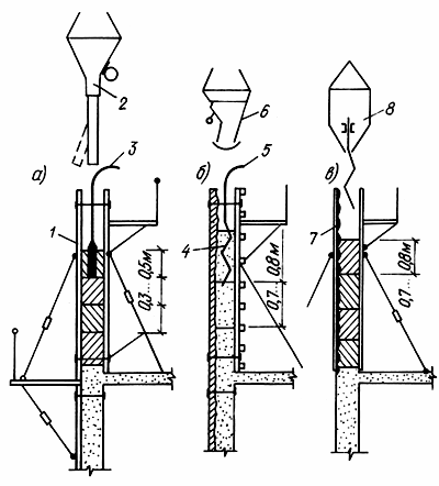
Fig. 8. Technological scheme for concreting the walls of the pit
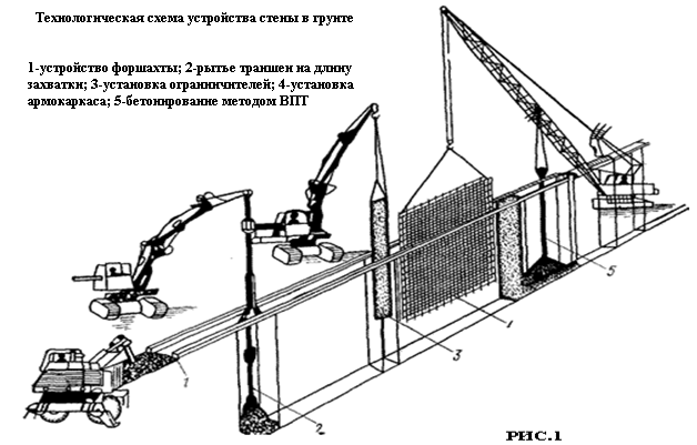
Figure: 9. Technological diagram of the device of the wall in the ground
![]()
Fig. 10. Technological scheme for the construction of multi-layer walls
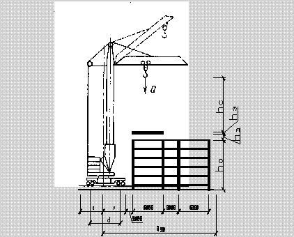
Figure: 11. The layout of the crane relative to the building


