In any building, the main elements to which the maximum load falls are the foundation, walls and roof. The quality of the installation of the roof largely depends on whether the device is executed correctly or not rafter system... If the attachment points of the rafter system do not meet certain requirements, then such a roof will not serve even the minimum operational life without repair work.
Requirements for the rafter system
The rafter system of any roof must meet such important requirements as:
- Maximum rigidity. Any unit of the frame must withstand the loads without being subjected to deformation or displacement. The triangle obtained when arranging the rafter system should ensure the rigidity of the structure, and its maximum stability;
- Optimal weight. Depending on the roofing material choose the material used for the rafters. Usually timber is chosen, but metal can be used for heavy roofs.
Important! To prevent damage to the rafters, their rotting and the formation of fungus on the wood, it is treated with an antiseptic, and metal structures - with anticorrosive compounds.
- High quality materials used. The wood used as rafter legs should be free from cracks and chips.
Varieties of rafter systems
The roof can be equipped with one of the types of rafter system, of which there are only two:
- Hanging rafters;
- Roof rafters.

Hanging rafter system

Such a system is optimal in the case of a gable roof, when the span between the walls is no more than 6 meters, but during installation additional elements applicable for wider openings. The Mauerlat serves as the lower base for the support, while the upper part of the structure abuts against each other. This design also contains a tightening - necessary to relieve the load from the walls, by reducing the spacing of the rafters. Beam ties are installed below the rafter legs and can function as floor beams.
Attention! The role of tightening can not necessarily be performed by a wooden beam, it can also be an overlap from reinforced concrete structures, which in some houses is equipped with the upper floor.
If the tightening is located above the bottom of the rafter system, then it is called a crossbar. The important points of arranging a rafter system of this type include:
- It should not be allowed that the roof overhang rests on the lower part of the rafter legs, which are displayed outside the wall. In such a situation, it is best to use a filly (the width of the overhang is set within one meter). With this arrangement, the rafter will rest on the Mauerlat. The cross-section of the timber for the filly is chosen smaller than for the rafters;
- To give the roof additional rigidity, and prevent it from wobbling and destruction by strong gusts of wind, a wind board is nailed to the slope, to the Mauerlat from the ridge;
- When the moisture content of the material used to equip the rafter system is more than 18%, precariousness should be provided, which will cause the wood to gradually dry out. That is why fasteners should be bolted or screws, not nails.
Rafter roof system

Such arrangement is applicable for roofs with distances between walls from 10 meters (maximum 16 meters). The slope can be made at any angle, and there are load-bearing walls or supporting columns inside the building. From above for the rafters, the ridge girder serves as the main support, and from below this function is performed by the Mauerlat. The internal run is maintained by or inner wall, or rack. Due to the presence of only vertical type of loads, there is no need for tightening installation.
With a 16-meter span, the ridge run is replaced with two side structures, for which the racks will serve as a support.
Important! The absence of bends of the rafter legs is ensured by such nodes as struts and crossbars.
Particular attention to the arrangement of the roof using a layered rafter system should be paid to the following nuances:

Features of calculations of the rafter system gable roof shown in the video:
The main nodes of rafter systems
The main nodes of the roof truss system include:
- Rafters. They function as a skeleton, supporting internal and external elements roofs, and also serve as the basis for laying communications;
- Mauerlat. This is a kind of roofing foundation, which is a beam on which the entire structure is installed. It performs an important function - even distribution of the load of the entire structure;
- Run. Designed for fastening rafter legs together and can be located both from above and from the side;
- Tightening. Serves to fix the rafters at the bottom of the structure;
- Braces and struts. Provide the most stable location of the rafter beams;
- Skate. The junction of the roof slopes;
- Filly. These are the extensions of the rafter legs, which are sometimes equipped;
- Rigel. It is necessary for high-quality and reliable support of load-bearing elements;
- Sill. Crossbar required for load distribution.
In addition to the listed elements, the structure includes attachment points for the roof truss system. When performing them, it is imperative to follow certain rules.

Important! It is absolutely not worthwhile to carry out a simple fastening of the base to the crossbar, as this can lead to the complete destruction of the rafter system.
The following types of fasteners should be used:
- With emphasis on the end of the crossbar;
- Teeth point-blank;
- Teeth into a thorn.
The number of teeth should be chosen depending on the slope of the slope, and additional structural reliability can be created using metal corners.
The main attachment points for the truss structure include:
- Beam node;
- Mauerlatny knot;
- Ridge knot.
Beam node
With such a knot for connecting the elements, an insert from teeth into a spike is made into the rafter, and a recess is made in the transverse section of the crossbar, corresponding to the teeth. Such a depression or nest should be no more than 30% of the timber thickness. Fastening is carried out with special hardware with metal corners, or wood beams, spikes and linings.
Attention! If the roof is made of materials with low weight, and the slope of its slope does not exceed 35º, then the bases of the supports should be placed in such a way that they rest against an area larger than the beam itself.
Mauerlat knot
Such fastening can be performed using either rigid technology or sliding. Rigid technology involves installing a strong connection between the Mauerlat and the rafters, preventing the possibility of slipping, bending or jumping out. For this, special support corners with bars are used. The resulting knot is fastened with wire using hardware. In this case, the nails should be driven obliquely so that they enter the wood crosswise. The last nail must be driven vertically.
In the case of a sliding mount, alignment is performed using a special mechanism that allows you to move the rafter leg in the required direction. For this, a tie-in is made on supports, on which the Mauerlat is then laid. The structure is fixed, as in the previous case, with crossed nails. This method of arranging connection nodes allows all nodes of the rafter structure to move within certain limits.
Attention! Rigid fastening with inexperience of builders can lead to damage to the walls of the building.
Ridge knot

In this case, the fastening can also be performed in two types - butt and overlap. With a butt joint, the top of the supports is cut off with a bevel, as well as the angle of inclination of the roof. They are supported by the same clipped opposite supports. Fastening is carried out using nails, in the amount of two pieces. They are hammered from above at a certain angle. The seams that form between the supports are connected with metal strips or plates. In the second case, the fastening is performed by overlapping, not by the end parts, but by the side sections and are fixed with bolts.
Conclusion
When carrying out work on the installation of the roof, the arrangement of the rafter system, careful attention should be paid to prevent disruption of technological processes. This will provide the structure with strength, durability and reliability.
At the beginning of the planning of the attic roof, a rafter system is selected that acts as a supporting structure. The type of truss system required is determined based on the type of roof.
Depending on the system chosen, these can be wooden beams used as a roof frame that holds the composite building materials of the entire structure, or specific elements that create supports, called rafter legs. Before starting work, the wooden components are impregnated with special compounds that protect the roof from fire and decay. The durability of the roof directly depends on the quality of this procedure.
Varieties of rafter systems and the device of their nodes
The rafter system is divided into two main types: layered and. Since the connection points in each of the systems have different characteristics, a certain type of rafter is selected based on the properties of the preferred roof, including its architectural features.
The main factors when choosing the right type of system:

- general roof functionality;
- the force of pressure of roofing building materials on the structure;
- the prevalence and frequency of precipitation in the territory where the house is located.
The hanging type of rafters does not have supports located in the gaps. For this reason, a reinforced thrust appears, which is transmitted horizontally to the walls of the building. To reduce this indicator, a tension member made of wood or metal is introduced into the support assembly, designed to combine the rafter legs. Thus, the nodes of the hanging rafters take the shape of a triangle. The tightening element is located at the base of the legs, it acts as a crossbar (most often used in gable roof structures) and works in bending and compression. The strength of the connection with the base of the supports depends on the height of the tightening element.

The overlapping type of rafters is often set up in buildings where there is a central support column or load-bearing wall. The rafters rest their limbs against the sides of the building, and the central part rests on a column or other support inside the house. Such a structural unit is designed for bending function. Inclined supports create less stress on the components of the building, so their installation is not as laborious as in the case of hanging rafters... In addition, it does not require large material costs.
There are also roof options that combine both types of rafters. In this case, each type alternates, that is, areas without bearing walls are equipped with hanging rafters, and areas with the necessary supports are layered.
Competent arrangement of the rafter system
The main factor in the high strength of the roof in the future construction is the competent arrangement of all nodes and anchor points.
In the case of layered rafters, at least 3 support points are assumed for the attic roof. This value may change if the span exceeds the standard limits. For example, if the span is not more than 10 m, only one additional support is required.
The hanging leg assembly is assembled based on span dimensions.On small spans, the latching element is most often replaced by a crossbar. With large span sizes, the latching elements sag, and the supports go into bending.
Thus, dangling nodes can have the following differences in relation to the span size:

Figure 1. Diagram of the Mauerate device.
- 9 m. Supports must be restrained with a wooden block, installed perpendicular to the attic floor. In the area of \u200b\u200bthe base, it is reinforced with brackets, and the tightening elements are fastened with special clamps.
- 13 m. Fastening is carried out using struts, which abut against the top with the top, and the bottom against the perpendicular beam. The spacing between the supports should not be more than 5.5 m.
- 17 m. The base must be reinforced with special devices. For the top, a truss structure is used: the tightening elements are attached to two wooden bars, and a crossbar is mounted between them.
Knot fastening methods
Regardless of whether the existing rafter system needs to be replaced or built from scratch, a certain set of rules must be followed when fixing its nodes.
First of all, the simplest fastening of the crossbar and the base of the support should be avoided, as this can have a devastating effect on the entire roofing system.

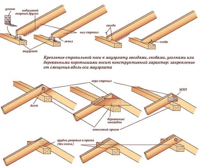
Figure 2. Attaching the rafter leg to the Mauerlat.
In other words, from the load created by building materials or atmospheric precipitation, the ends of the supports slide off, and the rafter system is damaged. This leads to its complete collapse. To prevent such an outcome, it is necessary to improve the reliability of these nodes. This is achieved using the following types of fastening:
- teeth in a tenon;
- teeth point-blank;
- emphasis on the end of the crossbar.
One or two teeth can be used depending on the slope. To increase the reliability of the connection, you can create additional fasteners using metal corners.
Roof lathing attachment points
The main attachment points for the rafter system are:
- beam;
- mauerlatny;
- ridge.
Beam attachment point

Figure 3. Diagram of the ridge connection of the rafter system.
In the rafter leg, teeth are created into a tenon, and a socket is cut in the crossbar, which corresponds to the cut teeth. In this case, the socket should occupy no more than 30% of the entire thickness of the crossbar.
If during the construction of the roof lightweight materials were used, and its slope is less than 35 °, the bases of the supports are placed so that the area of \u200b\u200btheir stop is much larger than the beam. This can be achieved by using a two-toothed 2-stud insert, a stop (with or without a stud), and two studs in the lock.
The system nodes are fastened either with hardware with metal corners, or wood blocks, linings and spikes.
Mauerlat mount
There are 2 technologies for Mauerlat support fastening: rigid and sliding (Fig. 1).
In the first case, a strong connection is established between the rafter and the Mauerlat without the possibility of slipping, bending and jumping out. This is achieved by placing special corners with a support bar. The formed knot must be fastened with a reliable wire using hardware. The nails are driven in at a certain angle from the side so that they are in a crossed state in the Mauerlat. The last nail is nailed vertically. This method is the most popular.
In the second case, the fastening is carried out using a special mechanism that allows a certain element (in this case, the rafter) to move in the desired direction (Figure 2).
To create such a connection, you will need to make a tie-in on the supports, and then lay them on the Mauerlat. As in the previous case, both parts of the knot are secured with two crossed nails and one vertical at the top. The boards are fixed to the Mauerlat with metal brackets. After that, the support base is released behind the wall and fastened using plates and sleds. Thus, the emphasis is on the Mauerlat, but all components of the rafter system can move within acceptable limits.
This method is most often used when erecting a roofing system of wooden buildings (logs, frame), which are characterized by subsidence. It is worth remembering that with a rigid mount there is a possibility of damage to the walls of the structure.
Ridge attachment point
Such a knot can be created in two ways: butt and overlap (Fig. 3).
The first method involves trimming the tops of the supports at the same slope as the corner of the roof. They are resting on opposite supports, which also need to be trimmed. The fastening is created using two nails (150 mm), hammered from above at a certain angle so that they are adequately positioned inside each rafter. To increase reliability, the seams between the supports are fastened with wooden plates or metal plates.
The second method is the most popular. It differs from the first method by the overlapping method. In this case, the supports are connected not by the ends, but by the side parts, after which they are fixed to the bolts.
The roof system is the part of the roof structure from the outside that is supported by supporting structure... It includes a crate and a rafter system. The triangle underlying this system should be rigid and most economical structural element, which contains the attachment points for the roof rafters.
The main characteristics of the nodes of the truss system
The main attachment points for the roof truss system are shown in Fig. 1. They imply the presence of a rafter leg (Mauerlat - 1), a rafter leg (ridge run - 2), a rack (tightening - 3). The structure of the rafter system is the main bearing element of the roof.
All roof attachment points must be of sufficient strength, this must exclude a significant degree of risk associated with roof collapse. The consequences of a mistake made when connecting elements can be the most unpredictable.

Figure 1. The main attachment points for the roof truss system: 1 - Mauerlat, 2 - ridge girder, 3 - tightening.
First, the rafters are installed on the Mauerlat if the building has brick walls... Similar nodes are provided for concrete blocks, then it is necessary to create a reinforced concrete stiffening belt, and studs must be inserted into its structure. Their location should be at a distance of 1 to 1.5 m from each other, and their diameter should be more than 14 mm. The top of the studs must be fitted with a special thread.
The Mauerlat is drilled, making the holes that are necessary to attach the elements to it. Each of the holes must be the same size as the stud diameter, and its pitch must match the distance between the studs. A nut is put on each protruding end of the stud and tightened, due to which the strength of the connection between the Mauerlat and the wall is ensured. The rafters should be connected to the Mauerlat so that they do not weaken bearing capacity.
Description of the main fasteners for mounting the rafter system
If in the process of building a house a rounded log or a bar was used, then it is not necessary to create an armored belt. produced on the upper beam or on the wall log. For this purpose, the connections of the Mauerlat with the rafters are used different ways cut (cut).
What fasteners are used to fasten metal rafters:
- Plates.
- Fasteners LK.
- Corners.
- Brackets WВ.
- Self-tapping screws.
- Varieties of the corner of the Kyrgyz Republic.
- Wire ties.
- Perforated mounting tape TM.
- By bolts with nuts.
- Brackets WВ.

If brackets are used when connecting the rafters to the Mauerlat, then they are not cut into the rafters, which helps to strengthen the bearing capacity. Usually, metal brackets are produced, and the metal is galvanized and has a thickness of 0.2 cm. Brackets are strengthened with nails, anchor bolts or screws.
The LK fastener can be used by creating attachment points not only for rafters with a Mauerlat, but also for other various elements that make up the roof structure. The LK fastener is anchored to wood, like the brackets, with the exception of the use of anchor types of bolts.
Mounting perforated tape allows you to strengthen the connecting nodes when erecting roofing systems. It is used not only to create stronger nodes, but also to strengthen elements for additional use in order to give rigidity or strength to the system as a whole. Fasten perforated mounting tape screws or nails, therefore it is used to strengthen the structure of the rafter system of any roof, the integrity of which will not be violated.

Using the corners of the KR and their various modifications, the attachment points are reinforced so that they can effectively participate in the connection of the Mauerlat and the rafters. Providing adequate strength to the nodes of the roof is permissible when using corners, which makes it possible to increase the load-bearing characteristics of the roof structure.
The use of metal connecting elements is not associated with cutting corners into the roofing system. This will not reduce the bearing capacity of the roofing system. You can use the corners for the connection using screws or nails, the protrusions of which resemble a ruff.
How are the knots connected in the ridge part?
There are three main types of fastening in the ridge parts of the roofing system:
- Butt joint.
- Fastening based on a ridge girder.
- The ridge joint is overlapped.
For the purpose of fastening, in the first way, the ridge part is cut off from the upper edge at an angle that is the same as the angle of the roof slope. Then it is resting against the necessary rafter, which must also be cut at an angle, but on the opposite side of the roof. A special template is sometimes used to trim the corners.
The nails for connecting the rafters under the ridge should be 150 mm in size or more, you will need two of them. Each nail is driven into the rafters at the top of the rafters at the appropriate angle. The sharp end of the nailed nail usually goes into the rafter cut from opposite sides. Strengthening the ridge joint can be achieved by applying a metal plate on the side or a wooden lining on it so that it is enough to tighten it with bolts or nails.

The connection in the second way, that is, through the ridge girder, is associated with the strengthening of the rafters on the ridge beam. A purlin is one of the additional support beams or beams, which is a support for the rafters. It is located parallel to the ridge or Mauerlat. The method differs from the previous one in that a ridge beam is laid between the rafters, which are cut at an angle, which is a laborious process, therefore this method is used less often.
A more common method is similar to the first, but it differs in that the fastening is overlapped, and the joint method is not used. At the same time, the rafters should touch the ends, and not the side surfaces. Tighten the rafters with a bolt or hairpin, nails. This connection is used by many masters in practice.
In general, it is possible to install rafters on a Mauerlat by creating structures of roof rafter systems that are spacer or non-spacer. This determines the choice of the appropriate method of connecting the Mauerlat and the rafters, which can be similarly strengthened to the ridge.
The main shortcomings when installing the attachment points of the rafter system
The problem of choosing the method of attaching the rafter system to the structure of the building is very important when creating attachment points. Often, when creating nodes, the Mauerlat serves as a support for the rafters. The Mauerlat bar is fastened “tightly” with anchor bolts to the reinforced stiffening belt.
A possible drawback is an unanchored stiffening belt, which can lead to the overturning of the Mauerlat beam and the violation of the stability of the roof truss system. The roof loosens and the roof slides down. The fastening is no longer effective due to incorrect placement of the anchor bolts or incorrectly drilled holes.
If the nuts are overtightened onto the bolts, the attachment point becomes fragile and undergoes rapid destruction. In this case, wire twisting is sometimes used to create a fastening point.
When building a rafter system, the safety of the connections must be observed.
For example, if the rafter structure is combined with the ceiling without taking into account the load-bearing capacity of the attic floor, then this is the most dangerous moment that can lead to the destruction of the building.

If the tightening is changed to a prefabricated reinforced concrete floor beam designed for bending, then the use of precast concrete beams should be effective due to their rigid attachment in a reinforced floor stiffening belt, which is arranged using a reinforcing cage. Its axis should go in the same direction as the acting forces.
At the same time, the presence of shortcomings in the process of creating a rafter system, which is a carrier wooden structure overlap, often arises due to a misunderstanding of the functions performed by the tightening and the crossbar in the entire roofing system. The tightening differs from the girder in that it is a longitudinal, and the girder is a transverse beam.
The construction of the rafter system is associated with the creation of a spacer system operating on the principle of divergence at the bottom of the planes, which occurs under the influence of not only their own weight, but also the load that falls on the line of intersection of the planes, which should be prevented by the cross beam, that is, tightening.
When starting to build a roof, you should find out all the points associated with making certain mistakes that arise when working on the construction of a rafter system. The device of the roof of the house is associated with possible difficulties and shortcomings that do not allow achieving the set goal.
The rafter system can be a spacer or non-spacer structure. From the right choice the nodes of support and articulation of the rafter legs depend on whether the rafters will expand the walls or not, it is necessary to provide for various measures for intercepting the expansion or not.
On the design diagrams, circles are drawn in the nodes of structures, meaning a hinge joint. The hinges are connected by paws with conventional supports, along which the degree of freedom of the node can be visually represented.
A hinge with two legs embedded in the support assumes that the node is stationary, but the beam can rotate in the hinge, that is, the node has one degree of freedom - rotation. A hinge with legs on a sliding support or slider shows that the node has two degrees of freedom - the ability to rotate the beam and horizontal displacement.
The knot's three degrees of freedom allow horizontal, vertical displacement and rotation; such a knot is simply drawn with a circle and can be cut into a bar that represents a beam. If the node is embedded in a beam, then it is called split, that is, the beams to the left and right of the hinge, with some assumptions, can be considered as separate elements.
If a circle (hinge) is drawn under a beam, then the beam lying on it is called continuous. A hinge with three degrees of freedom, embedded in a beam, in many cases makes it an instantly variable system, that is, a rather unstable structure. A node with a zero degree of freedom means rigid pinching of the end of the beam and prohibits it from any displacement: horizontal, vertical and rotation (Fig. 19).
Figure: 19. Examples of schematic representation of nodes
In the design schemes, other schematic images of nodes can also be used, but all of them are generally understandable, and if suddenly there are ambiguities, you just need to mentally imagine in which direction a node can "go" when a load is applied to it. The transverse dimensions of the beams with respect to their length are small, therefore, beams (rafters, etc.) are drawn as rods, and the load in them is distributed as if only along the longitudinal axis of the element and the calculation of the entire structure is carried out for the rod scheme.
It should be noted that the words: horizontal displacement and rotation do not mean at all that, for example, a slider - a node with two degrees of freedom moves arbitrarily in the horizontal direction.
In fact, this node is quite well fixed, but allows the end of the beam to move from load, temperature and humidity changes without excessive development of internal stresses in it. This node simply does not transmit the thrust, and the rotation during bending of the beam is possible only within the normative limits. In reality, the slider will creep (sorry for the tautology) only at loads exceeding the maximum permissible. The word "hinge" also does not need to be taken literally.
Yes, the ends of the beams can be connected with a bolt or a real specially designed hinge, but more often than not this is a normal nail connection. For example, you can take a board and nail it with one end with 3-4 nails, suppose to wooden wall... Nothing prevents us from taking it by the other end and calmly turning it at a certain angle.
In this case, the nail mount acts as a hinge. However, if the number of nails is increased and they are calculated for a load that does not allow shearing (bending), then rotation becomes impossible, here we get a beam with a clamped end, but when the load exceeds the calculated one, the node again becomes a hinge.
Therefore, it is very important to initially determine the load under which the system will operate. Since the excess of the actual load in excess of the calculated one, leads to a change in the operation scheme of the nodes and the destruction of the entire structure. Connections of layered rafters related to various schematic images of nodes are presented in Figure 20.

Figure: 20.1. Nodes for supporting the rafters on the girder and Mauerlat. Hinge with one degree of freedom (rotation only)

Figure: 20.2. Nodes for supporting the rafters on the girder and Mauerlat. Slider - a hinge with two degrees of freedom (rotation and shear)

Figure: 20.3. The node for supporting the rafters on the girder. Rigid pinching
Depending on the problem to be solved when designing a roof, the nodal joints of the rafters may be different from those shown in Figures 20. The main thing is to design in the nodes with two degrees of freedom: the turn arising from the bending of the rafters and the shift in the horizontal direction. And in nodes with one degree of freedom - the turn of the rafter. As a rule, the shift of the top or bottom of the rafters is provided by horizontal cuts, and the limitation of the shift is the support of the rafters against each other and / or into the abutting element: Mauerlat or purlin.
It is likely that people who are not associated with engineering professions, but who remember from the school physics course the principle of decomposing an inclined force vector into a horizontal and vertical axis, it is difficult to understand where the horizontal component in the lower part of the rafter leg goes. Let's try to explain the principle of a non-thrust system using an example. We can all easily imagine an ordinary ladder. The staircase is like a staircase, nothing special, two poles (bowstrings) and cross-step sticks.
Let us mentally attach such a ladder to the wall, and for the purity of the experiment we will pour oil on the floor and wall. What happens if you load a ladder - climb on it? The stairs will collapse. In the lower and upper support, it has two degrees of freedom. In the lower one it has a rotation and a horizontal offset, in the upper one - a rotation and a vertical offset.
What needs to be done to make the ladder stable in this oil-drenched environment and hold the load - the weight of a person? And you just need to deprive her of one (out of four) degrees of freedom: horizontal at the bottom or vertical at the top support. In other words, you need to secure the bottom or top of the stairs. When fixing the top of the stairs, the spacer from the decomposition of the inclined force acting along the longitudinal axis of the stairs remains at the top and acts on the wall, but at the bottom it is not.
If on the other side of the wall we put the same ladder and load it with the same weight, then we get a thrust in the upper part equal to the thrust from the first ladder, but directed in the opposite direction. These horizontal forces cancel each other out. We get a stable and stable system.
You can think of a mental experiment with a ladder in oil by putting it in different situations, for example, if the ladder is long and rests on the wall from above with bowstrings with horizontal gaps or without gaps. How will she behave?
It is quite interesting to carry out such a brainstorming session, which helps in understanding the work of layered rafters with various support methods, in which it is not at all necessary to imagine the vectors of forces and degrees of freedom of nodes, but simply to predict whether the staircase will roll along a horizontal plane or remain motionless due to the absence of a horizontal component of the force.
Mauerlat is one of the main elements of the roof structure. The rafters are attached to it. The operational period of the entire roof depends on the quality creation of the truss structure.
The main methods of supporting rafters
There are several technologies for supporting the rafters on the Mauerlat. The structure can be rigidly fixed. It does not allow any displacement of the rafter leg. To do this, you should use a hemming beam, due to which the rafters are prevented from slipping at the point of support, and metal corners, which eliminate any lateral shift of the structure.
The sliding joint of the rafter leg is used in wooden houses... Moreover, the main element for its emphasis is the upper crown, and not the Mauerlat. To prevent damage to the roof, the rafter support unit is made as free as possible. To do this, use a sliding support, which, when the log shrinks, is displaced along the guide fixed on the leg.
The sliding bearing unit can be made using a different technology. A gash is made in the rafters, which should adjoin the upper rim of the log house. For fixing the beams, it is permissible to use any fasteners: staples, nails or steel plates.
Fasteners for installation work

In order to qualitatively connect the rafters with the Mauerlat, you will need materials and tools such as:
- dry timber;
- boards;
- ax;
- hacksaw;
- hammer;
- roulette;
- plumb line;
- level;
- screwdriver;
- drill;
- bulgarian.
Particular attention should be paid to the availability of all fasteners. The fixation of the beams is done with galvanized steel beam brackets, which do not reduce the bearing capacity of the structure. There is no need to cut the brackets into the beams.
You also need to buy a perforated mounting tape that will strengthen the Mauerlat nodes. With its help, a strong connection of all structural elements is made. The tape also does not cut into the beams. For its reliable fixation, nails and self-tapping screws are used.
In addition to brackets and perforated tape, in order to securely support the rafters to the Mauerlat, you should purchase:
- universal bar connectors;
- fasteners for rafters;
- embedded supports;
- wire rod;
- steel corners;
- rack fasteners;
- self-tapping screws;
- nails;
- staples;
- plates;
- galvanized nails;
- studs with washers and nuts;
- anchor bolts.
Creating a ridge and installing the bottom of the rafters
Installation work begins with the ridge part of the roof structure. You can install the rafters in one of three ways:
- end-to-end;
- to run;
- overlap.
Butt joint construction involves cutting the upper part of the rafter leg. This is done at an angle that is equal to the slope of the roof slope. On the skate, a pair of legs are connected. To obtain the same node for supporting the Mauerlat elements, you should use a ready-made template.
A feature of fixing the rafters to the girder is the presence of a ridge beam. This option for arranging the Mauerlat is highly reliable. But often such a rafter support system provides for the installation of additional support structures, which will lead to a decrease in the functionality of the attic. Naturally, this method is not suitable for small roofs.

The technology for installing rafters with an overlap is in many ways similar to their installation on a ridge girder. The main difference is that the upper part of the legs is overlapped. This leads to a strong connection of the structure, since the studs hold two elements at once.
The connection of the lower ends of the rafters is carried out depending on the material of the walls. In the presence of wooden housing construction supporting element can act top rail walls. If foam blocks (or aerated concrete) were used during the construction of the house, then the rafters are supported on the Mauerlat.
Reinforced concrete belt device - optimal solution in the case of using masonry building materials... This technology does not provide for the creation of any methods of fixing the rafter system. Vertically located anchor bolts act as fasteners for the timber. The main thing is that when filling concrete mortar the studs were located in a strictly vertical position.
Connection of rafters with beams and Mauerlat
After fixing the top and bottom of the rafters, they should be fixed to the beams. It is clear that you can connect the rafters to the beam with just nails. But this is not the best solution. Such a mount will not be as reliable as possible. To prevent slipping of all elements, the fixing of the rafter structure to the beams takes place by using the “spike” and “tooth” connections.
If there is a steep roof slope (more than 35º), one-tooth cutting technology is used. At the bottom of the rafter, a tooth with a spike is made. Nests created in the beam should have a depth of 30% of the beam thickness. The device of rafter connections is carried out at a distance of 0.3-0.4 m from the extreme part of the beam. This prevents the beams from chipping due to the heavy load from the leg pressure.

When arranging a roof with a slope of up to 35º, the rafters are installed by expanding the interface area of \u200b\u200bthe main structural elements. Usually the rafter leg is covered with a beam. For this purpose, holes for two teeth are cut in the rafter leg:
- spike with emphasis;
- one more emphasis.
The depth of the cut when fixing the rafters to the beam is within 30% of the beam thickness.
Better connections can be obtained by using bolts or clamps. This technology involves the use of wire loops, with the help of which the knot is fixed to anchor boltslocated in the wall of the building.
Leaning on the Mauerlat is the most common option for securing the bottom of the rafters. A cutout of such a size is made in the rafter leg so that it can be put on the Mauerlat without problems. Otherwise, during the operation of the roof, the bar may move.
In some cases, the Mauerlat must be “equipped” with a reverse recess. It depends on the type of wood from which the bar is made. If hardwood was used for its production, a slot is made, which, in combination with the recess of the rafters, will create a locking element. When making a bar from coniferous tree a cutout is not required as it will weaken the structure.
The most acceptable option for a Mauerlat is a rigid coupling of the rafter system.

This technology can be done in one of two ways:
- using hemming bars and corners made of metal;
- by installing saddles on the rafters.
The first option is that a support bar is used to place the rafters on the Mauerlat. Rigid support of the rafter leg is made. Reliable fixation of the structure is carried out with metal corners. This prevents lateral movement of the structure.
The second option is more popular. For fasteners, nails are used that are directed towards each other and hammered at an angle. Two hammered nails are crossed. Then another nail is driven in. The third nail should be in an upright position. The fastening unit made will be characterized by maximum rigidity if additional fastening is carried out using a wire rod.


