- Connection diagram of a warm floor to a heating source
- Collector in the water underfloor heating system
- Preparatory operations for installing a warm floor
- Layout of pipes for a water-heated floor
- Varieties of laying patterns
- Preferred use of a spiral or zigzag
- The process of laying a water-heated floor
- Calculation of water floor heating
Installation of a water heating system on the floor of a room involves the calculation and design of the location of heating elements (pipes) inside the floor. A visual representation of the project in the form of a water floor heating scheme allows you to present the work heating system and mark the location of the circuit elements on the floor surface.
A warm water floor creates a comfortable environment, but its installation requires calculations and preliminary drawings of laying schemes.
The installation diagram of a warm floor is a drawing of the location of the water pipes that heat the room. Right choice the scheme determines the efficiency of the warm floor as heating. Exists general rules building a warm water floor system.
Connection diagram of a warm floor to a heating source

Figure 1. Wiring diagram for water heated floor.
The water entering the room is at the highest possible temperature. The heating temperature value is determined by the boiler output. When moving through pipes installed in the floor, the water gives off heat energy to the cement screed, which heats the interior of the room. With this heating scheme, the warm floor is a radiator.
The water leaving the room has a lower temperature, it enters the boiler for heating.
The water is circulated by an electric pump. In this heating system, the source of energy can be either an electric boiler or a gas, solid fuel or any other source of heating water in pipes. Therefore, a water heat-insulated floor is universal in the choice of a heating device and allows the replacement of one oven with another.
A pressure gauge is built into the system to control the water pressure. Its reading in normal operating mode should fluctuate between 1 and 3 bar.
To ensure a constant volume of water in the system, an expansion tank is provided. After the water is launched into the pipes, it is heated, accompanied by thermal expansion. The increase in volume is damped by a tank into which excess water is moved. In case of possible evaporation of water inside the system, the lack of heating liquid is replenished from the expansion tank (Fig. 1).
Back to the table of contents
Collector in the water underfloor heating system

Figure 2. With the help of taps installed on each pipe, the flow of hot water is regulated, and therefore the temperature.
In a schematic representation of a water floor, it is customary to designate hot water in red, and outgoing cooled water in blue. In each room of the heated room, a separate branch is laid - a loop that leaves the heating boiler and returns to it. The place of the warm water floor system, where one pipe is divided into several outlets corresponding to the number of heated rooms, is called a collector.
The location of the collector is determined by the interior of the utility room in which the boiler is located. Floor and wall placement of collector transitions is possible. Wall mounting of the collector is more user-friendly. Floor - does not create unnecessary pipe bends, therefore it is more functional for a water-heated floor.
A tap is installed on each pipe leaving the main hot pipe, which regulates the amount of incoming water. Controlling the amount of water allows you to adjust the temperature of heating the cement floor and the air inside rooms of different sizes.

Figure 3. Pipes from the collector are insulated before entering the heated room to reduce heat loss.
Hot water entering the pipe will heat up a small room more strongly and a larger room weaker. Therefore, for a small area, the collector tap at the inlet is slightly twisted, limiting the flow of hot water and reducing the speed of its movement in the system inside this room (Fig. 2).
Pipes laid to other rooms are insulated before entering their heated space in order to reduce heat loss and retain the maximum possible amount of heat energy for a particular room. The insulated elements are placed inside the cement screed together with other pipes that heat the room in which the underfloor heating boiler is installed (Fig. 3).
The entire pipeline of the water underfloor heating system is located on one horizontal plane. This ensures a freer and more uniform flow of water within the system.
Back to the table of contents
Preparatory operations for installing a warm floor
For the installation of a water-heated floor, a substrate is built of thermal insulation and (if necessary) waterproofing. It is convenient to attach the water pipes to the grid laid out over the insulation, which is a technological mounting device. The second mesh can be laid over the heating water pipe and serve as a reinforcing function if the floor is expected to be subjected to significant loads. Reinforcing mesh evenly distributes the pressure on the floor over the radiator floor area, preventing cracks.

Figure 4. Schemes of laying a water-heated floor
For the horizontal arrangement of pipes in the water underfloor heating system, before installing the insulation, an equalizing rough screed is performed, on which the insulation is then laid. Fluctuations in the height difference should not exceed 1 cm. Otherwise, the uniform flow of water will be disturbed and different heating of the interior will be observed.
A rough concrete screed in a private house can combine the functions of a heater and a primary support for a warm floor, if you add clay, tyrsu (sawdust) or foam crumbs to its composition.
The device of the water floor is carried out with metal-plastic pipes. This is the most popular material used for underfloor heating in modern construction. Other materials include cross-linked polyethylene (plastic polymer) and corrugated metal.
Back to the table of contents
Layout of pipes for a water-heated floor
Back to the table of contents
Varieties of laying patterns
The water floor can be installed in 2 ways:
- spiral or snail;
- zigzag or snake.

Laying the water floor in a spiral has the advantage of fewer pipe bends inside the room.
The pattern of the arrangement of pipes for a warm water floor is determined by the shape of the room, the location of the outer walls, the future location of large furniture, the purpose of the room (residential or utility, household).
The space along the outer walls requires more heating, therefore, if they are available in the room, the incoming pipe is directed to the outer wall and then its curls are placed in the direction interior walls... Such a water floor scheme is called “zigzag” or “snake” and is most often used in small rooms (in Fig. 4, image number 2).
The zigzag floor heating scheme can provide not only preferential, but also uniform heating of the room. For this, the bends are laid from a double pipe, as a result of which an alternation of incoming and outgoing (hot and cold) pipes in the circuit is obtained. This scheme is called the "double snake" (in Fig. 4, image number 3).
The spiral is always laid in a double pattern, in which a red hot stream alternates with a cold blue. Such a laying of a water-heated floor is used for large rooms (in Fig. 4, image number 1).
Back to the table of contents
Preferred use of a spiral or zigzag

Figure 5. Diagram of a spiral with decreasing step along one wall
The spiral has a big advantage due to fewer large bends. With smaller bends in the line, the water flows more freely inside the heating circuit. Sometimes a significant bend angle of the route does not make it possible to reduce the pitch between the pipes. With a zigzag installation of a warm floor, the minimum possible step is 200 mm, this may not be enough for a full-fledged heat supply to the room. The more frequent and tighter curves of the snake make it more time consuming to install.
Spiral laying allows pipes to be positioned 10 mm apart. At the same time, the process of laying warm water supply is easier, which is important if the work is performed by the owner's own hands, who does not possess special construction skills.
In most cases, a spiral scheme is chosen for the construction of a warm floor. A double snake is often designed for rooms of complex configuration, where there are additional structures installed on the floor that require a bypass of pipes. In such a room with a complex perimeter, it is often not possible to place a spiral around the entire perimeter.

Figure 6. Gradual unwinding of the coil from the end of the pipe is used when laying the floor in a spiral.
A single snake is used in small rooms with a clearly cold outside wall... Although in this case it is more expedient to perform thermal insulation outer wall.
It is possible to use the snake in the corner exterior rooms of the building. Then the incoming pipe is placed in several turns along the 2 outer walls, after which a snake is performed in the middle of the room.
Another option for enhancing floor heating locally, along the outer walls or windows, is to reduce the step (distance) between the streams in the required place. If the laying pattern is a spiral, then the incoming pipe is wound along the outer perimeter along the walls, and the step near the window and the outer wall is small (50-100) mm, and between similar turns inside the room is increased (150-200 mm) (Fig. 5).
The spiral method of laying is considered universal; it can be used in rooms of various perimeter shapes.
In this article, we will analyze what a water underfloor heating project is, why it is needed and when it needs to be performed. Let's consider what the scheme of a warm water floor looks like and the technology of laying a water heated floor. Here is a list necessary materials and list the equipment for a water heated floor.
Water heated floor. Project
A few words about when a project is desirable and when it is required. So, it is desirable (but not necessary) to make a project when a water-heated floor is an auxiliary (not the main) system, and when it occupies a small area (up to 15-20 m 2). If the water heat-insulated floor is the main heating system, or an auxiliary one, but larger in area than 20 m 2, the project must be done.
The main reasons why a project is needed:
- When installing a water underfloor heating system in a new building or in another case requiring official commissioning, the absence of a project may be the reason for refusal to commission. That is, if there was no initial project, it will still have to be done "retroactively" for the commissioning procedure.
- It is advisable to arrange the installation of a water-heated floor system by builders / installers with a work contract. A work contract with builders or contractors is concluded on the basis of a project that is mandatory part of such an agreement.
- Without a project, the time and cost of work will definitely increase due to the disorganized construction / installation process. In addition, according to experts, the cost of purchasing the system and its installation will amount to 30-60 € per 1 m 2. Thus, for a house with an underfloor heating area of \u200b\u200b100 m2, the costs will be 3000-6000 €. As we can see, the price of the equipment and installation of the system are commensurate with the cost of the entire structure. That is why you have to save on equipment, materials or work. It is possible to reduce the cost of materials only by performing an accurate heat engineering calculation, and on the basis of it, a system design. This will allow, on the one hand, to avoid unjustified overestimation of the heating power, and on the other hand, to provide comfortable conditions in the house. It is the project that allows you to save money on the purchase of equipment and at the same time not miss anything important.
The designer performs thermal calculations for your home. For thermal calculation of a house, you will need to provide the following information about the house:
- Floor plan of the house, where it is necessary to indicate the dimensions of windows, doors and external walls;
- Information about the material of the outer walls, and the types of windows and doors;
- Information about the required temperature in the rooms;
- The location of the boiler in the room and its height above the floor;
- Location of risers and bends inside the building;
- Information about rooms with PSO (with places of furniture installation and types of coverings).
Installation diagram of the water floor
The installation scheme for a water-heated floor must include (please note that these points are not overlooked by the designer and are agreed with you):
- Breakdown of the premises into sections (fields). Dividing the room into sections is a very important point, ignoring which will lead to the destruction of the screed. This is caused by its thermal expansion, for the compensation of which the division into fields is performed. The resulting number of plots will depend primarily on the area of \u200b\u200bthe room, as well as on its geometry. When breaking down, it should be assumed that the maximum field area should not exceed 40 m 2 with an aspect ratio of at least 1: 2. At the same time, U- and L-shaped rooms must be divided into fields, regardless of their area.
- Expansion seams. In order to avoid cracking of the screed, expansion joints should be provided along the borders of the fields obtained after breaking the room. In fact, these are the gaps between the screed sections of two adjoining fields or between the screed and the walls. The gap between the underfloor heating screed and the walls can be filled with EPS (2 cm), polyethylene foam, or damper tape. And in order to lay the pipe through the expansion joint, it must be placed in a protective rigid casing, the role of which is played by a corrugated tube with a length of 400 - 500 mm. It is also worth noting that only the supply and return lines of the circuit can pass through the expansion joint.
- It is necessary to coordinate the installation technology with the designers. The chosen method will determine what materials you can use for laying pipes. There are two technologies for installing a warm floor: "wet" and "dry".
- the required heating temperature of the pipes determines which top finishing (decorative) coating can be installed. For example, the maximum heating temperature of the parquet floor allowed by the manufacturer may be 25 ºС, which means that if the specified heating temperature for the water floor heating system is not enough to achieve the required heating level of the room, then you will have to either change the upper decorative floor covering, for example, to tiles, or install a wall heating system.
After finishing the design, you should have the following documents on hand:
1. Floor plan of the building heating system.
The plan should indicate the location of all system components:
- size and location of radiators;
- placement of pipes with indication of diameters and lengths of sections;
- a detailed diagram of pipe laying, indicating the step of laying a water-heated floor, the temperature of the coolant, the length and diameter of pipes for each circuit of the underfloor heating system;
- information on the required power for each room (radiator and floor heating).
- automation settings.
The figure shows an example of such a document:
Example wiring diagram
The drawing should show a diagram of the installation of a water-heated floor, indicating the thickness of the concrete screed, and the sequence of laying all components of the system.
2. In addition, you must be provided with full specification of equipment and materials for installation of systems, including everything that is indicated on the plan. An example of such a specification is presented below:

Sample specification
For the subsequent successful installation of the system, according to this specification, it must necessarily include the following components:
- Pipes for underfloor heating systems, pressure and temperature resistant, oxygen tight.
- Heat insulating material.
- Damper (edge \u200b\u200btape) or EPS strips.
- Set for expansion joints.
- Pipe fastening elements.
- A plasticizer added to concrete intended for floor pouring.
- Distributor with flow meters.
- Collector cabinet.
Additional questions that you need to know at the stage of designing a warm floor:
- options for laying pipes for a warm water floor,
- options for finishing coatings (over floors with a water floor heating system),
- liquids for water underfloor heating systems.
What will be the installation scheme, what kind of finishing coating, and what kind of liquid will be in the system, you need to decide not at the installation stage, but at the system design stage.
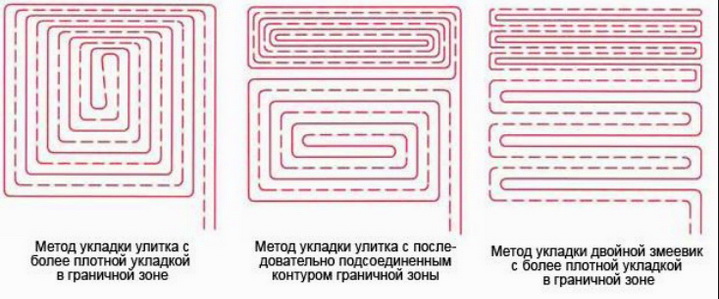
Options for laying pipes for a water-heated floor
There are two pipe-laying schemes: snake and spiral. All other schemes will be variations of either snake or spiral.

Snake pipe laying scheme

Pipe laying scheme with a spiral water floor

Spiral pipe laying with a boundary zone due to a separate heating circuit
- Snake installation is suitable for most small to medium sized rooms. Because the highest temperature will be at the initial section of the pipe, then laying should start from the side of the wall that has the greatest heat losses. This area against the wall is calledmarginal or boundary zone... In the edge zones, the laying step is reduced to compensate for heat losses. In most cases, pipes are laid with a pitch of no more than 300 mm, because at a greater distance between the pipes, the formation of a "temperature zebra" is possible. In the edge zone, the laying step is reduced to 200 mm, or even less (as far as the minimum bending radius of the pipe allows, and it depends on the pipe diameter).
- The snake contour gives an uneven heat distribution. To get rid of this phenomenon allows styling with a double snake or spiral. The supply and return pipe sections, with a spiral scheme, are laid in parallel, due to which the decrease in the return temperature is compensated by the high temperature of the adjacent supply. Coil installation is more suitable for rooms with large areas or high heat consumption. In addition, the spiral is recommended with a pitch of less than 200 mm, due to the limitation of the minimum bending radius of the pipe. For a pipe with a diameter of 20 mm, with a wall thickness of 2 mm, the minimum bending radius will be at least 100 mm.
- Please note that in the marginal zones, the step of laying the loops is reduced in order to compensate for heat loss. In this case, two types of edge zones are distinguished: integrated and separate. An integrated border zone is part of one hinge and is formed by decreasing the laying spacing at the outer walls, while the hinge spacing increases in the stay area. A separate boundary zone, as the name implies, is formed by a separate loop. If the length of the loop required for laying exceeds 100 m, then it is recommended to heat this area with several loops. This is especially true if there is a boundary zone. The reason for this is significant hydraulic losses in the circuit with a loop length of more than 100 m.
Top finishing (decorative) coating of a water-heated floor system
The upper floor covering is an important participant in the heat transfer process of the underfloor heating system. The coating material should be selected taking into account the thermal resistance of the coating.
- ceramic tiles (up to 30 mm thick),
- linoleum,
- laminate,
- parquet or wooden board (12-15 mm thick due to the low thermal conductivity of wood).
The greatest number of questions arise in the case of using a wooden coating. Wood is inherently hygroscopic. Underfloor heating typically results in some decrease in the relative humidity above the floor surface as the floor temperature rises. Relative humidity does not have the property of "self-leveling" - if in any zone (room) the temperature rises, relative humidity in this zone will decrease.
Important! Beech and Canadian maple are absolutely not suitable for systems with water underfloor heating. These types of wood change their geometric dimensions too much when the relative humidity changes. All other types of wood are suitable for use in water floor heating systems.
Laying of the wooden flooring must be carried out at an air temperature of + 20 ° C (± 2 ° C) and a relative air humidity between 30 and 60%.
The coatings approved by the manufacturers for use with underfloor heating are marked as follows:

Marking of finishing coatings for use with underfloor heating
When using any type of coating, it is important to limit the temperature of the heating medium supplied to the system so that the surface temperature under the finished coating does not exceed the temperature recommended by the coating manufacturer.
Fluids for water floor heating
Plain water, distilled water or antifreeze can be poured into the water floor heating system.
It is more advisable to use antifreeze in cases when the premises are heated irregularly during the cold season.
The use of antifreeze, and not water, in the water floor heating system should be considered when designing the system.
The warm floor is created according to certain schemes, which are available in the project documentation, or developed independently in accordance with the experience of construction in similar conditions.
In private houses, conditions differ little. It is important that the total heated floor area is similar (mainly 80 - 250 sq. M.) And the area of \u200b\u200bindividual rooms is 10 - 40 sq. M.
The equipment used in private houses is of the same type, and often the same - from the same manufacturer. This makes it possible to use similar constructive, installation schemes for warm floors.
Floor heating cake
The main constructive scheme is the "pie" of the warm floor. There is a certain sequence of layers. Here, the main difficulty is in preventing marriage and deviations from the accepted scheme.- 7. The base is horizontal and dry. height difference in the room - no more than 5 mm.
- 5. Leveling sand bed (fragile screed) for insulation.
- 4. Insulation - dense, strong and waterproof extruded polystyrene foam. Thickness - not less than the recommendations of SNiP on insulation (100 - 220 mm), for floor slabs - 35 mm.
- Waterproofing separates the screed from the insulation, prevents water from quickly leaving the screed.
- 3. Reinforcement - metal mesh 50 - 150 mm, from a rod of 4 - 5 mm, raised, so that it is in the thickness of the screed.
- 1. Pipeline - metal-plastic, PERT and PEX, usually 16 mm in diameter.
- 2. Screed concrete thickness from 8 cm, divided into fragments with a side of 4 - 5 m (one pipeline contour in a screed fragment).
- 8. Expansion joints filled with a damping tape 5 - 15 mm wide - divide the screed into fragments and separate from the walls
- 6. Floor covering suitable for underfloor heating.
- 9. The skirting board covers the expansion joint.

More detailed information on each layer can be found on this resource.
Visual layout of elements, - design, stacking sequence:

Laying the pipeline
The pipeline should be laid so that no temperature zebra occurs on the screed surface. Also, the packing density is determined by the required heat transfer in accordance with the heat engineering calculation (if any). The maximum distance between pipes is 250mm. The minimum is 100 mm.
The main laying scheme is a snail (spiral), in which the supply and return pipes alternate. Snake laying is best suited in rooms stretched along cold zones (corner), narrow and long.
Tighter installation (100 - 150 mm) in cold (edge) zones that run along the outer walls. The width of the marginal zone is usually 0.4 - 0.8 meters. Less density (150 - 250 mm) closer to the center of the building.

It is not recommended to make the length of one circuit more than 80 meters, so as not to exceed the pressure loss arising from the flow rate of the coolant, which covers the "average" heat loss of the building.
In other words, in order not to go beyond the technical capabilities of pumps 25-40, 25-60, when covering the heat loss of a "normal house".
The pipeline is tied to the mesh with plastic fasteners, -
Water floor scheme for home
The placement of the contours of the water floor in the house should be carried out in accordance with the project. The heat losses of the entire building and each room are taken into account, based on which the density of the pipeline laying, the speed of movement of the coolant, the pump, etc.But often it all comes down to the same type of schemes, with a contour length of 60 - 80 meters, which are applicable for well-insulated houses.
Or to the use of circuits with a length of 40 - 45 meters, for which simplified hydraulics with flow limiters are used -
Typical layout of contours. According to the calculation, not all rooms are densely packed in cold areas.

Approximately the same density of placement of contours over the area of \u200b\u200bthe house, - a laying step of 100 mm in the edge zone and 200 mm in the rest of normally insulated houses

Areas of the floor cluttered with equipment and low furniture remain without piping, for example, placing piping in a bathroom with a bathtub and shower stall.

Water floor connection, hydraulics device
The water floor is connected to the general heating network, just like the radiator branch, in parallel, through tees.
The wiring diagram of a water-heated floor is as follows:

It is necessary to pay attention to the means of protection. The diagram shows:
- A safety thermostat that turns off the pump and which is installed on the supply manifold.
- A bypass with a differential valve between supply and return, bypassing liquid when the pressure difference increases due to the closing of the circuits.
- Pump controller that turns it off when the servo drives on the manifold are closed.
We will analyze the work of the mixing unit and the collector separately.
How does a mixing unit with a manifold work
The diagram of the three-way valve operation is given. in which the supply from the boiler and the return from the warm floor are mixed.
The valve operation is possible only under the influence of a floor heating pump installed in the collector circuit (anywhere).

In practice, a two-way valve can be installed to shut off the supply to the mixing unit.
The valve is controlled by means of automation - a thermal head, the sensor of which is installed on the supply pipeline and regulates the temperature, usually within the range of 30-50 degrees. 
The collector of the water floor distributes the coolant to the circuits. Typically, balancing valves are installed on the manifold return manifold, possibly with servo drives. On the flow - flow indicators with the possibility of overlapping. But this is an expensive package.

The cheapest option for floor heating hydraulics for small house - a manifold with closing ball valves (with additionally installed balancing on the shortest loops), with a thermo-head of the mixing unit, which is manually adjusted.
According to the reviews of the specialists of the installation teams, almost all problems in the operation of water heated floors are associated with violations during the installation works... Moreover, the complexity is not only the laying process, but also the preparation stage.
Recently, professional installers were asked to tell you how to properly lay a warm water floor, check the build quality, as well as what the most common mistakes are made when assembling a heating system.
How to calculate the footage of a warm floor pipe
Before starting installation work, the total amount of consumable... This is due to the fact that the water circuit laid in the screed must be solid, without connections.The calculation of the pipe length for a water-heated floor is done as follows:
- The calculation of a pipe for 1 m² is carried out depending on the pitch between the spirals. If the distance between the loops of the loop is 10 cm, it will take about 10 rm. consumable material, 30 cm - 3.4 r.m. The pipe consumption for a water-heated floor remains unchanged for any method of installation. The difference in footage is influenced exclusively by the distance between the turns of the contour.
- The maximum number of meters in one water circuit is no more than 70 m. With a minimum step of 10 cm, 70 meters of the circuit is enough for installing a heating system of 7 m². Therefore, to warm up a room of 20 m², you will need to lay three separate circuits.
- The calculation of the number of pipes is also influenced by the future arrangement of the furniture. There is no need to lay floors in the place where the furniture will stand. The water circuit must not be laid close to walls and partitions. The minimum distance is at least 20 cm. To calculate the pipe, the dimensions of the indents must be subtracted from the total area. For a standard room of 20 m², this would be about 3.6 m².
The permissible distance between the pipes of a water-heated floor is from 10 to 30 cm. The choice of a step depends on the diameter of the pipe, climatic conditions and the intensity of operation of the heating system. So, if the floor is planned to be used as the main source of heat in the house, it is chosen minimum distance step.
Types of laying pipes for underfloor heating
There are several basic ways to install a warm water floor. The most simple circuit laying pipes for a water heated floor - "snail", allows you to perform independent installation, without the involvement of specialists. The low heat transfer and efficiency of the "snail" method somewhat reduces its popularity.There is also a type of styling - "snake". To implement correct installation snake is quite problematic and requires certain professional skills. But with the help of the snake laying option, it is possible to reduce heating costs.
Each of the installation methods has the following advantages and disadvantages:
Shell or snail
The floor is laid in a spiral pattern. In this case, it turns out that there is a return flow between the hot water supply pipes, in which the temperature is significantly lower. Correctly laying floor pipes with a snail is quite simple.The only drawback of the method is the appearance of cold zones with a large laying step, which must be taken into account when it is necessary to calculate the pipe. The best decision would be to take a step of no more than 10 cm.
Snake
Installation can be done with normal or double-lay piping. Correct laying of pipes for a water-heated floor with a snake avoids the appearance of cold zones or uneven heating of the air. To facilitate the installation process, there are special pipe mounting mats. By following the installation instructions, you can install the heating system yourself.To expand the pipe with a snake, special fixing elements are used. It is imperative that the contour is not firmly fixed. The pipe will expand and contract under the influence of hot water. It is important to avoid deformation of the water circuit after installation.
When choosing a laying method, one should take into account the total heated area of \u200b\u200bthe room, the availability of professional skills and the appropriate tool. Correctly connecting the hot water heating system is possible only strictly following the recommendations and installation steps indicated by the manufacturer.
Pipe-laying sequence
The most popular today is the concrete paving system. With this method, the pipeline after installation is filled with cement mortar with special plasticizers.The work is carried out as follows: 
Another effective method installation "polystyrene". In this case, the installation is carried out on heat-reflecting plates. The basis for laying the pipe is special mats with grooves and latches.
The polystyrene system has several main advantages: 
Full compliance with the rules for laying pipes with a snake or snail makes the independent installation of water-type heated floors problematic and almost impossible. The installation process will be facilitated by the use of special mats.
How to fix water floor pipes
When using a polystyrene board, the issue of fastening is solved due to the already existing grooves. The problem remains unresolved as to what to fix the pipes laid on the reinforced mesh. There are several options for this question:- Clamps are the cheapest way to lay the water circuit on a plastic or metal mesh. For fixing, clamps are most often used, which are usually used in electricians to tie wires.
- Clips - effectively replace the clips used in the polystyrene mounting method. The retaining clips provide enough space for the pipe to expand when heated. When installing, it must be remembered that the recommended diameter of the pipe bend is equal to its thickness multiplied by 8.
- Pipe-laying panels or fixing strips. The advantage of the panel fastening method is the possibility of quick installation work. The guides for fastening pipes are mounted according to a pre-drawn diagram. Fixation is carried out using latches, which makes the complexity of work easier and speeds up the installation process.
The choice of what to attach the pipes to is influenced by the chosen method of installation of the heating system and the size of the total heated area. For large rooms it is recommended to use installation panels and ready-made clips. In small rooms, you can do with clamps.
Do I need to crimp the water floor
As practice shows, this is necessary. It is necessary to pressurize pipes at least for the reason that the laying does not always take place in compliance with the necessary rules and regulations. So, often wanting to save money, the owners allow the installation of not a single circuit, but twists from several parts of the pipe. And, after the topcoat was laid and the heating system started up, it turns out that there are leaks.When pouring concrete into pipes, pressure testing is extremely important. Pipes under working pressure expand slightly and are filled in this state cement screed, do not exert pressure on the surrounding screed when the temperature of the coolant changes.
Crimping a water heated floor can be done by hand. The relatively small complications associated with the audit will fully pay off.
How to crimp a warm floor
Today, equipment for crimping is no longer a rarity. Moreover, if earlier only industrial installations were used for this purpose, now you can purchase a mechanical manual crimper.How is this procedure carried out?
- The hot water supply pipe is connected to the crimper. The return flow remains connected to the water manifold, on which the shut-off valve is closed.
- Pressure testing is carried out with air or water. With the help of the installation, the pressure in the water circuit rises. Practice shows that it is enough to create a pressure of 5-6 atm.
- The closed water circuit is left for a day with the device connected. This makes it possible to increase the pressure during pressure testing if necessary.
- A day later, the pressure in the system is checked with the previous indicators. During this time, there should be no changes in pressure.
The procedure for pressing the underfloor heating system includes checking each individual circuit connected to the manifold. In the presence of fistulas, localization can be found using a conventional stethoscope, or visually, by pressing with water.
The main tool for crimping pipes is a mechanical or electrical pump that creates the necessary pressure in the system and monitors the indicators using a pressure gauge.
Common mistakes when laying pipes
There are several common mistakes that both professional construction crews and novice installers make. These include:- Exceeding the maximum permissible pipe length. An excessive length of the circuit creates problems with the circulation of the coolant, the appearance of cold zones, an increase in energy consumption, etc. The maximum length should not exceed 70 m.
- Laying substitutes for damper tape or installing floors without using it. Often leads to condensation from above flooring, the appearance of cracks in the screed.
- Wrong choice of installation method. The layout of the warm water floor with a snail is optimal for self-laying, especially if the work will be carried out with the screed filling.
Calculator for calculating the number of radiator sectionsCalculator for calculating the footage of a pipe for a warm water floor
Calculation of heat loss and boiler performance
Calculation of the cost of heating depending on the type of fuel
Volume calculator expansion tank
Calculator for calculating heating PLEN and electric boiler
Heating costs by boiler and heat pump
Heat gun selection calculator
Air conditioner power selection
This article will focus on a water floor project. Here you will find answers to questions about why it is needed, and how to correctly implement it. The scheme of a water-heated floor is also detailed.
Features of drawing up a project
In some cases, its presence is desirable, while in others it is mandatory. It is better to have it if the warm floor is an auxiliary (that is, not the main) system. It is also advisable to make a project when it occupies a small area (up to 20 sq. M.). If this floor is the main heating system (or auxiliary), but affects a larger space, then drawing up a diagram is a prerequisite.
What is all this for?
When installing a system of such a floor in a new building, as well as in some other cases, official commissioning is required. If the project is not drawn up, then you can get a refusal. Thus, it is recommended that you take care of it well in advance. Otherwise, you will still have to start drawing up the project, only "retroactively". If we are talking about installing a water underfloor heating system with the hiring of professional builders, then it is best to resort to design It is based on the project. The latter is an obligatory part of the contract.
Price policy
If there is no project, then the cost and terms of work in any case increase significantly. The fact is that in such a situation, the process of installation or construction will be disorganized. According to experts, the purchase of the system and its installation requires up to 60 euros per 1 sq. m. Based on this, for a house with floor heating area up to 100 sq. m., you will have to spend up to 6 thousand euros. Thus, the installation of the system and the cost of the equipment are commensurate with the cost of the structure itself. In this case, you will have to start saving. This applies to the work performed, equipment and materials. It is possible to reduce the costs of the latter. This requires an accurate technical calculation. The scheme of a water-heated floor is drawn up on its basis. This eliminates an unjustified overestimation of the heating power. In addition, the guarantee of comfortable conditions in the house is guaranteed. The layout of the water heated floor allows you to take into account all important details, as well as save on the purchase of the necessary equipment. 
Features of technical calculation
As practice shows, the scheme is rarely drawn up. Certain knowledge is required for design. In addition, you need to have an idea of \u200b\u200bthe properties of various materials, the principle of operation of the heating system, as well as the norms and rules of installation. The diagram of the device of warm water floors must contain a technical calculation. Its implementation is carried out by the designer. In order for the thermal calculation of the house to be made, the following information must be provided to the specialists:
- Information about the PSO rooms (the type of coverage and the place of furniture installation are indicated).
- The location of bends and risers inside the structure.
- Information about the required temperature in rooms.
- Information about the material of the outer walls (the type of doors and windows is also indicated here).
- Boiler location and height above the floor.
- Floor plan of the house (the dimensions of the outer walls, doors and windows are indicated).
The installation scheme for warm water floors is based on a technical calculation.
Important information
The installation scheme for warm water floors includes many elements. It is worth paying attention to ensuring that important points are not overlooked by the designers and are coordinated with the owners of the house. 
Breakdown of premises into fields
The division into sections is a very important point. If you ignore it, then, most likely, the screed will collapse. It depends on its thermal expansion. The division into fields occurs just to compensate for it. The number of plots obtained depends on the geometry and area of \u200b\u200bthe room. Moreover, the maximum area of \u200b\u200bthe formed field is no more than 40 sq. m.
Expansion joints
They are provided along the boundaries of the fields, which are obtained after the division of the premises. This is done to prevent the screed from cracking. Basically, expansion joints are gaps. They can be filled with polyethylene foam or EPS. In order to carry out the laying of the pipe through it is placed in a protective rigid casing. The latter is a corrugated tube, the length of which is up to 500 mm. Please note that only the return or supply line of the circuit can pass through the expansion joint.
Installation technology
It is imperative to coordinate this moment with the designer. The selection of materials used for pipe laying will depend on the chosen method. Currently, the most common two technologies for installing underfloor heating: "dry" and "wet". The choice of top finishing coat depends on the required pipe heating temperature. For example, the maximum parameters allowed by the manufacturer are 25 degrees. The specified floor heating temperature may not be sufficient. In some cases, a change of the top decorative coating is required. Wall mounted heating system can be installed.
What should happen after the design is completed?
It is assumed that the owner will have a floor plan for the heating system. It should clearly reflect information about all components of the system:
- Automation setup parameters.
- Placement of pipes (length and diameter of sections are indicated).
- Information about the required power for each room (floor or radiator heating).
- Placement and dimensions of radiators.
- A complete pipe laying scheme (the diameter and length of each circuit of the system, the temperature of the coolant, the pitch of such a warm floor are indicated).
The drawing should reflect the complete diagram of the water-heated floor. The thickness of the concrete screed is also indicated here. The owner must be provided with all the information about the specifics of materials and equipment with the use of which the water heated floor will be installed. The installation scheme will allow you to avoid mistakes in the process of the work itself. 
Required tools and materials
In accordance with the information contained in the technical plan and connection diagram for a water heated floor, before starting work, you need to prepare:
- Distributor with flow meters.
- Collector cabinet.
- Plasticizer (added to concrete, intended for floor pouring).
- Fixing pipes.
- Complete set of expansion joint tools.
- EPS strips or damper tape.
- Heat insulating material.
- Special pipes that are designed for underfloor heating configurations (must be oxygen tight, temperature and pressure resistant).
A schematic diagram of a warm water floor collector should also be attached to the main plan.
Additional questions
At the design stage, you need to know the following:
- Variation of finishing coatings.
- Variations of pipe laying schemes.
- System fluids.
It will be too late to decide on this during the installation process. It is better to take care of this in advance at the initial design stage.
Warm floors water: wiring diagrams
The distribution of pipes along the base can be carried out different ways... Currently, two options are used: a spiral and a snake. Any other scheme for the device of warm water floors is a variation of one of the above.
Snake
This installation is suitable for most rooms that are medium to small in size. It should be noted that the initial pipe segment will have the most heat... For this reason, installation should start from the side of the wall that has the greatest heat loss. This area is called a border or edge zone. Here the laying step is reduced in order to be able to compensate for heat losses. Most often, the distance between pipes does not exceed 300 mm. The fact is that with a larger step, a "temperature zebra" can form. In the edge zone, the distance is reduced to 200 mm. It is acceptable if it is even less. In this case, the minimum bending radius of the pipe plays an important role. The serpentine circuit is characterized by uneven heat distribution. To get rid of this, you need to double styling. 
Spiral
Such a scheme of a water-heated floor assumes a parallel arrangement of the supply and return pipe sections. This compensates for the temperature drop. The spiral is great for rooms with high consumption or large areas. Such a connection scheme for a water-heated floor is recommended when the pitch is less than 200 mm. The reason lies in the limitation of the minimum bending radius of the structure.
Features of edge zones
It must be remembered that here the stitching step is reduced. This is done to compensate for heat loss. There are only two types of such zones: separate and integrated. The latter is included in one loop. Its formation occurs due to a decrease in the laying step at the outer walls. In this case, the distance must be increased in the stay area. The border area is formed using a separate loop. If the length of the latter is more than 100 m, then several similar elements will be required to heat this section. If there is a border zone, this option is most relevant. This is due to significant hydraulic losses in the circuit if the loop length exceeds 100 m.
Top Finish Coating Details
It is a very important participant in the heat transfer of the entire floor system. The coating material must be selected very carefully. In this case, it is worth paying attention to its thermal resistance. It is recommended to use the following:

Features of wood coating
In this case, a large number of questions may arise. Wood is a hygroscopic material. In most cases, the covering will slightly reduce the relative humidity of the air directly above the floor. This is due to the fact that the temperature of the latter increases. For relative humidity, "self-leveling" is unusual. If an increase in temperature occurs in a specific zone, then it will definitely decrease. Cannot be used for underfloor heating Also this applies to beech. With changes in relative humidity, the geometric dimensions of the indicated varieties of wood "jump" strongly. All others can be used in water floor heating systems. The recommended air temperature when laying wood flooring is +20 degrees. In this case, the relative humidity should be in the following range: 30% -60%. The use of any type of coating involves the mandatory limitation of the temperature that is supplied to the coolant systems. As a rule, all recommendations are found in the attached manufacturer's instructions. The scheme of a water heated floor with a thermostat involves the installation of equipment to maintain a constant temperature in the system.
Fluid information
Distilled or ordinary water, as well as antifreeze can be poured into the water underfloor heating system. The latter is best used when there is irregular heating of the room during cold periods. This should be reflected in the system design in advance.
Where is the best place to use?
As a rule, a water heating scheme is used in a private house. When installing the system in limited areas of the premises (bedroom, kitchen, bathroom), the easiest way is to use the electrical variation. This is due to the fact that in small space pipes are more difficult to position than cables. If such a heating system becomes the main one, then it is best to use a water type of construction. It should be noted that in a high-rise building with centralized heating it is forbidden to use a water heated floor. The system diagram from a separate circuit must be agreed with the relevant authorities. 
Layered construction
The scheme of the device of warm water floors is approximately the following:
- Thermal insulation (EPS or expanded polystyrene is used).
- or pasting.
- Main plate.
additional information
In a specific case, it is required to calculate the thickness of the thermal insulation that the water-heated floor will have. The diagram should contain this information as well. As for roll insulation with an aluminum surface, it is recommended to use variations with lavsan content. Thanks to him, the interaction of the concrete screed and aluminum will not occur. It is also worth noting that it is allowed to lay pipes directly on expanded polystyrene or EPS. Thus, the intermediate layer is skipped. It is necessary to pay attention to the pipes of a water-heated floor and a concrete screed with the addition of a plasticizer. This assumes the presence of a reinforced mesh with cells. The recommended wire diameter is up to 4 mm. The thickness of the screed of such a floor (taking into account the presence of pipes) is up to 10 cm. There are certain recommendations for the use of a plasticizer. It is believed that if you add it to the composition of the screed, then you can make it so that its thickness is 3 cm, while its reinforcement is optional. This opinion is not true. The use of a plasticizer does not eliminate the need to reinforce the screed. Moreover, its minimum thickness should reach 5 cm. In the case of using a plasticizer, it is put into the mixture in strict accordance with the attached instructions. Excessive amounts of it will cause the system to "burn out". Thus, cracks may appear. Reinforcing mesh must be placed above the pipes. This will distribute the operating load evenly. Nowadays, you can often find recommendations that supposedly the mesh can be placed directly above the pipes. However, in this case, the fulfillment of its constructive role is not possible. The fact is that it is convenient to attach pipes to the mesh. This is done with plastic clips. So, we can conclude that the presence of a mesh under the pipes does not obviate the need for its location directly above them. As for the finishing floor covering, this material must be marked on the possibility of its use in a floor heating device.


