Unfortunately, today many owners of brick houses (meaning unscrupulous operating companies and institutions) do not pay due attention to the issue of the need for mandatory scheduled inspections and repairs of the load-bearing walls of their buildings, despite the fact that their frequency and volume are clearly regulated in those operating on the territory RF regulatory documents. Often, the alarm begins to sound only after the collapse of structures. This happens either because of low qualifications of personnel, or stupidly in order to save money on periodic repairs. However, this savings in most cases ends with cost overruns.
Below, characteristic defects and damage to the bearing stone walls of buildings are clearly demonstrated, indicating their overload and beginning destruction. The presence of the defects shown in the photo indicates that the walls require immediate repair and reinforcement with preliminary (in some cases) measures for the temporary fastening of emergency sections of the walls in order to prevent their sudden collapse.
Photo # 1. Destruction and thawing of masonry outer wall to a depth of more than 40% of its thickness. There is a threat of sudden collapse.
 Photo # 2. A large through vertically oriented crack with an opening of 1-3 cm extending upward from the basement almost along the entire height of the wall. There is a vertical “rupture” of the walls, accompanied by vertical stratification of the masonry into separate independently working columns.
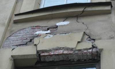 Photo # 3. Massive progressive through cracks between the window openings of the 2nd and 3rd floors. Cracks "fall" down, opening - "up". Displacement of horizontal rows and layering of masonry are observed. Pronounced signs of ongoing destruction of the bearing walls of the building: the masonry in this area does not work as a single structure, it is divided into many independently operating areas, each of which can collapse at any time. It is possible to restore this section of the wall only by re-laying it with a preliminary device of temporary fasteners.
 Photo # 4. The same house as in photo # 3. Such cracks can still be repaired. If this is not done, very soon there will be a picture on this section of the walls, similar to that shown in the photo above.
 Photo # 5. With such cracks (although “it” is already difficult to call a crack), a terrible accident can occur at any moment. And at first, the floors are likely to collapse. In this case, the reason for the formation of cracks is unambiguously the excess deformations of the bases and foundations. On the right side of the photo, traces of previous repairs are visible, during which an attempt was made to rid the house of cracks by tightening the defective walls with metal plates. It is not clear what the organizers of this repair hoped for. Indeed, in all the norms for the technical inspection and maintenance of buildings it is clearly stated that it is necessary to start repairing and strengthening stone walls damaged by cracks only after eliminating the causes of their appearance. In this case, these are unambiguously settlements or deformations of the base-foundation system.
 Photo # 6. A large through crack with an opening of 2-4 cm to the entire height of the wall, accompanied by vertical stratification of the masonry into separate independently working posts. In the area of \u200b\u200bthe crack, there was a noticeable buckling of the masonry and the deviation of the walls from the vertical, which indicates an overload and the beginning of the destruction of structures. Such a wall can still be "cured" if you start to do it immediately.
 Photo # 7. Large (through) vertically oriented crack with an opening of up to 6 cm, passing from the wall to the foundation. The reason for cracking is still the same - foundation settlements.
Well, that's probably all. In order to prevent the formation of the above defects and damages, it is necessary to immediately contact the experts when the first cracks appear on the walls.
Transcript
2 Grozdov V.T. Signs of an emergency state load-bearing structures buildings and structures. Foreword General provisions for assessing the accident rate of building structures Signs of an emergency state subgrade Signs of an emergency state of foundations Signs of an emergency state reinforced concrete structures Signs of an emergency state of stone structures Signs of an emergency state of structures of large-panel buildings Signs of an emergency state of steel structures Signs of an emergency state of wooden structures Conclusion
3 UDC Grozdov VT Signs of the emergency state of the bearing structures of buildings and structures. SPb, Publishing House KN +, p, 17 fig., 1 tab. Editorial Board DV Bernikov, AN Letchford, IP Yakovenko The signs by which it can be determined that the state of structures is emergency are considered. The term "accident" and the related concepts "emergency state" and "pre-emergency state" are formulated. The importance of knowledge by the engineering and technical personnel of construction and operating agencies of the signs of an emergency state of structures during the reconstruction and overhaul of buildings and structures is noted. The book can be useful for persons performing technical inspection of building structures and supervision of the construction and operation of buildings and structures. Reviewers V.M.Khomich Candidate of Technical Sciences, Professor (BITU), S. A. Platonov Corresponding Member of the MANEB, Candidate of Technical Sciences, Associate Professor (Department of St. Petersburg GASN) ISBN V. T. Grozdov,
if ($ this-\u003e show_pages_images && $ page_num doc ["images_node_id"]) (continue;) // $ snip \u003d Library :: get_smart_snippet ($ text, DocShare_Docs :: CHARS_LIMIT_PP_IMAGE_TITLE); $ snips \u003d Library :: get_text_chunks ($ text, 4); ?\u003e4 Foreword Structural failures of buildings and structures cause significant economic damage and are often accompanied by injury and death. Accidents of building structures usually occur due to a combination of reasons: errors in design, poor quality of materials used for supporting structures, violation of manufacturing technology and installation of building structures, non-observance of the rules for operating buildings and structures. Structural accidents rarely occur suddenly. A number of precursors of an accident can usually be observed. If you notice the signs of an approaching accident in time, you can take preventive measures in time: take people out of the danger zone, unload the emergency structure, install temporary fasteners, etc. Therefore, it is so important for the engineering and technical personnel of construction and operating organizations to know the signs of the emergency state of structures. The present work is devoted to this issue. 3
5 1. General provisions for assessing the accident rate of building structures The term "accident" and the related concepts "emergency state", "pre-emergency state" do not have a firm generally accepted interpretation. In this work, an accident of building structures of a building or structure means the collapse of a building structure or the entire building or structure as a whole, as well as the receipt by them of such deformations that make it impossible to operate them. An emergency state means such a state of the structure of a building or structure, in which, with a high degree of probability, its accident can be expected in the near future. A pre-emergency state is a state of a structure when, in the event of continued unfavorable influences (uneven settlement of the foundation, temperature drops, aggressiveness of the environment, etc.), a structural failure may occur. An accident of building structures is possible due to the presence of hidden defects in them, as a result of the fragile work of the structure, when the destruction occurs without preliminary strong deformations. In this case, it is very difficult to establish the existence of an emergency state of the structure. However, in most cases, structural failures are preceded by the development of large deformations, the appearance and opening of cracks and other visible signs of an emergency state. The purpose of this work is to describe the signs by which it can be determined that the state of the structure is emergency.Along with visual and visual-instrumental examination, verification calculations of the structure are usually performed to establish the accident rate of the structure. In verification calculations about the emergency state of the structure 4
6 judged by the degree of excess of the actual bearing capacity structure, taking into account the defects detected in it above the calculated one. In the existing design standards, the following provision is accepted: if any section of the structure has reached the first group of limit states, then this limit state occurs in the entire structure. With regard to the emergency state, this is true for statically determined systems. In statically undetectable systems, reaching the limiting state in any one section is usually not associated with the collapse of the structure. This should also be taken into account when deciding whether to recognize the state of the structure as emergency. Analysis of the survey results and verification calculations allows you to give a reliable answer to the question of whether the state of the structure is emergency. In this case, the following cases can be encountered: 1. inspection of structures reveals signs by which one can judge that the structure is in an emergency condition; the same is confirmed by verification calculations; 2. the survey reveals signs of an emergency state of the structure, but verification calculations do not confirm this; 3. The results of verification calculations indicate the presence of an emergency state of the structure, and examination of signs of such a state does not reveal. In the first case, no doubt, it should be considered that there is an emergency state of the structure. In the second case, verification calculations should be analyzed, namely: whether the influence of the identified defects in building structures was taken into account when performing them, whether the calculation scheme was correctly adopted. If no errors were made during verification calculations, then there is no sufficient reason to consider the state of structures as emergency. Depending on the type of construction and you- 5
7 revealed defects in some cases, such a state of structures can be recognized as pre-emergency. In the third case, it is necessary to inspect the structure again, and if there are no signs of an accident, then there will be no grounds for asserting the emergency state of the structure. Very often, there are cases when the breaking load significantly exceeds the bearing capacity of the structure, calculated according to the current standards. It should be noted that the correctness of the conclusion about the emergency state of the structure largely depends on the qualifications of the person making such a conclusion. In a number of manuals, instructions for the inspection of building structures, it is recommended that, when the bearing capacity of the structure is reduced by more than 50%, such a state of structures is considered to be emergency or even talk about their complete destruction. In this regard, it should be noted that the emergency state depends not only on the bearing capacity of the structure (the degree of reduction of the bearing capacity envisaged by the project), but also on the efforts caused by external influences. As for the collapse of the structure, it can also occur with a smaller decrease in its bearing capacity. If the structure has collapsed, then it has completely exhausted its actual bearing capacity. 6
8 2. Signs of the emergency state of the soil foundation The emergency state of the soil foundation is its state when the structures of a building or structure, resting on this foundation, are in an emergency condition due to unsatisfactory operation of the foundation. Consequently, the accident rate of the soil base is judged by the state of the structures resting on it. Design standards for foundations of buildings and structures limit the relative difference in settlement, average and maximum draft foundations. When the limit values \u200b\u200bof these deformations are exceeded in structures resting on the base, cracks should be expected. However, this does not always lead to an emergency state of buildings and structures. In many cases, only a violation of normal operating conditions occurs. The natural foundation, if natural disasters (earthquakes, landslides) are excluded, can come into an emergency state in cases when: - when designing a building or structure, the strength and deformation properties of the foundation soils are incorrectly estimated; - the technology of excavation works was violated; - freezing of heaving soils is allowed; - the rules for the operation of buildings and structures have been violated. As an example, when the violation of the natural structure of the soil foundation led to the emergency state of a part of the aboveground structures, one can cite the construction of a residential five-story large-panel building in the Leningrad Region. During the excavation of the pit, the main water pipe was damaged, and part of the pit, dug in loam, was flooded with water for a long time, which led to a strong waterlogging of the soil. After the 7
On the 9th day of the building, the soil bulged out from under the soles of the foundations with the destruction of the basement floor. Three sections of the house, built on liquefied soil, sagged and broke away from two previously erected sections. The cracks at the top of the building were 4 cm wide (Fig. 1). The reinforced belt, provided by the project due to the heterogeneity of the base, broke at the same time. In general, this building could not be recognized as emergency, since the deformations of the foundation stabilized and the building did not collapse. In this case, an emergency condition can be considered wall panels in the zone of cracks, since the connections of the panels with each other were broken and cracks appeared in the walls. Fig. 1. Deformation diagram of a large-panel residential building in case of strong uneven deformation of the soil base as a result of its soaking: 1 rocky soil; 2 loam; 3 damaged water pipe; 4 crack. An example of reaching an emergency state of aboveground structures as a result of freezing of heaving soils can be the deformation of the aboveground part of a two-story brick residential building during the construction period in Pushkin. The construction of the house was carried out in the winter. The basement windows were not glazed. Expanded clay gravel poured into the basement covered the foundations of the foundations near the outer walls.The inner longitudinal walls had a foundation that was recessed only 50 cm relative to the basement floor. Soil 8
10 under these walls froze, there was his heaving. As a result, the house split lengthwise into two parts. The crack width at the top of the end walls reached 8-10 cm. In this case, the house as a whole was not in an emergency condition. Only the condition of the longitudinal inner walls under the lintels could be considered emergency, since with the further development of heaving deformations, the possibility of collapse of the lintels and ceilings supported by them appeared. After restoring the stiffness of the walls in the summer by installing strands and sealing cracks, as well as warming the basement by next winter, there were no traces of the effects of frost heaving of the base. If the building were left with a basement not insulated by next winter, there would be a real danger of collapse of sections of the walls. During the reconstruction of a building, they often arrange operated technical basements instead of the previously existing semi-aisle subfields. In this case, the basement is usually deepened so that the distance between the basement sole and the basement floor surface is less than 50 cm, and sometimes the sole is even higher than the basement floor. In the latter case, an emergency condition of the subgrade always occurs. If the level of the basement floor approaches the level of the basement base at a distance of less than 50 cm, then it is necessary to calculate the base according to the bearing capacity (according to the first group of limit states), i.e. check the base for the possibility of soil bulging out from under the basement base. nine
11 3. Signs of an emergency condition of foundations An emergency condition of foundations occurs due to unsatisfactory operation of the subgrade or due to insufficient strength of the foundation body. In case of unsatisfactory operation of the soil base, through cracks form in the foundation, they are usually very open, rarely located, cross the foundation along the entire height and enter the walls. These cracks do not always lead to an emergency state of the aboveground structures. Cracks cause a redistribution of efforts along the length of the foundations, which can lead to overloading of individual sections of the foundations and their destruction. This is usually accompanied by local destruction of the foundation body at the lintels above the openings. In places of overload, weakly open, often located vertical cracks are formed and vertical stratification of the foundation body is observed. The latter is determined by tapping the vertical surfaces of the foundations. In places of delamination, the sound when tapped is dull. This state of the sections of the foundations should be considered emergency. With insufficient strength of the body of the foundations, often weakly open cracks appear in them and vertical stratification is observed. This is an emergency condition. The appearance of cracks in the walls of glass-type foundations for individual columns, the absence of proper solidification of the joint between the column and the foundation should be recognized as an emergency state of the foundation, since in this case the column embedding in the foundation envisaged by the project is not provided, which leads to an increase in efforts in individual frame elements. In the practice of the survey, the author encountered a case when, in a fully assembled two-story frame building, the columns were embedded in the foundation only with the help of temporary wooden 10
12 wedges, without grouting concrete. During the reconstruction of a building, when the basements are deepened, they do not always pay attention to the construction of the foundations. In houses built in past centuries, the lower part of the foundation was often made of rounded stones in a spacer with the walls of the trench without the use of a binder solution. At the same time, deepening the floor below the top of such masonry is unacceptable. During the reconstruction of a two-story house in the Leningrad Region, which had a similar foundation, instead of a semi-aisle underground, they decided to make an exploited basement. At the same time, a masonry of rounded stones was exposed to a great height. Stones began to fall out of the foundation masonry. The walls resting on this foundation received large deformations, the floors sagged, the partitions fell. Measures were not taken in time to strengthen the walls and foundations, sections of the walls began to collapse, and the building had to be completely dismantled. In this case, the very first stone that fell out of the foundation was a fairly reliable sign of the emergency state of the foundation. Several years passed from the moment the first stones fell to the collapse of the walls. 4. Signs of the emergency state of reinforced concrete structures In accordance with the provisions of the design standards for reinforced concrete structures, the ultimate state in strength occurs in the section of compressed, compressed-bent and bending reinforced concrete elements when the deformations in the most compressed fibers reach limiting values. This is considered a failure of the section of the element. In fully stretched sections, the limiting state occurs when the stress in the reinforcement reaches the design tensile strength of the reinforcement. In statically determined bending, eccentrically compressed and eccentrically tensioned elements at large 11
In eccentricities, the achievement of stresses in the tensile reinforcement of the values \u200b\u200bof the design resistances (physical or conditional yield strength) will inevitably lead to the destruction of the element section with a slight increase in the load. In statically undetectable elements, in this case, a plastic hinge will form, which will cause a redistribution of forces between the supporting and span sections of the element. Hence, it can be concluded that the appearance of fluidity in tensile reinforcement of statically determined elements is an emergency state (Fig. 2). In statically undetectable structures, the limiting state occurs when the compressed concrete zone begins to collapse (Fig. 3). The reaching of the tensile reinforcement to the yield point can be judged by the width of the crack opening at the reinforcement level. 12
Fig. 14 2. Scheme of cracks in a statically determined bending reinforced concrete element: 1 normal crack in which the reinforcement has reached the yield point; 2 oblique crack; 3 longitudinal crack in the compressed zone of the element. Figure: 3. Scheme of cracks in stretched and compressed zones in a statically undetectable bending reinforced concrete element: 1 normal cracks; 2 oblique cracks; 3 longitudinal cracks in the compressed zone of the element. If we neglect the tensile strength of concrete, then the crack opening will be equal to the absolute elongation of the reinforcement in the section between the cracks: (1) where e sm is the average value of the relative deformation of the reinforcement in the section between the cracks Here Ψs is the ratio of the average relative deformations in the section between the cracks to the relative deformations of the reinforcement in the section with crack e s. Roughly we can take Ψs \u003d 0.9. The relative deformations of the reinforcement when the yield point is reached can be taken for reinforcement having a physical yield point: from steel class A-I = 0,0011; (2) 13
15 steel class A-P \u003d 0.0019; of steel class A-Sh \u003d 0.0028. For reinforcement that does not have a physical yield point, the relative deformations when the conditional yield point is reached can be calculated by the formula (3) where σ sp2 is the stress in prestressed reinforcement at a stress in concrete equal to zero, taking into account all losses. For rough calculations, you can take: σ sp2 \u003d 0.6 * R s.ser. Then for reinforcement made of steel: class A-IV e s.pt \u003d 0.0032; class A-V e s.pt \u003d 0.0037; class B-II e s.pt \u003d 0.0048; class K-7 e s.pt \u003d 0.0037. With this approach to solving the problem, the opening of cracks corresponding to the achievement of the yield point in reinforcement can be represented in the form of the following table. Table 1 Crack opening a crc when the yield strength in reinforcement is reached, mm Thus, to judge whether the reinforcement has reached 14
16 rounds of the yield stress, you need to know not only the opening of cracks, but also the distance between them. Attention should be paid to the fact that at small distances between cracks, fluidity in reinforcement will be observed when cracks open significantly less than provided by the Standards from the condition of reinforcement safety from corrosion. When clarifying the issue of reaching the yield strength in transverse reinforcement (transverse rebars, clamps), given that inclined cracks are usually located at an angle of 45 to the element axis, the crack opening value in Table 1 should be multiplied by a factor of 0.7. In this case, the distance between the cracks should be taken as the perpendicular distance to the element axis between two adjacent cracks or (if there is only one crack) the length of the transverse bar. The achievement of ultimate deformations in the compressed zone of concrete is judged by the appearance of cracks parallel to the axis of the element (Figs. 2 and 3), and delamination in this zone of flakes. If an oblique crack at the free support of the element reaches the stretched face and the crack opening exceeds 0.5 mm, this indicates that the longitudinal reinforcement on the support has been pulled. If longitudinal cracks appeared in concrete over the end of an inclined crack at the same time, then an emergency state of the structure occurred due to its destruction along the inclined section (Fig. 4). Figure: 4. Scheme of destruction of a reinforced concrete element along an inclined section due to pulling the reinforcement on a free support: 1 longitudinal cracks in the compressed zone of the element; 2 oblique crack; 3 longitudinal stretched reinforcement; 4 transverse reinforcement. fifteen
17 Cracks in concrete along longitudinal tensile reinforcement can form for the following reasons: - corrosion of reinforcement, accompanied by an increase in its diameter; - straightening of reinforcing bars, initially having a bend; - pulling reinforcement on a free support. In all three cases, the adhesion of the reinforcement to the concrete is disrupted, which increases the deformability of the element and reduces its bearing capacity. The emergency state of the element can be said if the opening of normal and inclined cracks exceeds those indicated in Table 1 and there are longitudinal cracks with the formation of flakes in the compressed zone of concrete. In case of corrosion of high-strength reinforcement in prestressed reinforced concrete structures, there is a danger of sudden brittle destruction of the structure due to breakage of the reinforcement. Therefore, the presence of corrosion of high-strength reinforcement is a sign of an emergency state of the structure. Longitudinal cracks along the compressed reinforcement indicate that either corrosion of the reinforcement has occurred, or its rods have begun to lose stability due to the excessively large distance between the transverse reinforcement (Fig. 5). In both cases, there is a decrease in the bearing capacity of the element not only due to changes in the forces perceived by the compressed reinforcement, but also due to a decrease in the compressed zone of concrete. This condition is emergency. Figure: 5. Scheme of destruction in the compressed zone of concrete with loss of stability by compressed reinforcement bars: 1 longitudinal compressed reinforcement; 2 transverse reinforcement. sixteen
18 The presence of cracks in the column console is usually a sign of a large overload of the console and threatens the collapse of the structure resting on it. Therefore, a column with cracks in the consoles is emergency. The deviation of the column from the vertical, allowed during the installation process, does not always serve as an indicator of its unsatisfactory performance. With a reliable connection of the deflected column with overlappings and good homogenization of the latter, its deformation in the horizontal direction is possible only with deformation of the entire temperature-shrinkage block, i.e., additional force from the tilt of the column will be distributed between all columns of the temperature-shrinkage block. If the deviation of the column from the vertical occurred during the operation of the building and is accompanied by uneven settlement of the foundations, then this may indicate the approach of a building accident and requires an immediate assessment of the state of all structures adjacent to the deflected column. Violation of the integrity of the joints of the mating elements is a sign of the emergency state of the deflected structure and the elements resting on it. During the operation of a building or structure, reinforced concrete structures can receive various damage. Most often, damage is of a mechanical or physicochemical nature. As a result of mechanical shocks on the surface of the structure, local damage to concrete and reinforcement can occur. Concrete chips are most dangerous in the compressed zone of the element. In case of impact, damage to the reinforcement is possible in the form of its deformation or a decrease in the size of the cross-section. If, upon impact, a curvature of the reinforcing bar with delamination of the protective layer is formed, then the limiting force that can be absorbed by the deforming bar decreases. In a stretched bar, the ultimate force can be calculated by the formula: 17
19 where δ l is the relative value of the limiting force in the rod, taking into account the presence of curvature, which can be determined from the graph in Fig. 6 depending on the relative value of the curvature arrow lo / d; r is the radius of the cross section of the curved bar. (4) Fig. 6. Dependence of the relative force δ 1 \u003d 4N / Rsnd2 in the bar on the relative eccentricity lo / d In a compressed bar with the loss of its connection with concrete, the limiting force can be calculated as in a steel eccentrically compressed element using the formula: where φ is the coefficient determined from table 74 depending on the reduced relative eccentricity m ef and conditional flexibility λ. The value of m ef is calculated by the formula: where h is the section shape factor, which can be taken equal to 1; m relative eccentricity, op- (5) (6) 18
20 reduced by the formula: Conditional flexibility l is calculated by the formula: where s is the spacing of the transverse reinforcement. (7) (8) Fig. 7. Dependence of the degree of decrease in the strength of the reinforcing bar δ2 on the relative depth of damage h 1 / d. If, upon impact, damage to the reinforcing bar was formed, which led to a decrease in the size of its cross-section without losing the connection between the reinforcement and concrete, then the limiting value in the damaged stretched or compressed bar can be calculated by the formula: where δ2 is the coefficient characterizing the degree of decrease in the strength of the damaged reinforcing bar, the value can be determined from the graph in Fig. 7, depending on the relative depth of damage to the rod (9) 19
21 h l / d; gs coefficient that takes into account the stress concentration at the point of damage to the bar (10) If the reinforcing bar upon impact received simultaneously both curvature with the loss of connection with concrete and a defect in the form of a decrease in the cross-sectional size in the plane perpendicular to the bending plane, then in a stretched bar the limiting force can be determine from expression (11) In a compressed rod, in this case, the force Nsu decreases depending on the curvature arrow and the depth of damage to the rod. The approximate value of Nsu for a compressed bar can be obtained from the expression (12) Having calculated the bearing capacity of the element taking into account the ultimate design force in the damaged reinforcing bar, comparing it with the design force in the element and taking into account the presence and nature of cracks in concrete, a decision is made on the possibility of recognizing the structure as emergency ... Experiments carried out at VITU by OB Kerzhentsev showed that in the presence of one-sided damage to stretched reinforcement, the destruction of reinforced concrete elements occurs with a rupture of the damaged reinforcement with relatively small deformations of the elements. Hence, the conclusion follows: one-sided damage to the tensioned reinforcement indicates the emergency state of the reinforced concrete structure. When exposed to an aggressive environment, concrete strength changes, its local destruction, and reinforcement corrosion. 20
22 If, when reinforced concrete structures are damaged, the above-mentioned signs appear, indicating their large overload (cracks, delamination of the flakes in the compressed zone of the elements, etc.), then the damaged structures should be considered as emergency. In some technical literature, a relative deflection of conventional bending reinforced concrete elements is suggested that exceeds 1 / 150 span, be considered a sign of the emergency state of the structure. In other sources, for example, in the Recommendations, the emergency state of a structure is proposed to be considered with a relative deflection greater than or equal to 1/50. However, the large deflection of reinforced concrete elements in itself indicates only their low bending stiffness. The proximity to the emergency state of bent reinforced concrete elements can be judged by the values \u200b\u200bof the relative deflection corresponding to the achievement of the ultimate state in strength, which is determined by the formula (13) where δ is a coefficient depending on design scheme bending element; Mi is the limiting bending moment that the normal section of the element can take when the limiting state of the first group is reached; B flexural stiffness of the element. For a rectangular section with single reinforcement (14) where μ is the reinforcement coefficient (15) 21
23 With short-term loading, the value of B can be calculated by the formula (16) and with prolonged exposure to the load and relative humidity air W 40% (17) After substituting (14) and (16) into equation (13) we obtain (18) and after substituting (14) and (17) into equation (13) we have (19) Since the deflection of the bent elements is counted from the rectilinear axis of the element, then in prestressed beams from the value of the relative deflection calculated by the formula (18), the relative deflection from the short-term action of the pre-compression force P, calculated by the formula (20), should be subtracted and from the value of the relative deflection calculated by the formula ( 19), subtract the additional relative deflection from shrinkage and creep of concrete, determined from the expression (21) where εb and εb are the relative deformations of concrete from shrinkage and creep at the level of tension 22
24 reinforcement and the most compressed face of the section, calculated according to the Norms. If the relative deflection of an element exceeds the values \u200b\u200bcalculated by formulas (18) and (19), but cracks in the tensioned zone are not more open than those given in Table 1, and there are no signs of destruction of the compressed zone, then the state of the structure should be considered a pre-emergency state. When cracks open in the tensile zone more than those given in Table 1 and there are signs of the beginning of destruction of the compressed zone of concrete, the state of the structure should be considered emergency. In fig. 8 shows the dependence of the relative deflection f / l of reinforced concrete bending elements on the ratio of the span l to the working height of the section h 0 when the first group of limiting states in normal sections is reached for rectangular beams made of concrete of class B20 with reinforcement made of steel of class A-III and μ \u003d 0.015 ... Figure: 8. Dependence of the relative bending f / l of a reinforced concrete bending element on the ratio of the span l to the working height of the section hо for concrete class B20, class fittings А-Ш and p. \u003d 0.015: 1 for a single-span freely supported beam and short-term load; 2 the same for long-term loading; 3 for cantilever and short-term loading. Fig. 8 it can be seen that the achievement of the limiting state of the first group in a normal section can occur at values \u200b\u200bof relative deflections that differ markedly
25 from 1/150 both in one direction and in the other direction. Thus, to use the criterion of the relative deflection of reinforced concrete structures when establishing their emergency state, each time the value of the relative deflection should be calculated based on specific conditions (span and diagram of a bending element, classes of concrete and reinforcement, reinforcement coefficient). In some cases, when there are no visible signs of overloading reinforced concrete structures, they may be in a pre-emergency state. This happens when the stability of the structure is not ensured. These include omissions or poor-quality execution of vertical ties, absence or non-design welding of embedded parts. In these cases, even with a slight increase in loads, structures can collapse. Recently, cases of collapse of balconies and canopies have become more frequent. If the balcony slab or canopy is reinforced concrete, then the signs of their emergency state are associated with defects in both the stretched reinforcement and the compressed zone of concrete. In case of unsatisfactory condition or lack of waterproofing of balcony slabs and canopies, as a result of repeated exposure to atmospheric precipitation and temperature drops, the upper and lower zones of the slabs are destroyed, which causes corrosion of reinforcement and concrete. In case of corrosion damage of reinforcing bars by more than 30%, the condition of the slabs of the balconies and canopies should be considered emergency. With insufficient concrete density, moistening it due to poor waterproofing of the slab and alternating freezing and thawing, the lower surface of the slab rapidly collapses. This reduces the working height of the slab section. The destruction of more than 30% along the concrete depth of the slab is a sign of its emergency condition. 24
26 5. Signs of the emergency state of masonry structures A large overload of masonry elements can be judged by the presence of cracks in them. Cracks can be visible, emerging on the surface of the masonry, and invisible internal delamination. However, not all cracks in the masonry indicate overload. Cracks in masonry can also appear as a result of uneven settlement of foundations and temperature effects. In case of uneven settlement of foundations and temperature effects, as a result of redistribution of efforts between the elements of the masonry, an overload of individual elements can occur with the formation of cracks of force origin in them. The onset of the emergency state of the masonry in connection with its overload corresponds to the third stage of the stress-strain state of the masonry. This stage is characterized by the appearance of frequently spaced vertical cracks with a small opening and passing through the vertical seams of the masonry and several rows of stone (Fig. 9). Figure: 9 Diagram of the third stage of the stress-strain state of masonry. 25
27 Cracks extending to the outer surface of a stone element are usually accompanied by internal delamination of the masonry. This can be set by tapping the stone element. If there is an internal stratification, then a dull sound is heard when it hits the surface of the masonry. As the builders say, the masonry "bays" at the same time. Internal layering of masonry often leads to bulging of the outer masonry masonry. Recommendations suggest that a deviation from the vertical of a masonry element by more than 1/3 of the element's section height should be considered unacceptable. When taking these recommendations into account, it should be borne in mind that if a deviation from the vertical is allowed during masonry, then the horizontal component of the force arising from this deviation will be extinguished by the connection of the deflected element with other sections of the masonry and floors. With such a deviation from the vertical of the stone element, it should be calculated taking into account the connection with the adjacent masonry elements and ceilings. If the calculation shows a satisfactory state of the masonry, then there will be no reason to consider such an element as emergency. If the sections of the wall or pillar deviate from the vertical with their separation from the adjacent wall elements caused by uneven settlement of the foundations, in the case when the settlement has not stabilized, there is a danger of collapse of the breakaway elements of the masonry. This should be considered an emergency condition of the masonry. Dangerous is the appearance of cracks in the masonry under the ends of beams, girders, lintels of large spans or under support pillows (Fig. 10). In this case, the possibility of collapse of the element resting on the masonry arises. This is the emergency state of the element. In case of insufficient support of the floor slabs on the walls, a chipping of the masonry under the end of the slab can occur, as well as the pulling of the slab reinforcement on the support. In the absence of visible signs of destruction of the masonry under the end of the slab and 26
28 oblique cracks in the slab, the condition of the slab should be considered pre-emergency. If the load on the slab increases, it may collapse. Figure: 10. Diagram of the destruction of masonry under the support cushion. 1 beam; 2 support cushion; 3 oblique crack. Cracks in the masonry caused by uneven settlement of foundations, temperature effects, as well as the lack of dressings of longitudinal and transverse walls lead to a decrease in the spatial rigidity of the building. This is the pre-emergency state of the building. Structural collapse can occur in the event of significant horizontal forces. Therefore, the spatial rigidity of the building must always be restored. There are known cases of the collapse of detached brick walls, not fixed by ceilings and walls in a perpendicular direction, from the action of a wind load. This can happen when the technology for erecting new walls or disassembling old ones is violated. A freestanding wall can be considered emergency if its height is greater than that determined by the formula (22) where h is the wall thickness; γf load safety factor equal to 0.9; ρ is the density of the masonry; g acceleration of gravity; c is the aerodynamic coefficient adopted according to the Standards; w high-speed head, take 27
29 passed by the Norms; y is a wind load safety factor. 28
30 6. Signs of emergency state of structures of large-panel buildings Foundations, floors, staircases of large-panel buildings have the same signs of emergency state as similar structures of other buildings. Wall panels and joints of wall panels with each other and with floor slabs have specific signs of an emergency state. The collapse of a large-panel building can occur as a result of a large uneven settlement of the foundations, which led to a violation of the integrity of individual panels and their interfaces. It is also possible for a large-panel building to fail due to the destruction of individual load-bearing panels with insufficient bearing capacity or due to the poor quality of horizontal joints. With a high-quality implementation of the nodes of interface of wall panels with each other and with floor slabs, the destruction of one wall panel should not lead to a progressive collapse of the entire building or all structures located above. This is ensured by a special design of the joints of the elements of large-panel buildings that allow large plastic deformations. It is possible to control the quality of the connection nodes only during the construction and installation work or when opening the nodes of the erected building. However, in the latter case, significant damage is caused to the integrity of structures, their appearance, and at the time of opening the units and their subsequent repair, the operation of the premises becomes difficult. It should be borne in mind that connections at the nodes of connection of the elements of large-panel buildings with each other must be carried out strictly according to the project. Both decreasing and increasing the cross-section of the bonds will have negative consequences. With a decrease in the cross-section of the bond, there will be insufficient strength of the connection, and with an increase in the cross-section, there will be
31 children reduce the plastic deformation of the bond. Individual curtain wall panels can fall out of the wall due to broken ties. The forerunner of this is the exit of the panel from the plane of the wall, the appearance of rusty spots at the locations of steel ties and cracks in horizontal and vertical seams along the perimeter of the panel. If hinged panels are attached to the frame, then the gaps, even significant, between the panel and the frame cannot serve as a basis for recognizing the panel as emergency. In most cases, the presence of a large gap between some wall panels and columns of the frame indicates a careless installation of the frame, that is, that the columns are not mounted in the same plane. In this case, you should check the position of the questionable panel relative to the outer surface of the wall. If the panel does not protrude outward relative to the outer side of the wall, then its condition should be considered satisfactory. Vertical and horizontal cracks in wall panels increase their permeability. Horizontal cracks also reduce the stiffness of the panel from its plane. Figure: 11. Scheme of inclined cracks in a wall panel: a in a panel without an opening; b in a panel with an opening; 1 crack. The presence of inclined cracks is dangerous (Fig. 11), since along the crack, the panel parts may shift with their subsequent destruction. A sign of possible destruction is the appearance of cracks and peeled flakes at the horizontal joints between the panels, which is evidenced by
32 indicates a large heterogeneity of the mortar bed in this seam. Peeling and loss of the outer protective layer cannot be a sign of the emergency state of the wall panel. When the outer protective layer is destroyed, there is a danger of wetting the wall with rain and reducing its thermal properties. 31
33 7. Signs of an emergency state of steel structures When such defects in steel structures are found, such as general and local bending of a steel element, local weakening of the section, corrosion of steel, in order to determine the state of the steel element, it is necessary to perform strength calculations taking into account the identified defects. The methodology for these calculations is described in the Handbook. However, in some cases, even without performing verification calculations, it can be concluded that there is an emergency state of steel structures. Cracks in welds, in the near-weld zone, transverse cracks in stretched elements, as well as cracks coming from riveted holes, is an indisputable sign of an emergency state of structures. Often the cause of steel structures failures is the loss of local stability at the interfaces. In fig. 12, a shows schemes for the formation of local bulging of the welded I-beam wall in conjunction with the frame post with the crossbar. In the places of the fracture of the welded I-beam belt, due to the concentration of stresses in the thin wall, a local loss of wall stability occurred, which led to the collapse of the frames of the sports facility. A similar phenomenon occurred in the steel frames of the warehouse building (Fig. 12, b). This accident would not have happened if stiffeners were installed in the places of the belt fracture. In Leningrad, an accident occurred in the structural covering of a sports facility from steel pipes and shaped rolled products. The cause of the accident was the loss of stability of the gusset at the upper chord of the structure due to the large distance between the lattice element and the upper chord (Fig. 12, c). During the installation of the structure, the gusset was bent, which aggravated its complex stress state. 32
34 Fig. 12. Diagram of the junction nodes of steel structure elements that led to accidents: a crossbar and columns of a sports building; used crossbars and columns of the warehouse building; in the brace to the horizontal upper elements of the structural covering; 1 concentration of force acting on the wall of I-section elements, 2 design stiffeners; 3 stiffening ribs providing local stability of the element walls; 4 tubular braces; 5 upper horizontal structural cover elements; 6 the lower edge of the gusset according to the KM project; l Large free gusset length. Hence, we can conclude that any local deformation in the joints of steel elements is a sign of an emergency state of the structure. Sometimes, when constructing internal walls and partitions, they cross the structures of floors and coverings without leaving the necessary gaps at their intersections (Fig. 13). 33
35 Fig. 13. Diagram of the intersection of the truss with the partition and the correct solution of the intersection, in the wrong solution of the intersection, 1 floor slab, 2 chords of the truss, 3 the partition, 4 holes in the partition where it intersects with the chords of the truss, filled with elastic material, 5 the gap between the partition and If the walls or partitions rest on foundations that are not connected with the foundations of the supporting structures, on which the structures of floors and coverings are supported, then with a difference in the settlement of the foundations, either the walls (partitions) hang on the structures of the floors (coverings), or the latter rest on these walls and work in off-design mode. This can lead to failure of floor and roof structures. As in the case of reinforced concrete bending elements, it is impossible to judge the emergency state of steel beams only by any fixed value of the relative deflection. The span and section height of the beam must also be taken into account. When fixing the upper belt from displacement in the horizontal plane, the limiting force that the normal section of the beam can take is expressed by the formula 34
36 Mu \u003d R y g with W, (23) where g is the coefficient of the conditional work of the beam. Figure: 14. Dependence of the relative deflection of a steel beam on the ratio of the span l to the height of the section h when the normal section reaches the ultimate strength: 1 for a single-span freely supported beam; 2 for cantilever beam. The value of the relative deflection in this case, taking into account the formula (13), is determined by the formula (24) In Fig. 14 shows the dependence of the relative deflection of a steel beam when the limiting state of the normal section in strength is reached on the value of the ratio of the span l to the height of the section of the beam h with the initial data R at γ c \u003d 200 MPa and E \u003d 2 * 10 5 MPa. As well as for a reinforced concrete bending element, there are large fluctuations in the values \u200b\u200bof the limiting deflection strength of a steel beam when its span and section height change. 35
37 8. Signs of the emergency state of wooden structures The collapse of wooden structures most often occurs due to the poor quality of the joints of their elements. An indisputable sign of the emergency state of stretched joints is the presence of longitudinal cracks in pins and nails (Fig. 15). In this case, the pins or nails are turned off from work, next to which cracks have arisen. Chipping of the platform in the frontal cut is dangerous for the structure (Fig. 16). In this case, all the force in the adjoining element will be transmitted to the tightening bolt, this force will cause the bolt to bend and crush the wood in both mating elements. Figure: 15. Scheme of cracks near pins in a stretched joint of wooden elements, indicating the danger of joint destruction: 1 crack. Figure: 16. Chipping of the platform in the frontal cut, which can lead to the collapse of the entire structure: 1 cleavage line; 2 tie bolt. 36
38 In the absence of a clamping bolt in the frontal cut, the state of the wooden structure should be considered pre-emergency, since in the event of chipping for any reason of the cut area, the structure will collapse. As well as for structures made of other materials, the stress state of wooden elements can be judged by their deflections. The relative deflections of wooden beams when the limiting state of the first group is reached in normal sections is expressed by the equation (25) In Fig. 17 shows the dependence of the relative deflection of a bending wooden element upon reaching the limiting state in terms of the strength of the normal section on the ratio of the span l to the height of the section h for the conditions Ri \u003d 14 MPa and E \u003d 10 * 103 MPa. Figure: 17. Dependence of the relative deflection of a wooden beam on the span deviation / to the section height h when the normal section reaches its ultimate strength: 1 for a single-span freely supported beam; 2 for cantilever beam. 37
39 If the relative deflection of the examined structure exceeds the relative deflection calculated by formula (25), then the structure is overstressed. In this case, we can talk about the emergency state of the wooden bending element. Wood works elastoplastically for compression, and elastic for tension. Before the destruction of a bent wooden element in its compressed zone, the wood works plastically, and in the stretched deformation zone it is mostly elastic. The destruction of the normal section of the bent element occurs when its stretched fibers break. The beginning of the loss of stability of compressed fibers, accompanied by bulging of wood in the compressed zone (folds form on the compressed face), can serve as a sign of impending destruction. If the load-bearing capacity of a rotted wooden element, calculated minus the affected wood, turns out to be insufficient, then such an element should be considered emergency. 38
40 Conclusion There is an extensive literature devoted to the description of accidents in building structures. The main attention is paid to the causes of accidents and their consequences. Signs of an emergency condition are usually not considered in sufficient detail. Signs of the emergency state of structures are not studied in technical educational institutions. In this regard, engineering and technical workers, even when faced with obvious signs of an accident in the structures of buildings and structures, do not always adequately respond to them. This can lead to a building or structure failure that could have been easily prevented. The issues of pre-emergency and emergency state of building structures of buildings and structures have not been sufficiently developed both theoretically and practically. In-depth study of these issues, generalization and publication of all known materials in this area of \u200b\u200bconstruction science seems to be very important. 39
41 REFERENCES 1. Alekseev VK Grozdov VT, Tarasov VA Defects of bearing structures of buildings and structures, methods of their elimination. M .: Ministry of Defense, p. 2. Analysis of the causes of accidents in building structures. Issue 1. M .: Publishing house for construction, p. 3. Andreev SA Prevention of accidents and damage to buildings. M .: Publishing house of the Ministry of communal services of the RSFSR, p. 4. Bedov AI, Saprykin VF Inspection and reconstruction of reinforced concrete and stone structures of exploited buildings and structures. M .: Publishing house ASV, p. 5. Veyts RI Prevention of accidents during the construction of buildings. L .: Stroyizdat, g 145 p. 6. Grozdov VT Defects of the main bearing reinforced concrete structures of frame multi-storey industrial and public buildings and methods of their elimination / SPbVVISU. SPb, p. 7. Grozdov VT Defects of prefabricated reinforced concrete bearing structures of single-storey frame industrial buildings and methods for their elimination / spbvvisu. SPb, p. 8. Grozdov VT Structural defects of large-panel buildings that reduce the bearing capacity of buildings and their elimination / spbvvisu. SPb, p. 9. Grozdov VT Defects of stone buildings and methods of their elimination / SPbVVISU. SPb, p. 10. Grozdov VT Defects of foundations of buildings and structures, methods of their elimination and strengthening of foundations and foundations / SPbVVISU. SPb, p. 11. Grozdov VT Verification calculations of building structure elements during technical inspection of buildings and structures / spbvisu. SPb, p. 12. Grozdov V. T. An approximate method of accounting for the effect of some defects in the installation of elements of reinforced concrete frames - 40
42 cash registers for efforts in the columns // Izvestiya vuzov: Construction and architecture S Grozdov V.T. defects in the installation of reinforced concrete frames of one-story industrial buildings for efforts in the columns // Izvestiya vuzov: Construction and architecture S Grozdov V.T. V. T. Defects of joints of wall panels and their influence on the bearing capacity of large-panel buildings // Izvestiya vuzov: Construction S Grozdov V.T. Influence of misalignment of reinforcement outlets from girders and columns in multi-storey industrial frame buildings of the II-20/70 series and on the bearing ability of crossbars // Prospects for the development of building structures: Sat. articles / LDNTP. SPb, S. Grozdov V. T. About the destruction of the wall from the influence of the seasonal period of the outdoor temperature // Izvestiya vuzov: Construction S. Grozdov V. T. Technical inspection of building structures of buildings and structures / VISI. SPb, p. 20. Grozdov VT Defects of building structures and their consequences / BITU. SPb, p. 21. Grozdov VT, Polyansky MM About one drawback of ribbed slab designs for floors of multi-storey industrial buildings // Izvestiya vuzov: Construction and architecture S. 5, Grozdov VT, RudenkoV. B. Consideration of spatial gesture - 41
UDC 69.059.2 EVALUATION OF STONE MASONRY STATE BY MEANS OF CRACKING OBSERVATIONS S.V. Gutenev, A.I. Gavrilova The nature of cracks in masonry is analyzed, their effect on the stress state is estimated
Federal Education Agency of the Russian Federation Perm National Research Polytechnic University Department of Building Structures Abstract “Algorithm visual examination construction
Federal State Budgetary Educational Institution of Higher Professional Education "Siberian State Automobile and Highway Academy (SibADI)" PROGRAM of the entrance exam
CONTENTS Introduction .. 9 Chapter 1. LOADS AND IMPACT 15 1.1. Classification of loads ........ 15 1.2. Combinations (combinations) of loads ..... 17 1.3. Determination of design loads .. 18 1.3.1. Permanent
All-Russian Public Foundation "Center for Construction Quality" St. Petersburg Branch VT Grozdov SIGNS OF AN EMERGENCY STATE OF BEARING STRUCTURES OF BUILDINGS AND STRUCTURES Оankt-PeterB ^ rg Publishing
The characteristic is given and the principles of design and calculation of structural elements and systems of residential, public and industrial buildings and structures with static elements are given. Behavior patterns described
ABOUT THE OPERATIONAL RELIABILITY OF THE BUILDINGS TO BE ESTABLISHED Kasimov R.G. Orenburg State University, Orenburg Despite the vast experience of mankind in the design and construction of buildings and structures,
Calculation of elements of steel structures. Plan. 1. Calculation of elements of metal structures for limiting states. 2. Regulatory and design resistance steel 3. Calculation of elements of metal structures
RESTORATION OF PRODUCTION CASE STRUCTURES DAMAGED AS A RESULT OF FIRE UDC 621.771.63 А.V. Stolbov GOU VPO "Kama State Engineering and Economic Academy" I.I. Mannan Management
MINISTRY OF EDUCATION AND SCIENCE OF THE RUSSIAN FEDERATION Federal State Budgetary Educational Institution of Higher Professional Education Penza State University of Architecture
REQUIREMENTS FOR FINISHED CONCRETE, REINFORCED CONCRETE AND METAL STRUCTURES OR PARTS OF STRUCTURES (SNiP 3.03.01-7) Acceptance of concrete and reinforced concrete structures. 1. Deviation of lines of planes of intersection
1 December 1 December 1 December Masonryreinforced with OCKMSH composite mesh 1 1. General instructions 1.1. Composite mesh OCKMSH represents reinforcing composite bars located in perpendicular
GOU VPO EXAMINATION TICKET 1. 1. The essence and features of the work of reinforced concrete structures. 2. Joints of prefabricated columns of multi-storey buildings. GOU VPO EXAMINATION TICKET 2. 1. History and development prospects
LECTURE 8 5. Design and calculation of DK elements from several materials LECTURE 8 Calculation of glued wood elements with plywood and reinforced wood elements should be performed according to the method given
GENERAL PROVISIONS The program of the entrance exam for the postgraduate study of the East Siberian State University of Technology and Management in the specialty 05.23.01 Building construction, buildings and constructions
1 Lecture 7 Material of retaining walls For concrete and reinforced concrete retaining walls, it is necessary to use concrete with compressive strength from B15 to B35. For concrete preparation concrete of class B3.5 is used and
UDC 624.016: 624.042.7. Section 1. Building structures, buildings and structures 5 Azhermachev GA, candidate of technical sciences, professor; Abdurakhmanov A.Z., Master of the National Academy of Environmental and Resort Construction
Astrakhan College of Construction and Economics The procedure for calculating a prestressed ribbed plate for strength for specialty 713 "Construction of buildings and structures" 1. Assignment for design
LECTURE 4 3.4. Elements subject to axial bending force 3.4.1. Stretch-bendable and eccentrically stretched elements Stretch-bendable and eccentrically stretched elements work simultaneously
STRENGTHENING OF THE PLATE FOUNDATION UNDER THE COLUMN FGBOU VPO "Ural State University of Railways", Yekaterinburg H. Yagofarov Professor of the Department of "Building structures and construction production",
Ministry of Education and Science of the Russian Federation Federal State Budgetary Educational Institution of Higher Professional Education "Perm National Research Polytechnic
Section 2. Building structures, buildings and structures 57 UDC 624.04: 681.3 Vasiliev MV National Academy of Conservation and Resort Construction Numerical Modeling of Frame-Stone Panels
BELARUSIAN National Technical University R IMPROVING THE QUALITY OF TRAINING OF STUDENTS OF THE SPECIALTY "PRO
PROGRAM OF THE ENTRANCE TEST FOR CONSTRUCTION IN FGBOU VO "PGU" IN 2016 (direction 08.04.01 "Construction") Section "Building materials" 1. Classification building materials... 2. Classification
MINISTRY OF EDUCATION OF THE RUSSIAN FEDERATION ULYANOVSK STATE TECHNICAL UNIVERSITY REINFORCED CONCRETE, CONCRETE AND STONE STRUCTURES Ulyanovsk 2003 MINISTRY OF EDUCATION OF THE RUSSIAN FEDERATION
Contents 1. Introduction ... 3 1.1. Status of the issue ... 3 1.2. a brief description of... 3 2. Survey results ... 6 3. Conclusions and recommendations ... 8 4. List of used regulatory and technical
QUESTIONS for the final interdisciplinary exam in the direction 08.03.01 "Construction" - profile "PGS" (bachelor's degree) for the 2016 academic year. 1. ARCHITECTURE 1. Classification of buildings according to various criteria.
Reinforcement of timber structures The decision to restore timber structures is made after a detailed engineering survey of all building structures of a building or structure.
2 1. The goal of mastering the discipline The goal of mastering the discipline "Building structures" is to develop skills in calculating and designing metal, wooden, reinforced concrete structures of buildings and
4 Design of a gable lattice girder BDR 8 Gable lattice girders have found wide application in the structures of one-story industrial buildings They are used as load-bearing elements of the coating,
2 1. Contents of sections and topics of the discipline 1.1 Structural mechanics. 1. Calculation of statically definable trusses. 2. Calculation of statically definable arches. 3. Potential deformation energy of the rod
By disciplines of the department "Reinforced concrete and stone structures" 1. Layout of one-story industrial buildings from prefabricated reinforced concrete structures; basics of static calculation of the transverse frame for various
Steel trusses. Plan. 1. General information... Truss types and general sizes. 2. Calculation and design of trusses. 1. General information. Truss types and general sizes. A truss is a bar structure,
Testing of steel-reinforced concrete structures. Development of the organization standard “Steel-reinforced concrete structures. Design rules "V.I. Travush Testing of steel-reinforced concrete structures. Reinforced concrete
MODERN REINFORCED CONCRETE STRUCTURES OF SEISM-RESISTANT BUILDINGS Seismic resistance of buildings. Features of space-planning and structural solutions The ability of a building or structure to withstand seismic
Foreword
Failures of building structures of buildings and structures cause significant economic damage and are often accompanied by the death and injury of people.
Accidents of building structures usually occur due to a combination of reasons: errors in design, poor quality of materials used for load-bearing structures, violation of manufacturing technology and installation of building structures, non-observance of the rules for the operation of buildings and structures.
Structural accidents rarely occur suddenly. A number of precursors of an accident can usually be observed. If you notice the signs of an approaching accident in time, you can take preventive measures in time: take people out of the danger zone, unload the emergency structure, install temporary fasteners, etc. Therefore, it is so important for the engineering and technical personnel of construction and operating organizations to know the signs of the emergency state of structures.
1. General provisions for the assessment of accidents
building structures
The term “accident” and the related concepts of “emergency state”, “pre-emergency state” do not have a firm generally accepted interpretation. In this work, an accident of building structures of a building or structure means the collapse of a building structure or the entire building or structure as a whole, as well as the receipt by them of such deformations that make it impossible to operate them.
Under emergency condition means such a state of the structure of a building or structure, in which, with a high degree of probability, their accident can be expected in the near future.
Pre-emergency condition we will call such a state of the structure when, in the event of the continuation of unfavorable influences (uneven settlement of foundations, temperature drops, an aggressive environment, etc.), a structural failure may occur.
The failure of building structures can occur due to the presence of hidden defects in them, as a result of the fragile work of the structure, when the destruction occurs without preliminary strong deformations. In this case, it is very difficult to establish the existence of an emergency state of the structure.
However, in most cases, structural failures are preceded by the development of large deformations, the appearance and opening of cracks, and other visible signs of an emergency state.
Along with visual and visual-instrumental examination, to establish the accident rate of a structure, verification calculations of the structure are usually performed. In verification calculations, the emergency state of a structure is judged by the degree of excess of the calculated load of the value of the calculated bearing capacity of the structure, taking into account the defects identified in it.
In the existing design standards, the following provision is accepted: if any section of the structure has reached the first group of limit states, then this limit state occurs in the entire structure. With regard to the emergency state, this is true for statically determined systems. In statically undetectable systems, reaching the limiting state in any one section is usually not associated with the collapse of the structure. This should also be taken into account when deciding whether to recognize the state of the structure as emergency. Analysis of the survey results and verification calculations allows you to give a reliable answer to the question of whether the state of the structure is emergency.
In this case, the following cases can be found:
1. Inspection of structures reveals signs by which one can judge that the structure is in an emergency condition. The same is confirmed by verification calculations.
2. The survey reveals signs of an emergency state of the structure, but the verification calculations do not confirm this.
3. The results of verification calculations indicate the presence of an emergency state of the structure, and examination of the signs of such a state does not reveal.
In the second case, verification calculations should be analyzed, namely: whether the influence of the identified defects in building structures was taken into account when performing them, whether the design scheme was correctly adopted.
If no errors were made during verification calculations, then there is no sufficient reason to consider the state of structures as emergency. Depending on the type of structure and detected defects, in some cases, such a state of structures can be recognized pre-emergency .
In the third case, it is necessary to inspect the structure again and, if no signs of an accident rate are revealed, then there will be no grounds for asserting the emergency state of the structure. Very often, there are cases when the breaking load significantly exceeds the bearing capacity of the structure, calculated according to the current standards.
It should be noted that the correctness of the statement about the emergency state of the structure to a very large extent depends on the qualifications of the person making such a conclusion.
In a number of manuals, instructions for the inspection of building structures, it is recommended that, with a decrease in the bearing capacity of a structure by more than 50%, such a state of structures is considered emergency or even complete destruction. In this regard, it should be noted that the emergency state depends not only on the bearing capacity of the structure (the degree of reduction of the bearing capacity envisaged by the project), but also on the efforts caused by external influences. As for the collapse of the structure, it can also occur with a smaller decrease in its bearing capacity. When the structure collapsed, it completely exhausted its actual bearing capacity.
2. Signs of the emergency state of the soil base
The emergency state of a soil foundation is such a state when the structures of a building or structure resting on this foundation are in an emergency condition due to unsatisfactory operation of the foundation.
Consequently, the accident rate of the soil base is judged by the state of the structures resting on it.
Standards for the design of the foundations of buildings and structures / 32 / limit the relative difference in settlement, average and maximum settlement of foundations. When these deformations exceed the limiting values \u200b\u200bin structures resting on the base, cracks should be expected. However, this does not always lead to an emergency state of buildings and structures. In many cases, only a violation of normal operating conditions occurs.
The natural basis, if natural disasters (earthquakes, landslides) are excluded, can come to an emergency state in cases when:
- when designing a building or structure, the strength and deformation properties of the foundation soils were incorrectly estimated;
- the technology of excavation works was violated;
- freezing of heaving soils is allowed;
- the rules for the operation of buildings and structures have been violated.
As an example, when the violation of the natural structure of the subgrade led to the emergency state of a part of the aboveground structures, one can cite the construction of a residential five-story large-panel building in the Leningrad region. During the excavation of the pit, the main water pipe was damaged, and part of the pit, dug in loam, was flooded with water for a long time, which led to a strong waterlogging of the soil. After the construction of the building, the soil bulged out from under the soles of the foundations with the destruction of the basement floor. Three sections of the house, built on liquefied soil, sagged and broke away from two previously erected sections. The cracks at the top of the building were 4 cm wide (Fig. 1). The reinforced belt, provided by the project due to the heterogeneity of the base, broke at the same time. In general, this building could not be recognized as emergency, since the deformations of the foundation stabilized and the building did not collapse.
Figure: 1. Scheme of deformation of a large-panel residential building with a strong uneven deformation of the soil base as a result of soaking it:
1 - rocky ground; 2 - loam; 3 - damaged water pipe; 4 - crack.
An example of reaching an emergency state of aboveground structures as a result of freezing of heaving soils can be the deformation of the aboveground part of a two-story brick residential building during the construction period in Pushkin near Leningrad. The construction of the house was carried out in the winter. The basement windows were not glazed. The expanded clay gravel poured into the basement covered the foundations of the outer walls. The inner longitudinal walls had a foundation, which was deepened relative to the basement floor by only 50 cm. The soil under these walls was frozen and heaving occurred. As a result, the house split lengthwise into two parts. The width of the crack at the top of the end walls reached 8 ... 10 cm. In this case, the house as a whole was not in an emergency condition. Only the participation of longitudinal internal walls under the lintels could be considered emergency, and since with the further development of heaving deformations, the possibility of collapse of the lintels and ceilings supported by them appeared. After restoring the stiffness of the walls in the summer by installing strands and sealing cracks, as well as warming the basement by next winter, there were no traces of the effects of frost heaving of the base. If the building were left with a basement not insulated by next winter, then the danger of collapse of sections of the walls would quite realistically arise.
During the reconstruction of the building, they often arrange operated technical basements instead of the previously existing semi-aisle subfields. In this case, the basement is usually deepened so that the distance between the basement sole and the basement floor surface is less than 50 cm, and sometimes the sole turns out to be higher than the basement floor.
In the latter case, an emergency condition of the subgrade always occurs. If the level of the basement floor approaches the level of the base of the foundation at a distance of less than 50 cm, then it is necessary to calculate the base according to the bearing capacity (according to the first group of limit states), i.e. check the base for the possibility of soil bulging out from under the soles of the foundations.
3. Signs of the emergency state of foundations
The emergency state of the foundations occurs due to unsatisfactory operation of the soil base or due to insufficient strength of the body of the foundations.
In case of unsatisfactory operation of the soil base, through cracks form in the foundation, they are usually strongly open, rarely located, cross the foundation along the entire height and enter the walls.
These cracks do not always lead to an emergency state of the aboveground structures. Cracks cause a redistribution of efforts along the length of the foundations, which can lead to overloading of individual sections of the foundations and their destruction. This is usually accompanied by local destruction of the foundation body at the lintels above the openings. In places of overload, weakly open, often located vertical cracks are formed and vertical stratification of the foundation body is observed. The latter is determined by tapping the vertical surfaces of the foundations. In places of delamination, the sound when tapped is dull. This state of the foundation sections should be considered emergency .
With insufficient strength of the body of the foundations, often weakly open cracks appear in them and vertical stratification is observed. it emergency state.
The appearance of cracks in the walls of glass-type foundations for individual columns, the lack of proper solidification of the joint between the column and the foundation should be recognized emergency the state of the foundation, since in this case the embedding of the column in the foundation provided for by the project is not ensured, which leads to an increase in efforts in individual elements of the frame. In the practice of the survey, there is a case when, in a fully assembled two-storey frame building, the columns were embedded in the foundation only with the help of temporary wooden wedges without cementing concrete.
During the reconstruction of a building, when the basements are deepened, they do not always pay attention to the construction of the foundations. In houses built in past centuries, the lower part of the foundation was often made of rounded stones in a spacer with the walls of the trench without the use of a binder solution. At the same time, deepening the floor below the top of such masonry is unacceptable.
During the reconstruction of a two-story house in the Leningrad Region, which had a similar foundation, instead of a semi-aisle underground, they decided to make an exploited basement. At the same time, a masonry of rounded stones was exposed to a great height. Stones began to fall out of the foundation masonry. The walls resting on this foundation received large deformations, the floors sagged, the partitions fell. Measures were not taken in time to strengthen the walls and foundations, sections of the walls began to collapse, and the building had to be completely dismantled. In this case, the very first stone that fell out of the foundation was a fairly reliable sign emergency foundation conditions. Several years passed from the moment the first stones fell to the collapse of the walls.
4. Signs of emergency state of reinforced concrete structures
In accordance with the provisions of the design standards for reinforced concrete structures / 35 /, the ultimate state in strength occurs in the section of compressed, compressed-bent and bending reinforced concrete elements when the deformations in the most compressed fibers reach limiting values. This is considered a failure of the section of the element. In fully stretched sections, the limiting state occurs when the stress in the reinforcement reaches the design tensile strength of the reinforcement.
In statically determined bending, eccentrically compressed and eccentrically stretched elements with large eccentricities, the achievement of stresses in the tensile reinforcement of the design resistance values \u200b\u200b(physical or conditional yield strength) will inevitably lead to the destruction of the element section with a slight increase in load.
In statically undetectable elements, in this case, a plastic hinge will form, which will cause a redistribution of forces between the supporting and span sections of the element.
Hence, we can conclude that the appearance of yield in tensile reinforcement of statically determined elements is emergency state (Fig. 2). In statically undetectable structures, the limiting state occurs when the compressed concrete zone begins to collapse (Fig. 3). The reaching of the tensile reinforcement to the yield point can be judged by the width of the crack opening at the reinforcement level.
Figure: 2. Scheme of cracks in a statically determined bending reinforced concrete element:
1 - normal crack, in which the reinforcement has reached the yield point; 2 - oblique crack;
3 - longitudinal crack in the compressed zone of the element.
Figure: 3. Scheme of cracks in stretched and compressed zones in statically undetectable
bending reinforced concrete element:
1 - normal cracks; 2 - inclined cracks; 3 - longitudinal cracks in the compressed zone of the element.
If we neglect the extensibility of concrete, then the crack opening will be equal to the absolute elongation of the reinforcement in the section between the cracks
Relative deformations of reinforcement when the yield point is reached can be taken for reinforcement having a physical yield point:
of steel class A-I = 0,0011;
from steel of class A-II \u003d 0.0019;
from steel of class A-III \u003d 0.0028.
For reinforcement that does not have a physical yield point, the relative deformations when the conditional yield point is reached can be calculated by the formula
Then for reinforcement made of steel of class A-IV = 0,0032 ; class A-V \u003d 0,0037 ; class B-II \u003d 0,0048 ; class K-7 \u003d 0,0037 .
With this approach to solving the problem, the opening of cracks corresponding to the achievement of the yield point in reinforcement can be represented in the form of the following table.
Table 1
Opening cracks when reaching
in reinforcement yield strength, mm
| Steel grades | Distance between cracks, mm | ||||
| 50 | 100 | 150 | 200 | 250 | |
| A-I | 0,06 | 0,1 | 0,2 | 0,2 | 0,3 |
| A-II | 0,1 | 0,2 | 0,3 | 0,4 | 0,5 |
| A-III | 0,1 | 0,2 | 0,4 | 0,5 | 0,6 |
| A-IV | 0,2 | 0,3 | 0,4 | 0,6 | 0,7 |
| A-V | 0,2 | 0,3 | 0,5 | 0,7 | 0,8 |
| A-VI | 0,2 | 0,4 | 0,6 | 0,9 | 1,1 |
| B-II | 0,2 | 0,4 | 0,6 | 0,9 | 1,1 |
| Bp-II | 0,2 | 0,4 | 0,6 | 0,8 | 1,0 |
| K-7 | 0,2 | 0,4 | 0,6 | 0,8 | 1,0 |
Thus, in order to judge whether the reinforcement has reached the yield point, it is necessary to know not only the crack opening, but also the distance between them. Attention should be paid to the fact that at small distances between cracks, fluidity in reinforcement will be observed when cracks open significantly less than that provided by the Norms / 35 / from the condition of reinforcement safety from corrosion.
When clarifying the issue of reaching the yield point in stressed reinforcement (transverse rods, clamps), given that inclined cracks are usually located at an angle of 45 ° to the element axis, the value of crack opening in table. 1 should be multiplied by a factor of 0.7. In this case, the distance between the cracks should be taken as the perpendicular distance to the element axis between two adjacent cracks or (if there is only one crack) the length of the transverse bar.
The achievement of ultimate deformations in the compressed zone of concrete is judged by the appearance of cracks parallel to the axis of the element (Figs. 2 and 3), and delamination in this zone of flakes.
If an oblique crack at the free support of the element reaches the stretched face and the crack opening exceeds 0.5 mm, this indicates that the longitudinal reinforcement on the support has been pulled. If longitudinal cracks in concrete appeared at the same time above the end of an inclined crack, then emergency the state of the structure due to its destruction along the inclined section (Fig. 4).
Cracks in concrete along longitudinal tensile reinforcement can form for the following reasons:
- corrosion of reinforcement, accompanied by an increase in its diameter;
- straightening of reinforcing bars, initially having a bend;
- pulling reinforcement on a free support.
Figure: 4. Scheme of destruction of a reinforced concrete element along an inclined section
due to pulling of the reinforcement on a free support:
1 - longitudinal cracks in the compressed zone of the element; 2 - oblique crack;
3 - longitudinal stretched reinforcement; 4 - transverse reinforcement.
In all three cases, the adhesion of the reinforcement to the concrete is disrupted, which increases the deformability of the element and reduces its bearing capacity. About emergency the state of the element can be said in the event that the opening of normal and inclined cracks exceeds those indicated in table. 1 and there are longitudinal cracks with the formation of flakes in the compressed zone of concrete.
In case of corrosion of high-strength reinforcement in prestressed reinforced concrete structures, there is a danger of sudden brittle destruction of the structure due to breakage of the reinforcement. Therefore, the presence of corrosion of high-strength reinforcement is a sign emergency state of the structure.
Longitudinal cracks along the compressed reinforcement indicate that either corrosion of the reinforcement has occurred, or its rods have begun to lose stability due to the excessively large distance between the transverse reinforcement (Fig. 5). In both cases, there is a decrease in the bearing capacity of the element not only due to changes in the forces perceived by the compressed reinforcement, but also due to a decrease in the compressed zone of concrete. This state is emergency .
Figure: 5. Scheme of destruction in the compressed zone of concrete with the loss of stability by compressed reinforcement bars:
1 - longitudinal compressed reinforcement; 2 - transverse reinforcement.
The presence of cracks in the column console is usually a sign of a large overload of the console and threatens to collapse of the structure resting on it. Therefore, a column with cracks in the consoles is emergency ... The deviation of the column from the vertical, allowed during the installation process, does not always serve as an indicator of its unsatisfactory performance. With a reliable connection of the deflected column with overlappings and good homogenization of the latter, its deformation in the horizontal direction is possible only when the entire temperature-shrinkage block is deformed, i.e. additional force from the tilt of the column will be distributed between all the columns of the temperature-shrinking block / 6, 7, 12, 14 /.
If the deviation of the column from the vertical occurred during the operation of the building and is accompanied by uneven settlement of the foundations, then this may indicate an approach accidents buildings and requires an immediate survey of the condition of all structures adjacent to the deflected column. Violation of the integrity of the joints of mating elements is a sign emergency the state of the deviated structure and the elements resting on it.
During the operation of a building or structure, reinforced concrete structures can receive various damage. Most often, damage is of a mechanical or physicochemical nature.
As a result of mechanical shocks on the surface of the structure, local damage to concrete and reinforcement can occur. Concrete chips are most dangerous in the compressed zone of the element. In case of impact, damage to the reinforcement is possible in the form of its deformation or a decrease in the size of the cross-section.
If, upon impact, a curvature of the reinforcing bar with delamination of the protective layer is formed, then the limiting force that can be absorbed by the deforming bar decreases.
In a stretched bar, the ultimate force can be calculated / 6, 17, 19, 20 / by the formula
Figure: 6. Dependence of the relative force in the rod
from relative eccentricity.
Figure: 7. Dependence of the degree of reduction in the strength of the reinforcing bar
from the relative depth of damage
If the reinforcing bar upon impact received simultaneously both curvature with the loss of connection with concrete, and a defect in the form of a decrease in the cross-sectional size in a plane perpendicular to the plane of bending, then in a stretched bar the ultimate force can be determined from the expression
Having calculated the bearing capacity of the element taking into account the ultimate design force in the damaged reinforcing bar, comparing it with the design force in the element and taking into account the presence and nature of cracks in concrete, a decision is made on the possibility of recognizing the structure as emergency.
The experiments have shown that in the presence of one-sided damage to the stretched reinforcement, the destruction of reinforced concrete elements occurs with the rupture of the damaged reinforcement with relatively small deformations of the elements. Hence, the conclusion follows: one-sided damage to tensile reinforcement indicates emergency condition of reinforced concrete structure.
When exposed to an aggressive environment, concrete strength changes, its local destruction, and reinforcement corrosion.
If, when reinforced concrete structures are damaged, the signs discussed above appear, indicating their large overload (cracks, delamination of the flakes in the compressed zone of the elements, etc.), then the damaged structures should be considered emergency .
In some technical literature, it is proposed that a relative deflection of conventional bending reinforced concrete elements exceeding 1/150 of the span is considered a sign of an emergency state of the structure.
In other sources, for example, in / 29 /, the emergency state of the structure is proposed to be considered at a relative bending greater than or equal to 1/50.
However, the large deflection of reinforced concrete elements in itself indicates only their low bending stiffness.
The proximity to the emergency state of bent reinforced concrete elements can be judged by the values \u200b\u200bof the relative deflection corresponding to the achievement of the ultimate state in strength, which is determined by the formula
For short-term loading, the value can be calculated by the formula
Fig. 8 it can be seen that the achievement of the limiting state of the first group in a normal section can occur at values \u200b\u200bof relative deflections that differ significantly from 1/150, both in one direction and in the other direction. Thus, to use the criterion of the relative deflection of reinforced concrete structures when establishing their emergency state, each time the value of the relative deflection should be calculated based on specific conditions (span and diagram of a bending element, classes of concrete and reinforcement, reinforcement coefficient).
Figure: 8. Dependence of the relative bending of a reinforced concrete bending element on the ratio of the span l to the working height of the section for concrete class B20, reinforcement class A-III u \u003d 0.015: 1 - for a single-span freely supported beam and short-term load; 2 - the same for long-term loading; 3 - for cantilever beam and short-term loading.
In some cases, when there are no visible signs of overloading reinforced concrete structures, they may be in a pre-emergency state. This happens when the stability of the structure is not ensured.
These include omissions or poor-quality execution of vertical ties, absence or non-design welding of embedded parts. In these cases, even with a slight increase in loads, structures can collapse.
Recently, cases of collapse of balconies and canopies have become more frequent.
If the balcony slab or canopy is reinforced concrete, then the signs of their emergency state are associated with defects in both the stretched reinforcement and the compressed zone of concrete.
In case of unsatisfactory condition or lack of waterproofing of balcony slabs and canopies, as a result of repeated exposure to atmospheric precipitation and temperature drops, the upper and lower zones of the slabs are destroyed, which causes corrosion of reinforcement and concrete.
In case of corrosion damage to the reinforcing bars by more than 30%, the condition of the balcony slabs and canopies should be considered emergency .
With insufficient concrete density, moistening it due to poor waterproofing of the slab and alternating freezing and thawing, the lower surface of the slab rapidly collapses. This reduces the working height of the slab section. The destruction of more than 30% along the concrete depth of the slab is a sign of its emergency condition.
5. Signs of the emergency state of stone structures
A large overload of masonry elements can be judged by the presence of cracks in them. Cracks can be visible, emerging on the surface of the masonry, and invisible - internal delamination. However, not all cracks in the masonry indicate overload. Cracks in masonry can also appear as a result of uneven settlement of foundations and temperature effects / 9, 18, 19, 20 /.
In case of uneven settlement of foundations and temperature effects, as a result of redistribution of forces between the elements of the masonry, an overload of individual elements can occur with the formation of cracks of force origin in them.
The onset of the emergency state of the masonry in connection with its overload corresponds to the third stage of the stress-strain state of the masonry. This stage is characterized by the appearance of frequently spaced vertical cracks with a small opening and passing through the vertical seams of the masonry and several rows of stone (Fig. 9). Cracks that emerge on the outer surface of the stone element are usually accompanied by internal delamination of the masonry. This can be set by tapping the stone element. If there is an internal stratification, then a dull sound is heard when it hits the surface of the masonry. As the builders say, the masonry "bays" at the same time.
Figure: 9. Diagram of the third stage of the stress-strain state of masonry.
Internal layering of masonry often leads to bulging of the outer masonry masonry.
Recommendations / 30 / suggest that a deviation from the vertical of a masonry element by more than 1/3 of the element's section height should be considered unacceptable. When taking these recommendations into account, it should be borne in mind that if a deviation from the vertical is allowed during masonry, then the horizontal component of the force arising from this deviation will be extinguished by the connection of the deflected element with other sections of the masonry and floors. With such a deviation from the vertical of the stone element, it should be calculated taking into account the connection with the adjacent masonry elements and ceilings / 9, 19, 20 /. If the calculation shows a satisfactory state of the masonry, then there will be no reason to consider such an element as emergency.
If sections of a wall or a pillar deviate from the vertical with its separation from adjacent wall elements, caused by uneven settlement of the foundations, in the case when the settlement has not stabilized, there is a danger of collapse of the breakaway elements of the masonry. This is emergency the state of the masonry.
Dangerous is the appearance of cracks in the masonry under the ends of beams, girders, lintels of large spans or under support pillows / Fig. ten/. In this case, the possibility of collapse of the element resting on the masonry appears. it emergency item state.
In case of insufficient support of the floor slabs on the walls, a chipping of the masonry under the end of the slab can occur, as well as the pulling of the slab reinforcement on the support. In the absence of visible signs of destruction of the masonry under the end of the slab and inclined cracks in the slab, the state of the slab should be considered pre-emergency ... If the load on the slab increases, it may collapse.
Figure: 10. Scheme of destruction of masonry under the support cushion:
1 - beam; 2 - support cushion; 3 - oblique crack
Cracks in the masonry caused by uneven settlement of foundations, temperature effects, as well as the lack of dressings of longitudinal and transverse walls lead to a decrease in the spatial rigidity of the building. it pre-emergency condition of the building. Structural collapse can occur in the event of significant horizontal forces. Therefore, the spatial rigidity of the building must always be restored / 1, 9, 18 /.
There are known cases of the collapse of detached brick walls that are not supported by ceilings and walls in a perpendicular direction from the action of a wind load. This can happen when the technology for erecting new walls or disassembling old ones is violated.
Figure: 11. Scheme of inclined cracks in the wall panel:
a - in a panel without an opening; b - in a panel with an opening; 1 - cracks
Peeling and loss of the outer protective layer cannot be a sign of the emergency condition of the wall panel. When the outer protective layer is destroyed, there is a danger of wetting the wall with rain and a decrease in its thermal properties.
7. Signs of the emergency state of steel structures
When such defects in steel structures are found, such as general and local bending of a steel element, local weakening of the section, corrosion of steel, to determine the state of the steel element, strength calculations must be performed taking into account the identified defects. The methodology for these calculations is described in / 31 /.
However, in some cases, even without performing verification calculations, it can be concluded that there is an emergency state of steel structures. The presence of cracks in welded seams, in the near-weld zone, transverse cracks in tensile elements, as well as cracks coming from riveted holes is an indisputable sign emergency state of structures.
Often the cause of steel structures failures is the loss of local stability at the interfaces.
In fig. 12, a shows schemes for the formation of local bulging of the welded I-beam wall in conjunction with the frame post with the crossbar. In the places of the fracture of the welded I-beam belt, due to the concentration of stresses in the thin wall, a local loss of wall stability occurred, which led to the collapse of the frames of the sports facility. A similar phenomenon occurred in the steel frames of the warehouse building (Fig. 12, b).
This accident would not have happened if stiffeners / 20 / were installed in the places of the belt fracture.
In Leningrad, an accident occurred in the structural coating of a sports facility made of steel pipes and structural shapes / 20 /. The cause of the accident was the loss of stability of the gusset at the upper chord of the structure due to the large distance between the lattice element and the upper chord (Fig. 12, c). During the installation of the structure, the gusset was bent, which aggravated its complex stress state.
Hence, we can conclude that any local deformation in the joints of steel elements is a sign emergency state of the structure.
Sometimes, when constructing internal walls and partitions, they cross the structures of floors and coverings without leaving the necessary gaps at their intersections (Fig. 13).
Figure: 12. Diagram of junction points of steel structure elements that led to accidents:
a - crossbars and columns of the sports building; b - crossbars and columns of the warehouse building;
c - brace to the horizontal upper elements of the structural coating;
1 - concentration of effort acting on the wall of the I-section elements;
2 - design stiffeners; 3 - stiffening ribs providing local stability of the element walls;
4 - tubular braces; 5 - upper horizontal elements of the structural cover;
6 - the lower edge of the gusset according to the KM project; l - large free length of the gusset
If the walls or partitions rest on foundations that are not connected with the foundations of the supporting structures, on which the structures of floors and coverings are supported, then with a difference in the settlement of the foundations, either the walls (partitions) hang on the structures of the floors (coverings), or the latter rest on these walls and work in off-design mode. This can lead to accidents floor structures and coverings.
Figure: 13. Diagram of the intersection of the truss with the partition:
a - the correct solution of the intersection; b - wrong decision of the intersection;
1 - floor slab; 2 - truss belts; 3 - partition; 4 - holes in the partition where it intersects with the chords of the truss, filled with elastic material; 5 - the gap between the partition and the cover plate
Just as in relation to reinforced concrete bending elements, it is impossible to judge the emergency state of steel beams only by any fixed value of the relative bending. It is necessary to take into account both the span and the height of the beam section.
When fixing the upper chord from displacement in the horizontal plane, the limiting force that can be absorbed by the normal section of the beam is expressed / 37 / by the formula
To the height of the section of the beam
Figure: 14. Dependence of the relative deflection of the steel beam on the ratio of the span l to the section height h when the normal section reaches the ultimate strength:
1 - for a single-span freely supported beam; 2 - for a cantilever beam
8. Signs of the emergency state of wooden structures
The collapse of wooden structures most often occurs due to the poor quality of the joints of these elements. An indisputable sign of the emergency state of stretched joints is the presence of longitudinal cracks in pins and nails (Fig. 15). In this case, dowels or nails are excluded from the work, next to which cracks have arisen.
Figure: 15. Scheme of cracks near pins in a stretched joint of wooden elements,
indicating the danger of destruction of the joint; 1 - cracks
Chipping of the platform in the frontal cut is dangerous for the structure (Fig. 16). In this case, all the force in the adjoining element will be transmitted to the tightening bolt, this force will cause the bolt to bend and crush the wood in both mating elements.
Figure: 16. Chipping of the site in the frontal cut, which can lead to the collapse of the entire structure:
1 - cleavage line; 2 - coupling bolt
In the absence of a tightening bolt in the frontal cut, the state of the wooden structure should be considered pre-emergency , since in case of chipping for any reason of the cutting site, the structure will collapse.
Just like for structures made of other materials, the stress state of wooden elements can be judged by their deflections. The relative deflections of wooden beams when the limiting state of the first group is reached in normal sections is expressed by the equation
14 MPa and emergency the state of the wooden bending element.
Wood works in compression elastoplastic, and elastic in tension / 24 /. Before the destruction of a bent wooden element in its compressed zone, the wood works plastically, and in the stretched deformation zone it is mostly elastic. The destruction of the normal section of the bent element occurs when its stretched fibers break. The beginning of the loss of stability of compressed fibers, accompanied by bulging of wood in the compressed zone (folds are formed on the compressed face), can serve as a sign of impending destruction.
If the load-bearing capacity of a rotted wooden element, calculated minus the affected wood, turns out to be insufficient, then such an element should be considered emergency.
Conclusion
An extensive literature is devoted to the description of accidents in building structures. The main attention is paid to the causes of accidents and their consequences. Signs of an emergency condition are usually not considered in sufficient detail. Signs of the emergency state of structures are not studied in technical educational institutions. In this regard, engineering and technical workers, even when faced with obvious signs of an accident in the structures of buildings and structures, do not always adequately respond to them.
This can lead to a building or structure failure that could have been easily prevented.
Literature
1. Alekseev V.K., Grozdov V.T., Tarasov V.A. Defects in load-bearing structures of buildings and structures, ways to eliminate them. - M .: Ministry of Defense, 1982 .-- 178 p.
2. Analysis of the causes of accidents in building structures. Issue 1. - M .: Publishing house for construction, 1968 - 224 p.
3. Andreev S.A. Prevention of accidents and damage to buildings. - M .: Publishing house of the Ministry of communal services of the RSFSR, 1947. - 96 p.
4. Bedov A.I., Saprykin V.F. Inspection and reconstruction of reinforced concrete and stone structures of operated buildings and structures. - M .: Publishing house ASV, 1995. - 192 p.
5. Weitz R.I. Prevention of accidents during the construction of buildings. -L .: Stroyizdat, 1984.-145 p.
6. Grozdov V.T. Defects of the main bearing reinforced concrete structures of frame multi-storey industrial and public buildings and methods for their elimination / SPbVVISU. - SPb., 1993.-192 p.
7. Grozdov V.T. Defects of prefabricated reinforced concrete bearing structures of one-story frame industrial buildings and methods for their elimination / SPbVVISU. - SPb., 1993.-168 p.
8. Grozdov V.T. Defects in structures of large-panel buildings that reduce the bearing capacity of buildings and their elimination / SPbVVISU. - SPb., 1993.-96 p.
9. Grozdov V.T. Defects of stone buildings and methods of their elimination / SPbVVISU. - SPb., 1994.-146 p.
10. Grozdov V.T. Defects of foundations of buildings and structures, methods of their elimination and strengthening of foundations and foundations / SPbVVISU. - SPb., 1994-106 p.
11. Grozdov V.T. Verification calculations of building structure elements during technical inspection of buildings and structures / SPbVVISU. - SPb., 1994-88 p.
12. Grozdov V.T. An approximate method of taking into account the influence of some defects in the installation of elements of reinforced concrete frames on the forces in the columns. Izvestiya vuzov: Construction and architecture. - 1990. - N2. - P.12 ... 15.
13. Grozdov V.T. Determination of additional efforts in the columns of multi-storey frame buildings when the crossbar is displaced from the plane of the frame // Izvestiya vuzov: Construction and architecture. - 1990. - N12. - S. 3 ... 5.
14. Grozdov V.T. The influence of some defects in the installation of reinforced concrete frames of one-story industrial buildings on the efforts in the columns. Izvestiya vuzov: Construction and architecture. - 1991. - N8. - P.3 ... 5.
15. Grozdov V.T. Defects of column joints in frames of the II-04 and 1.020-1 series and their influence on the bearing capacity of the columns. Izvestiya vuzov: Construction. - 1991. - N10. - P.3 ... 5.
16. Grozdov V.T. Defects in the joints of wall panels and their influence on the bearing capacity of large-panel buildings. Izvestiya vuzov: Construction. - 1993. - N1. - S. 71 ... 72.
17. Grozdov V.T. Influence of misalignment of reinforcement outlets from girders and columns in multi-storey industrial frame buildings of the II-20/70 and 1.420-12 series on the bearing capacity of girders // Prospects for the development of building structures: Coll. articles / LDNTP. - SPb., 1991. - P.66 ... 69.
18. Grozdov V.T. About the destruction of the wall from the influence of the seasonal period of outside air temperature // Izvestiya vuzov: Construction. - 1997. - N12. - P.8 ... 11.
19. Grozdov VT Technical inspection of building structures of buildings and structures. / VISI. - SPb, - 1998 .-- 204 p.
20. Grozdov V.T. Defects of building structures and their consequences / VITU. - SPb., 1998 .-- 148 p.
21. Grozdov V.T., Polyansky M.M. On one drawback of ribbed slab designs for floors of multi-storey industrial buildings // Izvestiya vuzov: Construction and architecture. - 1990. - N7.C.5 and 6.
22. V.T. Grozdov, V.V. Rudenko. Taking into account the spatial rigidity of the frame and assessing the influence of deviations of the columns from design position // Design and calculation of building structures: Sat. articles / LDNTP. - L., 1990. - P.98 ... 104.
23. Investigation of the influence of the quality of manufacture, installation and operation of reinforced concrete structures on their bearing capacity // Coll. scientific works of NIIZhB Gosstroy of the USSR. - M., 1986 .-- 99 p.
24. Otreshko A.M. Building construction. Part II: Wooden structures... - M .: Transzheldorizdat, 1948 .-- 411 p.
25. Manual for the design of residential buildings / TsNIIEP Goskomarkhitektura. - M .: Stroyizdat, 1989. Issue. 3: Construction of residential buildings (to SNiP 2.08.01-85). - 304 p.
26. Prevention of deformations and accidents of buildings and structures / Ed. V.A. Lysenko. - Kiev: Budivelnik, 1984 .-- 120 p.
31. Reconstruction of industrial enterprises: A Builder's Handbook / Ed. V.L. Topchia, R.A. Grebennik. - M .: Stroyizdat, 1990.T.1. - 591 p.
32. Roitman A.G. Prevention of accidents in residential buildings. - M .: Stroyizdat, 1990 .-- 240 p.
33. Senderov B.V. Residential building accidents. - M .: - Stroyizdat, 1991 .-- 216 p.
34. SNiP 2.02.01 - 83. The foundation of buildings and structures. - M .: Stroyizdat, 1983 .-- 40 p.
35.SNiP 2.03.01 - 84 *. Concrete and reinforced concrete structures. - M .: Stroyizdat, 1989 .-- 80 p.
36.SNiP II-22-81. Stone and reinforced stone structures. - M .: Stroyizdat, 1983 .-- 40 p.
37.SNiP II-23-81 *. Steel structures. - M .: Stroyizdat, 1989 .-- 96 p.
38.SNiP II-25-80. Wooden structures. - M .: Stroyizdat, 1983 .-- 31 p.
39.SNiP 2.01.07-85. Loads and impacts. - M .: Stroyizdat, 1987 .-- 36 p.
40. Fizdel I.A. Defects in structures, structures and methods for their elimination. - M .: Stroyizdat, 1987.336 p.
41. Shkinev A.N. Construction accidents. - M .: Stroyizdat, 1984 .-- 319 p.
Electronic text of the document
prepared by Kodeks CJSC and verified
materials provided by prof. V.T. Grozdov
TableB.2 - Signs of an emergency state of building structural elements
| Construction type | Signs of an emergency |
| Reinforced concrete structures | Cracks in structures experiencing alternating effects, cracks, including those crossing support zone tensile reinforcement anchoring; rupture of clamps in in the area of \u200b\u200ban inclined crack in the middle spans of multi-span beams and slabs, as well as lamellar rust or pits, causing a decrease in the cross-sectional area of \u200b\u200bthe reinforcement by more than 15%; buckling of reinforcement in the compressed zone of structures; deformation of embedded and connecting elements; waste of anchors from plates of embedded parts due to corrosion of steel in welded seams, breakdown of the joints of prefabricated elements with mutual displacement of the latter; displacement of the supports, leading to a decrease in the area of \u200b\u200bsupport for prefabricated elements; significant (more than 1/50 span) deflections of bending elements in the presence of cracks in the extended zone with an opening of more than 0.5 mm; rupture of clamps in the area of \u200b\u200ban inclined crack; rupture of individual bars of working reinforcement in the tensioned zone; crushing concrete and crumbling aggregate in the compressed zone. Reduction of concrete strength in the compressed zone of bending elements and in other areas by more than 30%. The bearing area of \u200b\u200bprefabricated elements is less than the requirements of norms and design. Existing cracks, deflections and other damages indicate the danger of destruction of structures and the possibility of their collapse. An inclined crack with an opening of more than 0.5 mm at the free support of the element and the presence of signs of the appearance of a longitudinal crack above the end of an inclined crack in the compressed zone. Cracks in the column console with any opening. Deviation of the column from the vertical more than allowed by the norms and / or violation of the integrity of the joints of mating elements. Skips or poor-quality performance of vertical ties, absence or non-design welding of embedded parts. The exit of the panel of a large-panel building from the plane of the wall is more than allowed by the norms Cracks in horizontal and vertical seams along the perimeter of the panel of large-panel buildings. Cracks in panels of large-panel buildings |
| Stone structures | Severe damage. Large rock falls in the walls. Defrosting and weathering of masonry to a depth of 40% of the thickness. Vertical and oblique cracks (excluding temperature and sedimentary cracks) in load-bearing walls and pillars at a height of four rows of masonry. Slopes and bulging of walls within a floor by 1/3 or more of their thickness. The width of the opening of cracks in the masonry from the uneven settlement of the building reaches 50 mm or more, the deviation from the vertical by more than 1/50 of the height of the structure. Displacement (shift) of walls, pillars, foundations along horizontal seams or oblique strobe. In the structure, there is a decrease in the strength of stones and mortar by 30-50% or the use of low-strength materials. Separation of longitudinal walls from transverse ones at their intersections, breaks or pulling out of steel ties and anchors, heeling walls to columns and ceilings. In brick vaults and arches, well-visible characteristic cracks are formed, indicating their overstress and emergency condition. Damage to masonry under the supports of trusses, beams and lintels in the form of cracks, loosening with collapse. Crushing stone or displacement of rows of masonry along horizontal joints to a depth of more than 20 mm. The displacement of floor slabs on supports is more than 1/5 of the embedment depth in the wall. In the masonry, there are zones of prolonged soaking, freezing and weathering of the masonry and its destruction to a depth of 1/5 of the wall thickness and more. There is a vertical stratification of the masonry into separate independently working posts. Complete corrosion of metal ties and violation of their anchoring are observed. Horizontal waterproofing completely destroyed. The masonry in this area can be easily broken with a crowbar. The stone crumbles, exfoliates. When hitting a stone with a hammer, the sound is dull. Deformations and defects are observed in structures, indicating a loss of their bearing capacity of over 50%. There is a threat of collapse. Internal layering of masonry (dull sound when hitting the surface); the same with the bulging of the outer verst. Masonry chip under the end of the slab |
| Steel structures | Deflections of bending elements are more than 1/75 of the span. Loss of local stability of structures (buckling of the walls and chords of beams and columns). Shear off individual bolts or rivets in multi-bolt connections. Corrosion with a decrease in the design cross-section of the bearing elements up to 25% or more. Cracks in welds or heat-affected areas. Mechanical damage leading to a weakening of the section up to 25%. The deviations of the trusses from the vertical plane are more than 15 mm. Breakdown of nodal connections from turning bolts or rivets; breaks of individual stretched elements; the presence of cracks in the main material of the elements; disorder of joints and mutual displacements of supports |
| Wooden structures | Deflection more than 0.01 of the span length. The presence of longitudinal cracks in panels or nails, chipping of the platform in the frontal cut. The absence of a tightening bolt in the frontal cut. Buckling of wood in the compressed zone (folds form on the compressed edge). Rotting elements over 30%. Relative deflection exceeds the permissible value |
| Notes 1 To classify a structure as an emergency category, it is sufficient to have at least one attribute characterizing this category. 2 The assignment of the inspected structure to the emergency category of condition in the presence of signs not noted in the table, in difficult and critical cases, should be made on the basis of detailed instrumental examinations carried out by specialized organizations. |
|
Appendix B
(reference)
Basic design solutions for modern residential and public buildings
1 The characteristic features of the construction of residential and public buildings at the present time and in the coming years are:
a) complication of architectural and planning solutions;
b) erection of buildings of complex configuration in plan and variable height;
c) consolidation of existing buildings by means of embeddings;
d) widespread development of underground space;
e) building up areas with unfavorable engineering and geological conditions (washed-up areas, swamps, former dumps, etc.);
f) construction of buildings in close proximity to existing sewage collectors of various depths;
g) increasing the number of storeys in buildings.
2 Until the 1990s, the development of residential areas in the city was carried out mainly by large-panel and brick multi-storey buildings, most of which were erected according to standard designs in the 1960s - 1990s. Since the mid-90s, the main type of construction of residential buildings has been buildings erected according to individual projects.
3 The height of residential buildings, as a rule, is from 9 to 17 floors, with an increase in some cases to 18 - 24 floors. In the outskirts of the city and in the suburbs, 2 ... 5-storey cottage-type houses are being built according to individual projects.
4 The main structures of residential buildings are transverse load-bearing reinforced concrete walls and lightweight enclosing walls. The pitch of the transverse walls ranges from 2.4 to 6.0 m. Part of the prefabricated residential buildings, up to 14 floors high, are made with longitudinal self-supporting external expanded clay concrete walls and internal load-bearing reinforced concrete walls. Brick buildings are built of various storeys, both with longitudinal and transverse load-bearing walls.
Residential buildings with embedded non-residential premises in the lower and recessed floors they often have a reinforced concrete frame to a height of one or two floors.
Appendix D
(reference)
Characteristics of the structures of old stone buildings
1 Existing brick residential and civil buildings according to the time of construction, which determines their design features, they are divided into two main groups:
Buildings built before 1917;
Buildings built in the period from 1917 to the beginning of mass large-panel housing construction.
In the period before 1917, mainly 2 - 5-storey brick buildings with load-bearing external walls and one internal longitudinal wall were built. Buildings with transverse load-bearing walls or with two longitudinal walls were rare. inner wallsforming a corridor. Many of these buildings were subsequently built on 1 - 3 floors. Brickwork was predominantly erected with slow-hardening mortar.
The overall rigidity of such buildings was provided by longitudinal and transverse massive walls, including staircases. Longitudinal walls were sometimes connected with strip steel anchors. In addition, in some cases, steel ties with anchors at the corners and intersections of the walls were laid in the longitudinal walls. Floor beams are usually anchored into the walls. All this, especially the slow increase in the strength of the wall masonry, contributed to a decrease in the sensitivity of building structures to uneven precipitation.
2 The foundations of most old buildings are on a natural foundation: rubble or brick, sometimes in the lower part of boulders and rarely rubble or concrete.
Under the soles of the foundations of old buildings, sometimes logs were laid or short wooden piles 2-6 m long were driven in.
The depth of the foundations, depending on the structural or engineering-geological features of the construction site, varies from 1.0 to 4.5 m at a pressure of 150 to 450 kPa at the base of the foundation. In many cases, the pressure at the bottom of the foundations of old buildings, especially built-on ones, exceeds the value of the design soil resistance of the foundation, calculated according to SNiP 02.02.01.
3 For waterproofing basements and foundations, a padlock of crushed clay was sometimes arranged from their outer sides. Anti-capillary waterproofing along the edge of the foundation was not always done.
In many cases, the layer of anti-capillary waterproofing of the walls is currently located below the mark of the sidewalk or blind area due to the filling of the territory and the layering of road surfaces on the old ones.
4 The outer walls are made of bricks, in most cases, they are erected on a lime or complex mortar 2.5 bricks thick, and the inner walls are 2 bricks. The front surfaces of the outer walls were sometimes laid out of selected bricks. In most cases, brickwork is characterized by the presence of backfilling, weak underfired bricks, cut-outs of openings, burnt-out smoke channels.
The rise of the cultural layer, sidewalks and blind area caused the rise of moisture from the ground into the walls of buildings, which significantly reduced the strength and in some cases led to destruction brickwork basements of buildings and ground floors. Typical wall defects are:
Destruction of the walls due to the low strength of the masonry;
Surface destruction of masonry (weathering during waterlogging, freezing and thawing, etc.);
Destruction of individual sections of the walls to the full thickness;
Burnouts and local destruction of masonry in the zones of smoke channels;
Deviation of the outer walls from the vertical with separation from the transverse walls;
Dampness of the walls due to the lack of anti-capillary waterproofing of the walls at the current level above the sidewalk (blind area).
5 Overlaps most often consist of logs edged with cranial bars with board filling and backfill from construction waste and brick battle.
Basements and, less often, first floors in many buildings are covered with brick vaults of various designs.
In the buildings of the end of the last century and the beginning of this century, the basement ceilings were mainly made of metal rolling beams with concrete filling.
Later, in public and residential brick buildings, floors were sometimes erected from monolithic reinforced concrete and prefabricated elements.
6 The period from 1917 to the mid-fifties was characterized by the construction of various types of stone buildings.
In the years of the first five-year plans and in the post-war years, residential buildings were erected, as a rule, from "handy" materials according to the simplest constructive schemes. These are houses with walls made of small hollow cinder blocks, monolithic cinder concrete, brickwork with an air gap and backfill.
Various materials were used for the floors. Wooden floors were made on log beams with cranial bars, sometimes on wooden-nail structures and, less often, on metal beams using reinforced concrete girders.
7 In some cases, the structures of foundations, floors and partitions are made of monolithic reinforced concrete, especially in administrative buildings, department stores, kitchen factories, baths, laundries, etc.
The next stage (from the end of the 40s) is characterized by the construction of both residential buildings and civil buildings of increased capital with the massive use of precast elements: concrete foundation blocks, prefabricated reinforced concrete flooring and floor beams, unloading beams, lintels, columns, etc. In the same period, buildings were erected from large brick and cinder blocks.
Appendix D
(reference)
Features of engineering and geological conditions of the territory of St. Petersburg
1 Quaternary deposits in St. Petersburg lie on the uneven surface of pre-Quaternary rocks - the Upper Kotlinsky clays - in the northern and central parts of the city, and on the Lower Cambrian - in the southern regions of St. Petersburg. The presence of paleovalleys in the underground topography of the bedrock top largely determines the specificity of the section of the Quaternary strata and its thickness: outside the paleovalleys, it has a thickness of about 30 m, and in the thalweg zones of paleovalleys it increases to 120 m.
Outside of the buried valleys, the Upper Kotlinsky clays can serve as a reliable reference horizon for pile foundations... When using Upper Kotlinsky and Lower Cambrian clays as a base or medium underground structure one should take into account their macro- and micro-fracturing, and, as a consequence, heterogeneity in depth and strike.
In the paleovalleys, three strata of moraine formations are distinguished: the most ancient is the Dnieper, further up the section, the Moscow and Luga, which are dissected by water-glacial marine and lacustrine deposits. Moraine deposits of the Dnieper and Moscow glaciers can be traced in deep buried valleys, including under the Smolenka River, in the area of \u200b\u200bMuzhestva Square, in some places in the Pra-Neva valley.
2 As a bearing layer for pile foundations, the Luga moraine is of the greatest practical importance, which is the most sustained upper horizon clearly visible throughout the city. The depth of this stratum varies from meters to the first tens of meters; in places of formation of the Luga moraine, they reach the day surface (in the north and southern parts of the city and locally in the central zone near the Vitebsk railway station).
3 Lacustrine-glacial deposits of the Baltic Glacial Lake, overlapping the upper Luga moraine, are widespread, with the exception of certain zones along the Neva and Neva Bay. The total thickness of the layers of these deposits is mainly 3 - 10 m, in the island part of the city it can reach 20 m. In the section of the stratum of lacustrine-glacial deposits, precise clays, loams, sandy loams, and less often sands are distinguished. The most widely developed in the section are rocks with banded bedding. In the upper part of the section, the band clays gradually transform into loams and sandy loams, which represent the upper horizon of the band formations that have lost their original stratification due to weathering processes.
The soils of this group are characterized by high natural moisture and porosity, anisotropy of mechanical properties, high compressibility, heaving, thixotropy.
In the central (island) part of the city, these soils are characterized by significant microbiological damage, fluid and fluid-plastic consistency, the ability to liquefy even with weak dynamic influences, and high corrosive activity.
The lacustrine-glacial deposits of the second littorina terrace (in the right-bank and southern parts of the city) most often have a plastic consistency with ferruginization in the upper zone and some increase in strength in the lower zone (compared to the middle one).
4 Modern lacustrine-marine (littorin) deposits, mainly sands and sandy loams, less often loams, are ubiquitous within the historical center of the city; ancyl formations are locally widespread. Being deposits of a warm shallow sea, they are largely enriched with organic matter.
It is very problematic to use these deposits as the basis of a structure or the environment of underground utilities.
The total thickness of the layers of lacustrine-marine sediments, as a rule, does not exceed 5 m; they are represented by silty sands, silty sandy loams and loams with a significant amount of organic matter. Dusty sands, as a rule, have quicksand properties, easily pass into a quicksand state when the hydrodynamic regime changes and additional stresses are applied, especially alternating ones. Sandy loam and loam should be considered as weak quasi-plastic thixotropic soils. When loading them with man-made soils, in the case of pile foundations, zero or negative friction can occur.
The layers of lacustrine-marine sediments contain lenses and interlayers of peat and peat soils of different composition. These soils have a relatively large and uneven compressibility.
5 In the upper part of the section of the Quaternary strata on the territory of the city, bog deposits are widely developed, represented by peat, the thickness of which ranges from 0.2 to 11.0 m.Currently, only the largest peat bogs in the northern part of the city (Lakhtinskoe, Levashovskoe, Pargolovskoe , Shuvalovskoe, etc.). It should be noted that in the lacustrine sediments and during the last transgression, layers and lenses of buried peat were formed, which began their development in the Late Holocene. The most developed are peatlands of the high, to a lesser extent, lowland type. The thickness of the bog deposits is 0.5 ... 3 - 5 m, the maximum is 7 - 12 m.
6 A feature of the geological and lithological structure of the Quaternary section of St. Petersburg is the presence of technogenic fill and alluvial formations, which were laid on bog, litorina, or lacustrine-glacial deposits. Household waste, as well as industrial and construction waste were disposed in many areas, which affected the condition and physical and mechanical properties of the soils of the underlying strata.
7 The territory of St. Petersburg is located within the northwestern part of the Moscow artesian basin on the southern slope of the Baltic shield with groundwater discharge into the Baltic Sea.
According to the existing hydrogeological stratification of the section of St. Petersburg, aquifers and complexes are distinguished:
a) groundwater confined to rocks of the Quaternary age, including technogenic formations (bulk and alluvial), ubiquitous in the upper part of the section, modern deposits of bogs and lacustrine-marine (litorina) sands and sandy loams, lacustrine-glacial varieties of the Upper Quaternary, as well as sporadically developed sandy lenses of the Valdai moraine;
b) the upper intermoraine aquifer, confined to interstage sandy formations, is usually exposed in the buried valleys of the city; this horizon, called "Polyustrovsky", is distributed locally even in buried valleys due to the significant facies and lithological variability of deposits within the city;
c) the lower intermoraine aquifer, traced under the Moscow moraine, has an even more local development within the city compared to the above, due to the fact that it is found only in certain deep paleovalleys of the city in its northern part and in the southeastern outskirts of St. Petersburg and is considered as an aquifer of strategic water reserves;
d) the Ordovician and Cambrian-Ordovician aquifers are exposed on the Izhora plateau south of the Ladoga-Baltic glint; the first of them is confined to limestones, and the second - to sandstones; these horizons are traced in the southwestern part of the city in the Krasnoselsky district;
e) the Lomonosov aquifer is exposed in sandstones, its lower aquiclude is the Vendian Verkhnekotlinsky clays, and the upper - the Lower Cambrian blue clays of the Lontovsky horizon; however, in the southern part of the city, where the clayey strata of the upper confining layer is absent in the section, the Lomonosov aquifer is overlapped by Quaternary deposits;
f) the Nizhnekotlinsky (Gdovsky) aquifer, confined to the sandstones of the Kotlinsky Formation of the Vendian, is widespread, starting from the northern borders of the city and the region and further southward outside the Leningrad region.
Ground waters have a regional distribution in the territory of the city, the regime of which is disturbed in the island part by the existence of sheet piles and embankments, which form local, practically closed hydrogeological systems within individual islands.
8 There are 2 subtypes of hydrodynamic regime on the territory of the city groundwater... In the peripheral northern, northeastern and eastern regions with dispersed buildings and an abundance of green areas, a natural and slightly disturbed hydrodynamic regime is realized, which is determined by seasonal climatic changes: low levels installed from mid-February to late March; the spring maximum level is in April - May. With an abundance of precipitation in the summer, providing a high position of the groundwater level until the end of the year, the summer-autumn and autumn-winter extremes are greatly smoothed out. A decrease in the annual amplitude of fluctuations in groundwater levels is noted.
In general, an accident is called a condition of a building in which it threatens an accident, for example, collapse at any time. In this case, it is impossible to hesitate, and, in spite of all the incidental considerations, such as property rights, market value, the presence of an investor, protection status, etc., people must be taken out of the building, and the accident rate, if it is at all possible, must be eliminated immediately.
We observed a case of real accidents on June 3, 2002 on Dvinskaya Street, when part of a nine-story hostel collapsed. It was not possible to save everyone in the building. Such cases do happen - they are known to mankind, alas, not only as hypothetical theoretical models. But it is all the more strange that there is an obvious shortage of normative signs of accidents. And the term itself is used very loosely, one can say very irresponsibly: there are lists of houses recognized as emergency, compiled ten (or maybe more) years ago. But those houses still stand not only not collapsed, but also not resettled, not resettled, and even the fact that the house was included in the list of emergency remains unknown to its residents. Moreover, there is every reason to feel that this fact has a certain classification of secrecy, because if the tenants find out something about it, then, as a rule, through some "their own channels", and this information is always not final, always not completely reliable. Even if someone has issued a certificate about this, the question remains - whether to believe it: a certificate from the district administration may contain one thing, and the PIB - another. There is a feeling that someone “at the top” hesitates “to admit - not to admit,” that there are some hidden reasons at play here and, perhaps, not at all of a technical nature. All this blurs the concept of accidents and makes us recall the hero of a fairy tale, whom no one believed when he shouted: “Fire! Fire!” When there really was a fire, because he had just jokingly shouted: “Fire! Fire!"
Accident rate of accidents are different. There may be a sudden accident rate, like on Dvinskaya, when the building as a whole had not yet managed to accumulate any decay, no visible signs of an accident, but the emerging weakness in one place destroyed the entire building. Accidents can be the result of accumulated wear and tear of structures (dilapidation). The emergency can be full of the entire building, or local, for example, an apartment, or even part of it - a kitchen or bathroom. There may be an accident rate of the capital structures of the house or its engineering support systems. An emergency wall can be the entire load-bearing wall or a separate inter-window wall, or even a separate floor beam. An accident expected as a result of an accident, an accident is different - one thing, you have to expect the destruction of the building, another - the collapse of the ceiling between two apartments, or a breakthrough of the cold water riser. Not every such expectation can justify the necessity and inevitability of the demolition of the building.
The need for maximum certainty of the signs of accidents has arisen long ago. But there were no corresponding norms, and they are not.
Resolution of the State Committee of the Russian Federation on Statistics of November 5, 2001 No. 81 "On approval of the Instructions for filling out the form of federal state statistical monitoring of the housing stock" established:
"Dilapidated buildings (houses) - stone houses with wear over 70%, wooden and other houses - over 65%.
Emergency buildings (houses) are determined by the competent commissions in accordance with the established procedure. "
In their technical conclusions, experts, justifying the accident rate of the building, are forced to refer to TSN 50-3002-2004 "Design of the foundations of buildings and structures in St. Petersburg." This TSN is attributed to the construction of the foundations of new buildings to investigate the possibility of their impact on neighboring buildings, and for this, to examine this building for accidents. For this, the signs of accidents are indicated. In order not to retell, just quote them:
CATEGORIES OF TECHNICAL CONDITION OF BUILDINGS (STRUCTURES)
Table B.1. Technical condition categories|
Constructions |
Deformations in structures |
|
|
Industrial and civil buildings with a full frame and buildings with monolithic reinforced concrete load-bearing structures |
There is no damage in the supporting structures. In the enclosing brick walls or joints of damage without signs of shear. Foundations do not have panels local cracks with an opening up to 0.5 mm |
|
|
There are local cracks in the supporting structures with an opening of up to 0.5 mm. There are no local traces of reinforcement corrosion, no corrosion of embedded parts. Cracks in the joints of walls and ceilings with opening up to 1 mm, in enclosing structures - up to 3 mm; the presence of signs of shifts. With a metal frame, corrosion is up to 5% of the section. buildings with a steel frame no more than 0.0040 The relative difference between the settlement of foundations with a reinforced concrete frame is no more than 0.0020. Foundations damaged by cracks opening up to 0.5 mm |
||
|
In supporting structures, continuous cracks with an opening of more than 0.5 mm. Local exposure of working fittings. Corrosion of embedded elements to a depth of 15%. Cracks in the walls of filling the frame with an opening of more than 3 mm, displacements in verses and fixings of prefabricated floors up to 3 mm. Reduction of concrete strength in the compressed zone of bent elements up to 30% and in other areas - up to 20%. Sagging of individual rods of distribution reinforcement, buckling of clamps, rupture of individual of them, with the exception of clamps of compressed truss elements due to steel corrosion (in the absence of cracks in this zone). The bearing area of \u200b\u200bprefabricated elements is less than required by the standards and design. Concrete in the tensioned zone at the depth of the cover between the rebars easily crumbles. Deflections of elements metal frame exceed 1/150 of the span. Lamellar rust with a reduction in the cross-sectional area of \u200b\u200bthe bearing elements up to 15%. Local mechanical damage to buildings with a steel frame is more than 15%. The relative difference in the settlement of foundations of buildings with a steel frame is more than 0.0040, with a reinforced concrete frame - more than 0.0020. Foundations have cracks up to 3 mm, individual destruction of the protective layer, surface corrosion of reinforcement |
||
|
Building and structures, in the structures of which there are no forces from uneven settlement |
There is no damage to the supporting structures of buildings. Local cracks in the enclosing walls opening up to 0.5 mm without displacement. The foundations are not damaged |
|
|
Cracks with opening up to 1.0 mm in load-bearing structures, up to 3 mm in enclosing structures. Relative difference between foundation settlement up to 0.006. Foundations damaged by cracks opening up to 1.0 mm |
||
|
In the supporting structures, continuous cracks with an opening of more than 1 mm, in the enclosing structures - more than 3 mm. The relative difference between the foundation settlement is over 0.006. The foundations have cracks with an opening of more than 1 mm, destruction of mortar and material along the lateral surface. |
||
|
Multi-storey frameless buildings with load-bearing walls (prefabricated and brick) |
There is no damage in the supporting structures, in the enclosing structures and panel joints, local cracks with an opening of up to 0.5 mm without signs of displacement. Foundations are not damaged |
|
|
In load-bearing and enclosing structures and their junctions, cracks with an opening of up to 3 mm and intersecting no more than two rows of masonry; local destruction of masonry due to atmospheric influences to a depth of 5 cm; the presence of signs of shifts in the fittings. The relative difference between the settlement of the foundations of buildings is up to 0.0015. Roll no more than 0.005. Foundations are damaged, cracks by opening in concrete and rubble up to 1 mm, in joints - up to 3 mm |
||
|
Through cracks in supporting and enclosing structures with an opening of more than 3 mm, shifts of elements in the fixings by no more than 2 cm; cracks under the support of horizontal elements (to a depth of no more than 2 cm, intersecting no more than 2 rows of masonry). Defrosting and weathering of masonry, delamination from the cladding to a depth of 25% of the thickness. Hair cracks when crossing no more than four rows of masonry with no more than four cracks per 1 m of the width (thickness) of the wall, pillar or pillar. Formation of vertical cracks between longitudinal and transverse walls. Local (marginal) damage to the masonry to a depth of 2 cm under the supports of trusses, beams, girders and lintels in the form of cracks and flaps, vertical cracks at the ends of the supports intersecting no more than two rows. The displacement of floor slabs on the supports is not more than 1/5 of the embedment depth, but not more than 2 cm. In some places, there is moistening of the masonry due to the violation of horizontal waterproofing, eaves, drainpipes. Reducing the bearing capacity of the masonry up to 25%. The relative difference in the settlement of the foundations of buildings made of large panels is over 0.0015. Roll more than 0.005. Foundations have cracks in concrete and rubble up to 3 mm, mortar destruction |
||
|
Note. When determining the category of technical condition, one should be guided by the following rule: category 1 corresponds to cases when all the signs listed in Table B1 are present, categories 2 and 3 - at least one sign. Prestressed reinforced concrete structures with high-strength reinforcement, having signs of the 2nd category of technical condition, belong to the 3rd category, and those with signs of the 3rd category, respectively, to the emergency category |
||
Table B.2. Signs of an emergency state of building structural elements
|
Construction type |
Signs of an emergency |
|
Reinforced concrete structures |
Cracks in structures experiencing alternating effects, cracks, including cracks crossing the anchorage support zone of tensile reinforcement; rupture of clamps in the area of \u200b\u200ban inclined crack in the middle spans of multi-span beams and slabs, as well as layered rust or pits, causing a decrease in the cross-sectional area of \u200b\u200bthe reinforcement by more than 15%; buckling of reinforcement in the compressed zone of structures; deformation of embedded and connecting elements; waste of anchors from plates of embedded parts due to corrosion of steel in welded seams, breakdown of the joints of prefabricated elements with mutual displacement of the latter; displacement of the supports, leading to a decrease in the area of \u200b\u200bsupport for prefabricated elements; significant (more than 1/50 span) deflections of bending elements in the presence of cracks in the stretched zone with an opening of more than 0.5 mm; rupture of clamps in the area of \u200b\u200ban inclined crack; rupture of individual bars of working reinforcement in the tensioned zone; crushing concrete and crumbling aggregate in the compressed zone. Reduction of concrete strength in the compressed zone of bending elements and in other areas by more than 30%. The bearing area of \u200b\u200bprefabricated elements is less than the requirements of norms and design. Existing cracks, deflections and other damages indicate the danger of destruction of structures and the possibility of their collapse. An inclined crack with an opening of more than 0.5 mm at the free support of the element and the presence of signs of the appearance of a longitudinal crack above the end of an inclined crack in the compressed zone. Cracks in the column console with any opening. Deviation of the column from the vertical more than allowed by the norms and / or violation of the integrity of the joints of mating elements. Skips or poor-quality performance of vertical ties, absence or non-design welding of embedded parts. Exit of the panel of a large-panel building from the plane of the wall more than allowed by the norms Cracks in horizontal and vertical seams along the perimeter of the panel of large-panel buildings. Cracks in panels of large-panel buildings |
|
Stone structures |
Severe damage. Large rock falls in the walls. Defrosting and weathering of masonry to a depth of 40% of the thickness. Vertical and oblique cracks (excluding temperature and sedimentary cracks) in load-bearing walls and pillars at a height of four rows of masonry. Slopes and bulging of walls within a floor by 1/3 or more of their thickness. The width of the opening of cracks in the masonry from the uneven settlement of the building reaches 50 mm or more, the deviation from the vertical by more than 1/50 of the height of the structure. Displacement (shift) of walls, pillars, foundations along horizontal seams or oblique strobe. In the structure, there is a decrease in the strength of stones and mortar by 30-50% or the use of low-strength materials. Separation of longitudinal walls from transverse ones at their intersections, breaks or pulling out of steel ties and anchors that fasten walls to columns and ceilings. In brick vaults and arches, well-visible characteristic cracks are formed, indicating their overstress and emergency condition. Damage to masonry under the supports of trusses, beams and lintels in the form of cracks, loosening with collapse. Crushing stone or displacement of rows of masonry along horizontal joints to a depth of more than 20 mm. The displacement of floor slabs on supports is more than 1/5 of the embedment depth in the wall. In the masonry, there are zones of prolonged soaking, freezing and weathering of the masonry and its destruction to a depth of 1/5 of the wall thickness and more. There is a vertical stratification of the masonry into separate independently working posts. Complete corrosion of metal ties and violation of their anchoring are observed. The horizontal waterproofing is completely destroyed. The masonry in this area can be easily broken with a crowbar. The stone crumbles, exfoliates. When hitting a stone with a hammer, the sound is dull. Deformations and defects are observed in structures, indicating a loss of their bearing capacity of over 50%. There is a threat of collapse. Internal layering of masonry (dull sound when hitting the surface); the same with the bulging of the outer verst. Masonry chip under the end of the slab |
|
Steel structures |
Deflections of bending elements are more than 1/75 of the span. Loss of local stability of structures (buckling of the walls and chords of beams and columns). Shear off individual bolts or rivets in multi-bolt connections. Corrosion with a decrease in the design cross-section of the bearing elements up to 25% or more. Cracks in welds or heat-affected areas. Mechanical damage leading to a weakening of the section up to 25%. The deviations of the trusses from the vertical plane are more than 15 mm. Breakdown of nodal connections from turning bolts or rivets; breaks of individual stretched elements; the presence of cracks in the main material of the elements; disorder of joints and mutual displacements of supports |
|
Wooden structures |
Deflection more than 0.01 of the span length. The presence of longitudinal cracks in panels or nails, chipping of the platform in the frontal cut. Absence of a tightening bolt in the frontal cut, bulging of wood in the compressed zone (folds form on the compressed edge). Rotting elements over 30%. Relative deflection exceeds the permissible value |
|
Notes. 1. To classify a structure as an emergency category, it is sufficient to have at least one attribute characterizing this category. 2. The assignment of the inspected structure to the emergency category of the state in the presence of signs not noted in the table, in difficult and critical cases, should be made on the basis of detailed instrumental examinations performed by specialized organizations. |
|


